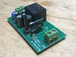
Today we are looking inside another WiFi-controlled transmitter compatible with the Tuya application, confusingly similar to the well-known Sonoff, available for purchase for about PLN 20. We will check on what system it is implemented and whether it can be uploaded with its own batch. Finally, I will also draw its full (hopefully) diagram. The topic will be interesting because the heart of this product will turn out to be the Realtek system, which most people associate with the subject of computing rather than IoT.
Purchase of a smart 10A On / Off relay
I found the product under the slogan "NEW Tuya Smart Switch 10A 2200W Wifi Basic Diy Switch Module App Control Support Off-line Operation Compatible Alexa Smart Life", although it is also known as NF101-A. Here is one of the offers to sell it:
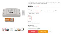
It is worth paying attention to the large selection of the country from which the shipment will be sent, Poland is also on the list. It is probably the result of the recent changes in the customs duty for shipments from abroad.
The product price is PLN 23 with free shipping, which is one of the cheapest WiFi-controlled transmitters I know.
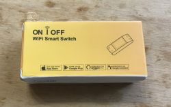
The characteristic yellow / orange box attracts attention.
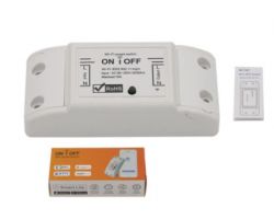
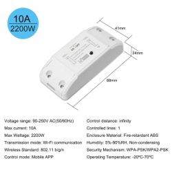
After receiving the parcel:
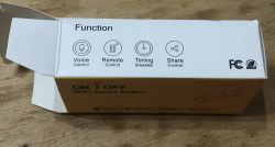
Instruction:


First connection:
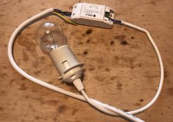
I also noticed that I think I got a newer version. Different shade of the box and the inscription "Tuya Smart Switch" instead of "Wi-Fi Smart Switch".
Related Topics
I have already written a few topics about WiFi products based on ESP (or similar systems). I mainly show interiors there.
I also describe the process of programming such a switch there and using it with the manufacturer's application (Blitzwolf, SmartLife, Tuya, eWeLink) or Tasmota.
I recommend that you familiarize yourself with these topics, I will not repeat all the information several times and as a rule, they apply to all products of this type.
List below:
- BW-LT30, i.e. a WiFi adapter for a light bulb - test, teardown and uploading ESP firmware
- WiFi-controlled electrical socket - BW-SHP8 - start-up and tests
- Test and interiorBW-SS3, a WiFi light switch from Blitzwolf
- PS-16-M socket / plug with WiFi and eWeLink / Coolkit application - test and teardown
- SmartLife switch - test, interior and WiFi light switch programming (similar switch, but without RF and description of programming it in Arduino via cables)
- SC3-01 SmartLife switch and uploading ESP firmware via WIFI (tuya-convert / OTA) (this time programming via WiFi, no need to open the housing, no soldering of cables)
- WiFi QTouch switch can only be plugged into the L cable - test, interior, diagram (an interesting switch, which is implemented on the thyristor, not on the relay, but also has ESP8285 inside)
- WiFi SmartLife single-color LED strip dimmer - test, interior, diagram (interesting LED strip driver on MOSFET and WB3S transistor)
- SmartSwitch Tuya WL-SW01_16 16A WiFi - test, interior (WB2S)
- WiFi door / window opening sensor - test, interior, integration with other devices Search in topic (sensor based on the XR809 / XR2 module)
- Proprietary open firmware for XR809 compatible with Tasmota HTTP / Home Assistant (a detailed description of how to create your own batch for the door sensor on the XR809)
Additionally, the topic about Tasmota and the DIY version of the WiFi transmitter:
- ESP8266 and Tasmota - step-by-step control of the WiFi relay
Additionally, I recommend the topic about Home Assistant (which can control a collection of such devices):
Home Assistant Tutorial - configuration, WiFi, MQTT, Zigbee, Tasmota
Pairing with the Tuya application
I've covered pairing in detail in previous topics in this series. Here, too, it went flawlessly, it was enough to put the device into the reset state (press the button for more than 5 seconds) and then via the Tuya application (after creating the account and confirming the email) select its type, enter information about our WiFi network and confirm the pairing.
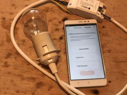
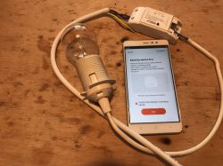
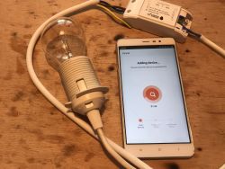
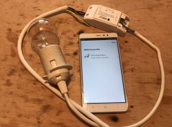
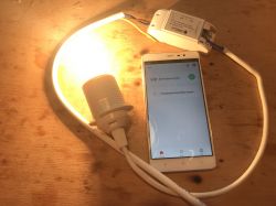
Everything in the application is standard, you can do scenarios, automations, etc.
Interior
You can get inside by simply levering the casing:
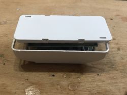
The housing is so matched to the board that you do not need screws:
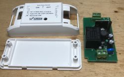
Plate:
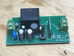
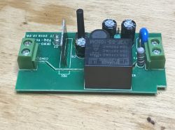

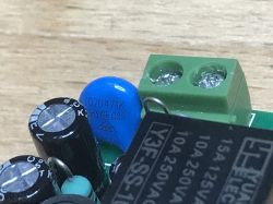
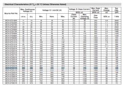
Varistor protecting the system against overvoltage (07D471K):
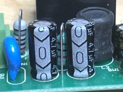
A filter with two 4.7uF 400V capacitors and a choke (pi type filter), in the background a fuse resistor:
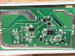
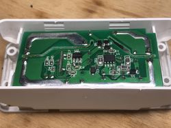
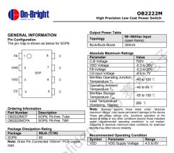
The bottom of the board, the whole system is transformerless powered by On-Bright OB2222MCP (OB2222) which gives about 5V at the output, for the 3.3V WiFi module it provides AMS1117 3.3:

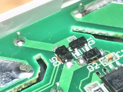
Transistor J6 switching the relay on and the necessary diode parallel to the relay coil (so-called freewheeling diode):
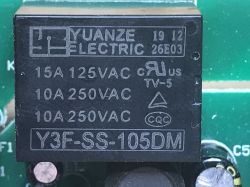
Relay itself, Yuanze Electronic, Y3F-SS-105DM:
And most importantly - the WiFi module (it was already with the cover removed, sometimes I meet with something like that, e.g. in the case of two XR809 door sensors that I had, one was without a screen and the other with):
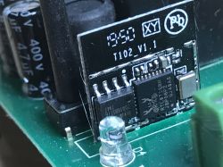
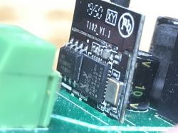
Unfortunately, ESP8266 is not here. There is a Realtek IC, RTL8710BN:
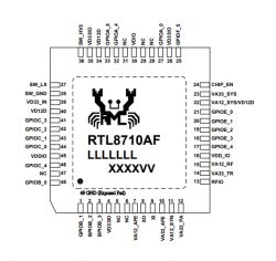
Quote:
RTL8710BN
AMEBA Z SERIES, IOT LOW-ENERGY SOC
The Realtek RTL8710BN is a highly integrated single chip with a low-power-consumption mechanism ideal for IoT (Internet of Things) applications. It combines an ARM(R)Cortex (TM) -M4 MCU, Wireless MAC / Baseband / RF, and configurable GPIOs that can function as digital peripherals for various product applications and control usage.
The RTL8710BN's embedded memory configuration enables simpler and faster application development.
CPU
- ARM(R)Cortex (TM) -M4 (up to 125MHz)
Memory
- 512KB embedded ROM
- 256KB embedded SRAM
- XIP (eXecut In Place)
- Provides external Flash interface
Wi-Fi
- 2.4GHz 1T1R 802.11b / g / n up to 150Mbps; 20MHz and 40MHz
Security
- Wi-Fi WEP, WPA, WPA2, WPS
- Security engine: MD5, SHA-1, SHA2-256, DES, 3DES, AES
Peripheral Interface
- SDIO Slave
- UART x 2
- SPI interface (Master / Slave)
- I2C interface x 2
- ADC for voltage management
- PWM x 5
- Maximum 17 GPIOs
Package
- Type: QFN-32
- Size: 5 x 5 mm
RTL8710BN comes with Flash on SPI (similar to ESP), let's take a closer look at how:
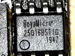
Boya Micro, 25Q16BSTIG as far as I can see, similar to 25Q16BVSIG (BY25Q16BS family).
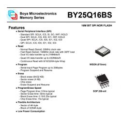
NOR Flash memory with SPI interface, 16M BIT or 2MB.
T102_V1.1 module (such a different WR2?) From inside
I desoldered the WiFi module from the inside to be able to read the pin names.
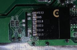
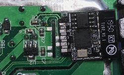
Leads are signed. there is also a catalog note on the network under the entry T102_V1.1:
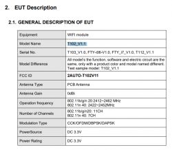
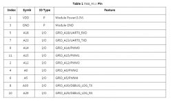
Its parameters:
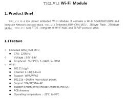
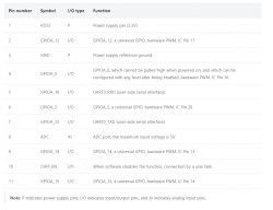
Pinouts and roles of pins:
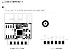
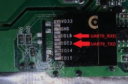
There are also UART pins:
In addition, I noticed that the Tuya, WR2 module (also implemented on RTL8710BN) is very similar to it:
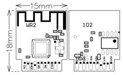
Pin 29 in the photo is EN in the schematic and 30 is ADC.
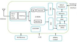
The information about the 40MHz resonator is also correct, the module from the topic has it visible on the board:
Pinout WR2:
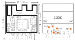
Additionally, the pinout is compatible with TYWE2S (which is already based on ESP):
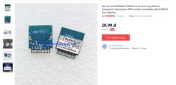
and TYWE3S can already be bought sometimes (and there are different prices, the one in the screenshot is not very attractive, actually it is more than the cost of the entire relay):
There are some of these modules, so much good that they match as they come out.
RTL8710BN programmable?
I already had the module desoldered, so I took the first steps towards possible programming.
From what I can see, TUYA_IOT_SDK probably supports it:
https://github.com/TuyaInc/TUYA_IOT_SDK
Without Tuya, IAR Embedded Workbench can be used:
https://www.amebaiot.com/en/ameba-sdk-getting-started-8710bn/
There are also other possibilities, e.g. via Arduino IDE:
https://github.com/Ameba8195/Arduino/
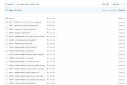
There is some documentation from Realtek:
https://github.com/jialexd/sdk-ameba-v4.0c_180328/tree/master/doc
Long topic on esp8266.ru:
https://esp8266.ru/forum/threads/arduino-dlja-rtl8710.1787/
As for the method of uploading the batch, I am afraid that it will not do without a normal programmer (J-Link? J-Trace, probably?), Because I did not find the documentation for a possible RTL bootloader:
https://www.programmersought.com/article/2943525450/
In RTLDuino there is supposedly some way to OTA (firmware update via WiFi), but it still requires a single bootloader (ota_non_block.ino or ota_block.ino).
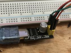
I started the module on the contact plate. It does not require anything other than a power connection to start up:
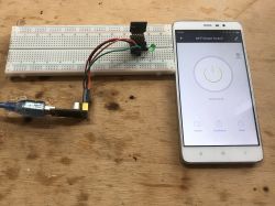
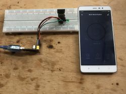
In this configuration, the Tuya mobile application continues to work and allows you to control the module. I connected the LED to the pin that previously controlled the relay and the control also works.
I also checked the UART ports of the module:
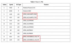
Nothing is happening on the normal RX / TX pins. In contrast, the UART debug output sends some information with baud = 115200.
ROM:[V0.1]
FLASHRATE:4
BOOT TYPE:0 XTAL:40000000
IMG1 DATA[1168:10002000]
IMG1 ENTRY[8000541:100021ef]
IMG1 ENTER
CHIPID[000000ff]
read_mode idx:3, flash_speed idx:0
calibration_result:[1:5:11][9:d]
calibration_result:[2:13:7][1:d]
calibration_result:[3:7:5][1:7]
calibration_ok:[2:13:7]
FLASH CALIB[NEW OK]
OTA2 ADDR[80d0000]
OTAx SELE[fffffffc]
OTA1 USE
IMG2 DATA[0x809a7e0:6660:0x10005000]
IMG2 SIGN[RTKWin(10005008)]
IMG2 ENTRY[0x10005000:0x800b1a5]
===== Enter Image 2 ====
System_Init1
OSC8M: 8386568
boot reason: 0
System_Init2
11111111111111111111111111
interface 0 is initialized
interfa[01-01 ce 1 is ini18:12:15 TUYtialized
A Debug][tu
Initializiya_device.c:ng WIFI ...517] < TUYA
LDO IOT SDK V:2.Mode, BD_In0.0 BS:30.04fo: 0
_PT:2.2_LAN:3.3_CAD:1.0.2_CD:1.0.0 >
LDO M
< tuya_ioode, BD_Inft_lib BUILD o: 0
AT:2019_06_21_14_56_08 BY tuya_iot_team AT 8710_2M >
IOT DEFS < WIFI_GW:1 DEBUG:1 KV_FILE:0 SHUTDOWN_MODE:0 LITTLE_END:1 TLS_MODE:3 ENABLE_LOCAL_LINKAGE:0 ENABLE_CLOUD_OPERATION:0 ENABLE_SUBDEVICE:0 ENABLE_ENGINEER_TO_NORMAL:0 OPERATING_SYSTEM:2 ENABLE_SYS_RPC:0 TY_SECURITY_CHIP:0 RELIABLE_TRANSFER:RELIABLE_TRANSFER ENABLE_LAN_ENCRYPTION:1 ENABLE_SIGMESH:0 >
[01-01 18:12:15 TUYA Debug][tuya_device.c:518] oem_rtlbn_fty_on_off_2M:1.0.3
[01-01 18:12:15 TUYA Notice][simple_flash.c:428] key_addr: 0x1eb000   block_sz 4096
[01-01 18:12:15 TUYA Notice][simple_flash.c:496] get key:
0x4a 0xf4 0xce 0x1c 0xeb 0xec 0x8 0xb0 0xfd 0x88 0xed 0x59 0xcc 0x43 0xed 0xfd
WIFI initialized
init_thread(55), Available heap 0x9ea0[01-01 18:12:15 TUYA Notice][tuya_uart.c:125] 1   9600
[01-01 18:12:15 TUYA Notice][tuya_main.c:368] mf_init succ
[01-01 18:12:15 TUYA Notice][tuya_device.c:219] rst_cnt:1
[01-01 18:12:15 TUYA Notice][gw_intf.c:2600] serial_no:68572da1e013
[01-01 18:12:15 TUYA Notice][gw_intf.c:2631] gw_cntl.gw_wsm.stat:2
[01-01 18:12:15 TUYA Notice][gw_intf.c:2634] gw_cntl.gw_wsm.nc_tp:3
[01-01 18:12:15 TUYA Notice][gw_intf.c:2635] gw_cntl.gw_wsm.md:0
[01-01 18:12:15 TUYA Notice][gw_intf.c:2667] gw_cntl.gw_if.abi:0 input:0
[01-01 18:12:15 TUYA Notice][gw_intf.c:2668] gw_cntl.gw_if.product_key:key8k3dvn7qq4g5x, input:key8k3dvn7qq4g5x
[01-01 18:12:15 TUYA Notice][gw_intf.c:2669] gw_cntl.gw_if.tp:0, input:0
[01-01 18:12:15 TUYA Notice][gw_intf.c:2671] gw_cntl.gw_if.firmware_key:key8k3dvn7qq4g5x, input:key8k3dvn7qq4g5x
[01-01 18:12:15 TUYA Notice][tuya_gpio.c:225] id 5 {0x10018164}
[01-01 18:12:15 TUYA Notice][tuya_device.c:583] cd_timer ID:21
LwIP_DHCP: dhcp stop.Deinitializing WIFI ...WIFI deinitializedInitializing WIFI ...
LDO Mode, BD_Info: 0
LDO Mode, BD_Info: 0
WIFI initialized
[01-01 18:12:16 TUYA Notice][wifi_hwl.c:759] ssid: MY_WIFI_SSID,passwd:MY_WIFI_PASSWORD_IN_PLAINTEXT,sec_type: 4194308,chan:3
RTL8195A[Driver]: set ssid [MY_WIFI_SSID]
RTL8195A[Driver]: start auth to 30:b5:c2:5d:70:72
[01-01 18:12:17 TUYARTL81 Notice][hw95A[Driver]:_table.c:38 auth succes5] wifi stas, start asstus is :5
oc
RTL8195A[Driver]: association success(res=7)wlan1: 1 DL RSVD page success! DLBcnCount:01, poll:00000001
RTL8195A[Driver]: set pairwise key to hw: alg:4(WEP40-1 WEP104-5 TKIP-2 AES-4)
RTL8195A[Driver]: set group key to hw: alg:4(WEP40-1 WEP104-5 TKIP-2 AES-4) keyid:
[01-01 18:12:18 TUYA Notice][hw_table.c:385] wifi status is :6
[01-01 18:12:18 TUYA Err][smart_frame.c:2060] mqtt async send fail -916
[01-01 18:12:18 TUYA Err][tuya_iot_com_api.c:676] dp report async fail.ret:-916
[01-01 18:12:18 TUYA Err][tuya_device.c:395] upload_all_dp_stat op_ret:-916
Interface 0 IP address : 192.168.0.106[01-01 01:00:03 TUYA Notice][mqtt_client.c:1075] mqtt get serve ip success
[01-01 01:00:03 TUYA Notice][mqtt_client.c:1100] mqtt socket create success. begin to connect
[01-01 01:00:03 TUYA Notice][mqtt_client.c:1115] mqtt socket connect success. begin to subscribe
[01-01 01:00:03 TUYA Notice][mqtt_client.c:878] mqtt subscribe success
[01-01 01:00:04 TUYA Notice][hw_table.c:385] wifi status is :7
[01-01 01:00:04 TUYA Notice][wifi_hwl.c:747] ssid MY_WIFI_SSID,passwd:MY_WIFI_PASSWORD_IN_PLAINTEXT,sec_type:4194308,chan:3
[01-01 01:00:04 TUYA Notice][gw_intf.c:761] get ap info: ssid:MY_WIFI_SSID,passwd:MY_WIFI_PASSWORD_IN_PLAINTEXT,chan:3,sec_tp:400004
[01-01 01:00:04 TUYA Notice][gw_intf.c:762] local ap info: ssid:MY_WIFI_SSID,passwd:MY_WIFI_PASSWORD_IN_PLAINTEXT,chan:3,sec_tp:400004
The log obviously contained information about my WiFi (along with password) which I censored above. There is also a Tuya Device Key that can come in handy for Local Tuya in Home Assistant (to be described soon).
The filenames point to this SDK, which is quite obvious, Tuya produces all these modules:
https://tuyainc.github.io/TUYA_IOT_SDK_doc/zh-hans/resource/SDK_directory.html
Code:
https://github.com/TuyaInc/TUYA_IOT_SDK
Diagram
Based on the photos and catalog notes of the elements, I have prepared a full diagram of this relay.
NOTE: The scheme uses markings such as on the board, in addition, the resistor values are in the SMD code (e.g. 152 means 1.5 k?
In a nutshell: we have a few simple protections (at least there is a fuse, etc.), then a transformerless power supply (buck) on OB2222 giving 5V, a 5V relay controlled by a transistor and a 3.3V LDO powering the WiFi module, button, diode and that's it.

You can see some differences from the scheme proposed in the catalog note OB2222. The manufacturer of the relay resigned from the rectifier bridge in favor of one diode, but added an additional filter (two electrolytic capacitors and a choke forming the PI filter).
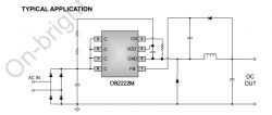
The rest is in line with the note (R1 and R2 are the power supply for OB2222, together with the C2 electrolytic capacitor), RS1 (S in the name is from Current Sense) is a low resistance resistor, a shunt to control the inverter current, further downstream elements D3 and L2s are already characteristic of every buck converter.
General diagram of a buck converter:
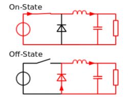
(source: wikipedia, https://en.wikipedia.org/wiki/Buck_converter)
OB2222 obviously has the transistor integrated with the rest of the controller in its housing.
This additional D2 diode connected to the FB (Feedback) pin is a feedback for current control via OB2222.
OB2222 provides 5V which is used to turn on the relay and supplies the 3.3V LDO stabilizer AMS1117.
Only this 3.3V supplies the T102_V1.1 module with RTL8710.
Pin IO14 is connected to the transistor with the J6 code (I suspect it is S9014) through the R6 resistor limiting the base current and the R7 resistor acting as a pull down.
The IO0 pin is just for the LED (informs about the relay status and the pairing status).
Pin IO5 is a button with a pull up resistor R5 and surprisingly with a capacitor C8 which probably reduces the problem of contact vibration.
Summary
The product is quite cheap, but from what I can see it does not match the price of the classic Sonoff (I can see it even for PLN 20) and there are basically no reasons to choose it specifically.
The module used inside does not rely on ESP and seems to be quite difficult to program and basically offers us nothing more than ESP.
Theoretically, the module inside could be replaced with another one, but it is completely unprofitable.
So by buying it, we won't play much, we won't play Tasmota, etc. It's better to buy Sonoff.
Of course, this does not mean that this purchase was in vain - as for me, on the contrary - I am going to be interested in the current RTL8710 / T102_V1.1 soon and still try to program it / compile a batch for it, and if something comes out of it, the results will be I will also describe it on the forum.
You can always learn something interesting from such modules, I, for example, did not expect that such a module would barely print the SSID and password of my WiFi network on UART ... in the garbage, connects and already has access to our WiFi.
For those interested: I am enclosing materials related to the relay from the topic.
Cool? Ranking DIY Helpful post? Buy me a coffee.


