Temperature "stabilizer" for transformer soldering iron.
For many years I have been irritated by the lack of control over the temperature of the transformer soldering iron tip.
I tested various circuits, regulation on thyristor, impulse control of the soldering iron by a multivibrator - don't build it, it's a waste of time.
These systems do not fulfill their function, especially with a triac, it is NOT a good idea to combine the inductance of the transformer and the system that generates chaff from the sine wave. Seemingly it works, but the transformer works in very unfavorable conditions.
The word "stabilizer" is quite exaggerated because the system does not stabilize anything but "cleverly" reduces the temperature of the soldering tip.
ATTENTION - I do not recommend the design for inexperienced people - there is a risk of electric shock, the whole system is under 230V mains voltage.
Take special care when performing the layout and testing. Probably all users of a transformer soldering iron noticed that soldering with such a soldering iron requires a lot of practice in order not to cause losses with too high temperature.
The problem is the lack of control over the tip temperature, closely related to the time the soldering iron is turned on.
I decided to fix it a little bit. The first step was to check how the transformer soldering iron behaves when the supply voltage is lowered.
For testing, I used a soldering iron originally adapted to 220V - this is the only one I have.
The tests were performed using an autotransformer with smooth voltage regulation from 0 to 250V.
By lowering the voltage in increments of 10 V, I checked whether it could be soldered, I reached a voltage of 170V at which my soldering iron practically stopped melting tin.
At 200V, I did not notice any problems with soldering, but I noticed that even longer heating of the soldered place does not degrade the PCB as with 230V.
The conclusion is obvious - lower the voltage supplied to 200V, a good solution would be the automatically decreasing linearly lowering voltage of the soldering iron in about 1 second from 230 V to 195-200 V. Why so - to quickly warm up the tip and then just keep it its temperature.
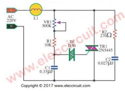
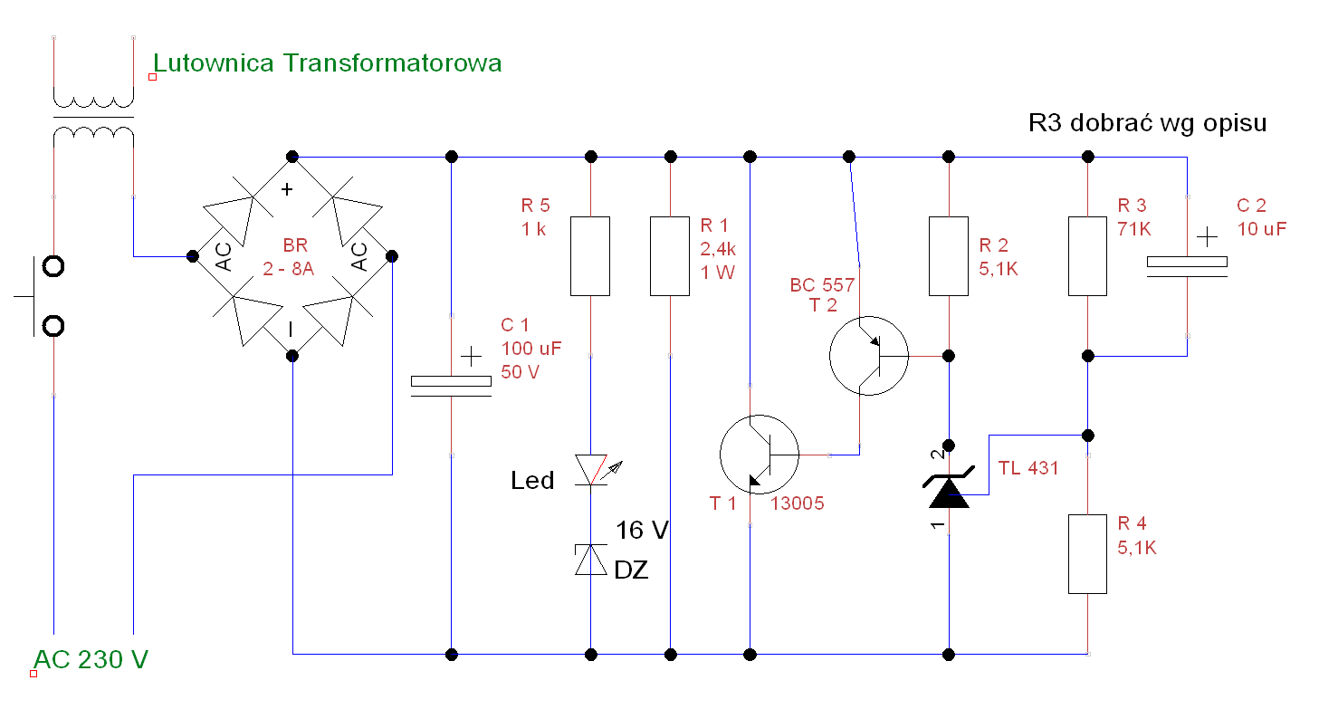
I came up with the idea to use a programmable zener diode for this purpose, i.e. a very popular TL431 integrated circuit.
The circuit works as a power zener diode according to the manufacturer's application, but how to increase the voltage linearly to 0 to 30V?
Therefore, I made small changes to the typical scheme in order to obtain the effect of a linear voltage ramp.
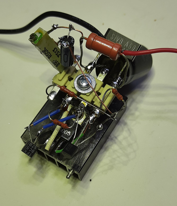
The test version looked like this.

The system is connected in series with the soldering iron in the primary circuit of the transformer and it reduces the voltage supplied linearly by about 33V (this voltage must be selected for your soldering iron).
The divider setting the stabilization voltage is selected for a voltage of about 31V (the R3 resistor turned out to be 71 K for me), it suggests trying to start with a lower value. The 31V voltage is almost the maximum operating voltage of this system.
Higher voltage can be dangerous for the TL431 chip - different manufacturers list 30 to 37 V max.
How the circuit works - please pay attention to C2 - the speed of voltage rise depends on it.
The voltage rectified by the rectifier bridge charges the capacitor C1, which gives almost a short circuit in the first fraction of a second (voltage loss only on the diodes).
The voltage begins to build up on C1, which causes the capacitor C2 to be charged simultaneously, the charging current C2 causes almost full voltage at input TL431 equal to the voltage at C1. The TL 431 circuit drives the transistors which limit the voltage on C1, but the capacitor C2 continues to charge and after a while it becomes charged, the circuit reaches equilibrium and the voltage set by the divider R3 / R4. As I wrote above, it is about 31 V. The power transistor must be screwed to a small heat sink, about 12-15 W is lost on it. The fact that only during the operation of the soldering iron a few seconds but seconds to seconds and it gets warm.
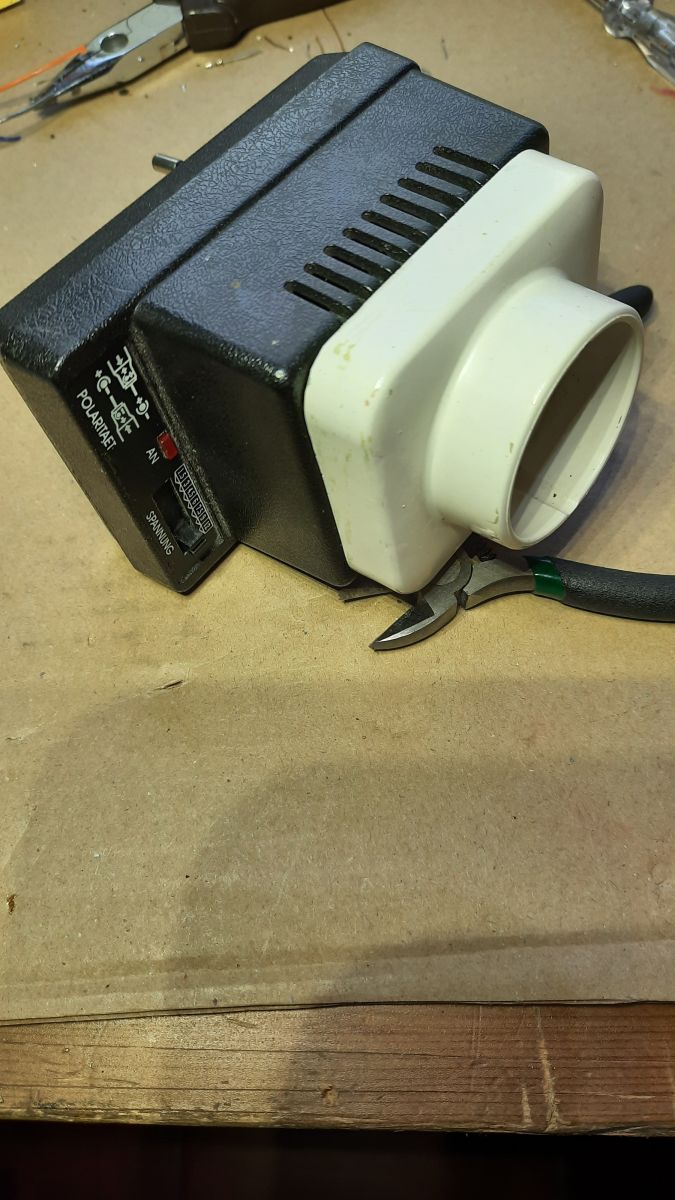
The diagram also shows a diagnostic detail whether the system is working, it is a 16V zener diode connected in series, a LED and a current limiting resistor. The LED diode turns on when the voltage reaches about 20V, which indicates that the system is working.
During construction and testing, it can be done safely, it is enough to use a power supply with a voltage regulation of 20-40 V and, for example, a 12 V / 5W car bulb connected in series. this will allow the voltage to be established safely.
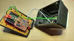
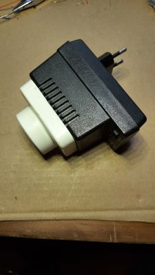
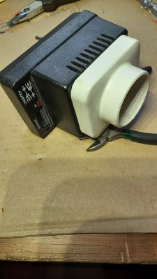
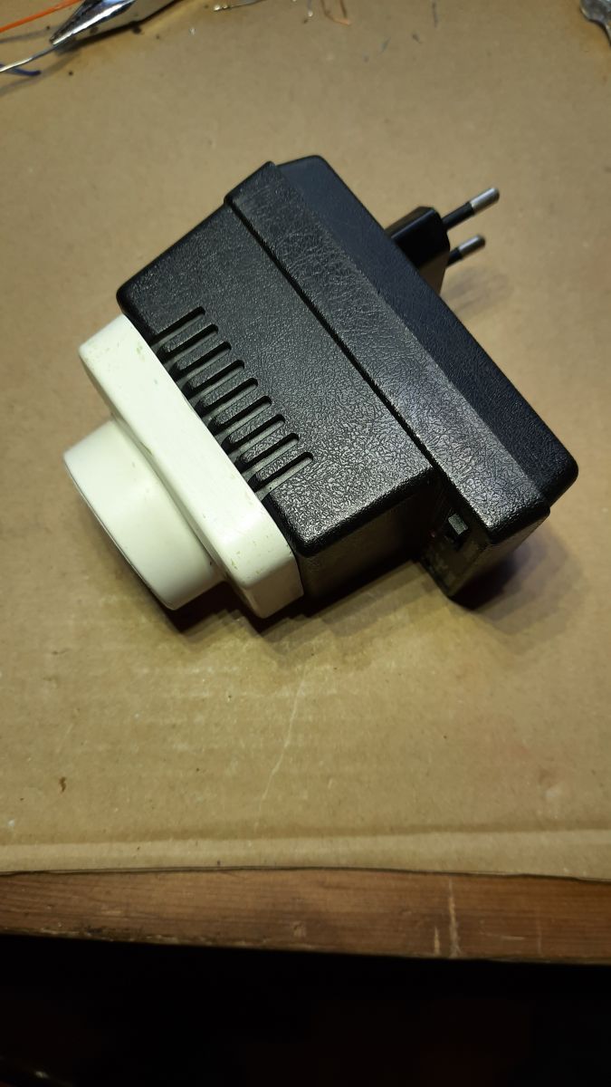
The whole thing was built in an old housing after a plug-in power supply with an added socket. Therefore, it is an independent module to which soldering irons can be attached as needed.


Comments
Simple and useful. I will add that the R1 resistor shortens the time to return to the starting position. [Read more]
Heh, good xD. All the more so: if 30V is so important to you, it can be especially useful when you have a solar farm (or in the vicinity), although then it would be useful to sometimes reduce 50V. From... [Read more]
I do not see the temperature sensor - it is rather a POWER LIMITER for a TRANSFORMER SOLDERING IRON. I admire the amount of effort in relation to the result .. You could also give 2 24V bulbs properly... [Read more]
Hello. I solder a lot with a transformer tube myself, and to be honest, I am more pissed off by the changing parameters of the tip itself along with its gradual wear, than the problem with the supply... [Read more]
Is this something for me? Nobody said that at the beginning it would go to tl431, but you have to start somewhere with some basic prototype ... Of course, the temperature control of the tip is out of the... [Read more]
Everything is fine, I am glad that the system works, but I am bothered by one question (my colleague above also partially noticed this) - what will happen when you replace the tip and its parameters change?... [Read more]
That's right, I was curious if anyone would notice what he was for - congratulations. [Read more]
Beginners should pay attention to one more aspect of the construction of this system - it should be very carefully checked before the first start-up, not only visually, but also with an ohmmeter. Lack... [Read more]
That's why I took the easy way and I have the soldering iron connected to the autotransformer set to 200V. An accelerated start is not needed, you just wait a few seconds longer for the tip to warm... [Read more]
You exaggerate ... It is enough to put a suitable zener diode in parallel to E and C of transistor T2, or some resistance divider on the base of T1 and it is much safer ... :D [Read more]
Since you correct the layout and write that it will be much safer, it means that I am not exaggerating :) I do not write that the circuit is bad - just if T1 does not limit the voltage, there will be... [Read more]
What I meant was that the author provided relevant information about this fact; And I suggested a minor correction prophylactically for greater safety ... :D [Read more]
The same can be achieved by using an ordinary 230V / 24V mains transformer. When working in such short pulses, it can even be a small, temporarily overloaded transformer. Network transformers, when connected... [Read more]
I already thought that the TL431 you control the thermistor located on ... well, you can't attach anything to the tip here :) I also used to think about stabilizing the tip temperature in a transformer... [Read more]
Very interesting layout and at one point I was thinking about duplicating it for my soldering iron. However, I will still stick to the old structure. [Read more]
Thanks for the idea! It is a bit tiring that someone "knows better what is good" and recommends "buy a station, what do you need a transformer". Or maybe who just has a station (for 30 years, there was... [Read more]
I use the ST50 pace station every day, I solder quite a lot on it (maybe not every day, but still) and although as it is a pace, it heats up in several seconds, I often use a transformer and nothing can... [Read more]
Everything can be measured on the primary. (voltage, current) ... You only need to calibrate the system at the beginning to the no-load losses trafo + there are some pennies for the bulb itself. An algorithm... [Read more]
[Read more]