logo elektroda
logo elektroda
X
logo elektroda

How to build a rechargeable transformer soldering iron with TL494?

Sentox 5244 29
ADVERTISEMENT
Treść została przetłumaczona polish » english Zobacz oryginalną wersję tematu
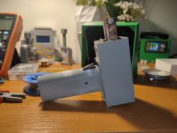
  • Prototype of a battery-powered soldering iron on a table
    Hello.
    I used to really like the rechargeable soldering iron from this post: https://www.elektroda.pl/rtvforum/topic3303762.html and recently stated that I would attempt my own build. I already had all the parts recycled, the only thing missing was a flat bar for the secondary winding but this was found. The first prototype was according to the diagram from the link, but it didn't work very well, the zener diode (in my case a B-E transistor) got very hot and there was a lot of power loss. Well, but since I had a tl494 from an old ATX I figured I'd do it again only push-pull this time. It worked much better, the heatsink from the transistors is cold, the power is not missing.
    The operating frequency is 4Khz. The transformer is from an atx power supply and is probably ~1.2cm2 in cross section. The transformer generates its own power for the controller, the push-pull topology doubles the voltage on the primary side so it works great for us if the supply voltage is low. We have about 9-12V on the controller. The whole circuit requires at least 7V to start, below this something works, but the keys do not open fully and it is not able to generate a higher voltage to start. The trip threshold can be lowered by replacing silicon diodes with schottky diodes and/or transistors with a lower opening voltage. In theory the tl494 has undervoltage protection but something this piece of mine works even at <6V just produces some impaired waveform. But once it fires it works and even goes below 6V. There is a hole on the back of the case to adjust the power by changing the PWM fill. The blade is 0.75mm wire. The flat bar is 15x3mm, 12cm long. Because of the size and the material, the loss from conduction is negligibly small, but the loss from heat removal from the mainsail is already quite considerable and it heats up with continuous operation. If I were to make a second one, I would rather aim for an aluminium flat bar, I would make it longer and it would be even lighter and wouldn't pick up heat from the mainsail as much.
    I made the winding from the kind of wire I had, the primary atx I think, a bit too thin but that's hard, it works. I measured twice 15 turns and at the output I have ~0.5V and all in all this is still too much, the mains only has 0.25V. And as you know twice the voltage requires 4 times less resistance to get the same power. So the blade needs to be quite thin, the one I have now is still a bit too thick and I need to have the power twisted. But too thin a blade will be too soft so it's not so easy to adjust. The problem with a heavy load(read thick/short arrowhead) is big voltage spikes on the transistors, up to 70V. For higher power you would need to improve the snubber network , you can add zeners to the transistors.
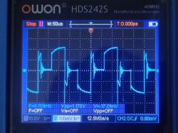
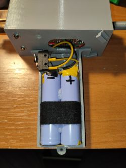
    The current on the secondary is between 50 and 80A. The power supply is cells from a stripped Bosch hoover battery, they still have 1.8ah and a resistance of 35mR. The final weight is 300g. I still plan to add a power switch and a module to charge the battery when the stuff arrives from china. In the picture with the oscilloscope is the waveform on the flat iron at partial power. In the video he is testing the soldering iron at full power on a small heatsink.
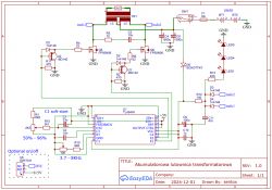
    Circuit diagram of a battery-powered transformer soldering iron. .
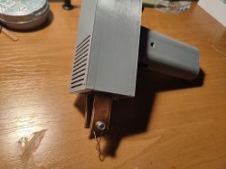
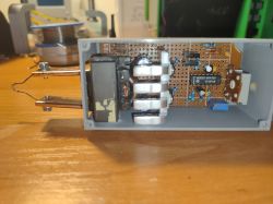
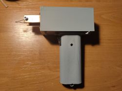
    Prototype battery-powered soldering iron on a desk DIY battery-powered soldering iron on a workbench. Oscilloscope screen displaying a waveform with a frequency of about 8.113 kHz. Interior of soldering iron housing with visible two battery cells. View of the interior of a DIY battery-powered soldering iron with electronics and a tip. View of the interior of a DIY battery-powered soldering iron with electronics and a tip. .


    .

    Cool? Ranking DIY
    About Author
    Sentox
    Level 12  
    Offline 
    Sentox wrote 46 posts with rating 36, helped 5 times. Been with us since 2012 year.
  • ADVERTISEMENT
  • #2 21341909
    zgierzman
    Level 31  
    I for one would probably end up in a psychiatric locked ward very quickly if I were to use your invention.
    I couldn't even manage to watch this short film without turning off the sound - the beeping immediately causes me pain somewhere behind my eyes.
  • #3 21341939
    Karol966
    Level 31  
    Cool, I like the idea as well as the execution. Would it be worth to use here additionally some small uP to e.g. limit PWM filling automatically after heating the mainsail?
  • #4 21342724
    acctr
    Level 38  
    How does the soldering iron perform with the thicker wire as a tip?
    zgierzman wrote:
    I couldn't even manage to watch this short video without turning off the sound - the screeching immediately causes me pain somewhere behind my eyes.
    .
    Do you hear any squeaks?
    Helpful post? Buy me a coffee.
  • #5 21343047
    Sentox
    Level 12  
    The circuit squeaks in 4 kHz, you can definitely hear it, you would have to glue the transformer or something, but it doesn't bother me so far. To control the temperature of the mainsail, I don't even need a proxy, because the controller has operational amplifiers, but I need to measure the temperature of the mainsail somehow, but with what? Of copper thicker can not be, too high currents on the secondary, too large voltage pins. Too bad I don't have aluminium wires of any kind. But now I have a mainsail from two paper clips, steel, and even that works. About ~3 A it draws on this mainsheet. For the steel wires you would have to reduce the gearing to make it higher voltage.
  • #6 21343636
    Andrzej_Tomaszewski
    Level 13  
    Welcome,

    What is the purpose of this design? How is it better than a traditional transformer soldering iron? Indeed this squeak is hard to listen to.

    Regards
  • ADVERTISEMENT
  • #7 21343677
    slaw0
    Level 15  
    Andrzej_Tomaszewski wrote:
    Hello,

    What is the purpose of this design? How is it better than a traditional transformer soldering iron? Indeed this squeak is hard to listen to.

    Greetings
    .
    Such a design can be appreciated once you have used it a bit. I also once made something similar https://www.elektroda.pl/rtvforum/topic3785596.html and it is still in use. It is indispensable for small repairs, such as soldering one or two components or a wire, without the need to unwind cables and look for a socket. Recently I used it in my car to solder a wire and it worked fine. I congratulate the author on the construction and suggest pouring glue over the trafo. Mine is almost silent after this procedure.
  • ADVERTISEMENT
  • #8 21343784
    żarówka rtęciowa
    Level 37  
    Hello

    Sentox wrote:
    Copper thicker can't be, too much current on secondary, too much voltage pins. Pity I don't have aluminium wires of any kind. But now I have a spearhead made of two paper clips, steel, and even that works. About ~3 A it draws on this mainsheet. For steel wires, you would have to reduce the gearing to make it higher voltage.


    Steel has several times the resistance compared to copper. The advantage is that iron does not dissolve in tin, so the blade will have a long life. With a precision current source of 5-20 A and a suitable millivoltmeter, the resistance of the arrowhead can be measured using the technical method.
  • #10 21344153
    CosteC
    Level 39  
    How did you measure the current on the secondary side?
    And how much power does it have realistically?
    I'm a bit confused why 4 kHz and not 25-30 kHz, so that at least it doesn't squeal so cruelly.
  • #11 21344177
    krakarak
    Level 42  
    Idea good, execution so-so. Definitely needs fine-tuning and getting rid of the squeak.
  • #12 21344216
    Sentox
    Level 12  
    >>21344153 .
    On the secondary side, the current is measured by measuring on the primary side and multiplying by 15. A 4KHz because to reduce the skin effect on the flat.
  • #13 21344253
    CosteC
    Level 39  
    At 4 kHz the penetration is at 1 mm... for 20 kHz 0.46 mm
    Like replacing the flat bar with sheet metal it would work better and wind up easier....

    The secondary current is not 15 times the primary current - this trafo has poor magnetic coupling - there is only one, and poorly wound, coil.
  • #14 21344265
    sortes
    Level 13  
    Eastern DIYers also had ideas for an electronically controlled induction soldering iron.
    This is one such article:

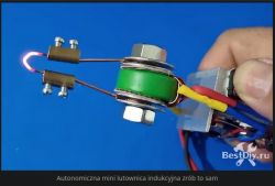
    Autonomous DIY mini induction soldering iron. .

    An induction soldering iron is a pretty good tool in terms of performance, it heats up instantly, which is why it's called an "instant-heat pulse soldering iron", it has a lot of power and can heat up pretty massive components and pads on PCBs, but it does have drawbacks, they are that it needs 220V mains power and it's large in size.
    But you shouldn't fret because you can still make your own compact and simple induction soldering iron, you can power it with a battery and take it with you to places where there's no socket nearby, and it's also quite compact.


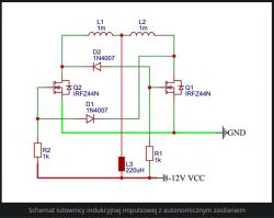
    Circuit diagram of an autonomous power supply impulse induction soldering iron. .

    Autonomous mini induction soldering iron with a glowing tip. .

    Parts and materials:
    IRFZ44N transistor - 2 pcs;
    1N4007 diode - 2 pcs;
    1 kOhm resistor - 2 pcs;
    Li-Ion 18650 3.7 V battery - 2 pcs;
    Induction coil 220 µH;
    0.8 mm varnish-insulated copper wire;
    Ferrite ring;
    18650 battery holder.


    Here an example using an electronic transformer used to power 12-volt halogen lamps as a soldering iron:
    Simple pulse soldering iron based on an electronic transformer.
    Direct DIY pulse soldering iron.
  • #15 21344569
    slaw0
    Level 15  
    CosteC wrote:
    How did you measure the current on the secondary side?
    And how much power does it have realistically?
    I somewhat don't understand why 4 kHz and not 25-30 kHz, so that at least it doesn't squeal so cruelly.
    .
    At 25 kHz you have to reduce the number of turns on the primary, and on the secondary you can no longer do that and the voltage will be too high.
  • #16 21344606
    gulson
    System Administrator
    Thanks for sharing the build, as I understand it is a soldering iron for field work? :) .
    Send me a Parcel Post on Private Message and I will send a small gift.
  • #17 21345504
    LEDówki
    Level 43  
    You take your time to mute the inverter. Rodents leave areas where sounds above 3 kHz are propagated. You have a mouse deterrent right away. You run it in autumn and there will be fewer rodents in the area.
  • #18 21345535
    sortes
    Level 13  
    >>21345504 .

    I continue with your joke:

    Too simple to complicate!
    The dream of many.
    How to repair with such a soldering iron in the field?
    Something sparks, sometimes squeaks....
    Some solder not making contact?
    He wanted to solder,
    and the electronics in it failed.
    He sat down and thought for a while,
    What's a head for?
    - A soldering iron in the field?
    - Only a resistance one!
  • #19 21346109
    popek9
    Level 13  
    On aliexpress you can buy very good soldering irons for T12 arrowheads with usb-c socket for up to £ 100. Add to this a powerbank with PD 3.0 support for 20 volts and you have a ready mobile kit. It only takes a few seconds to heat up the soldering iron to the set temperature. Making a rechargeable transformer soldering iron is pointless. It is big not handy and has a big downside - a hopeless tip.
    A plus for the willingness and the work put in, but that's the end of the positives.
  • #20 21346349
    maliniak80
    Level 17  
    popek9 wrote:
    On aliexpress up to 100 zł you can buy very good soldering irons for T12 arrowheads with usb-c socket. Add to this a powerbank with PD 3.0 support for 20 volts and you have a ready mobile kit. It only takes a few seconds to heat up the soldering iron to the set temperature. Making a rechargeable transformer soldering iron is pointless. It is big not handy and has a big downside - a hopeless tip.
    Plus for the willingness and the work put in, but that's the end of the positives.

    This is your opinion. I have been using the soldering iron as in the topic for years on some occasions and it sometimes beats the T12 (I have that three) so don't sow ferment. Soldering is not an end in itself. Congratulations on your project!
  • #21 21346372
    E8600
    Level 41  
    And I would say yes raise the frequency and miniaturise it to current standards and come up with some kind of tool-less arrowhead assembly.
  • #22 21346484
    jarek_lnx
    Level 43  
    Sentox wrote:
    To control the temperature of the mainsail it is even unnecessary to use a processor, because the controller has operational amplifiers, but you have to measure the temperature of the mainsail somehow, but with what?
    .
    For the mainsail, just weld or braze a wire of another metal and use it as a thermocouple. I used to have an idea for such a transformer soldering iron with stabilisation, maybe one day I will realise it.

    slaw0 wrote:
    At 25 kHz you have to reduce the number of turns on the primary, and on the secondary you can't do it anymore and the voltage will be too high.
    You may or may not need it.


    @Sentox haven't you considered the Mazzielli circuit? the waveform is sinusoidal it's less harmonics both audible and those that the radio will pick up.
  • #23 21346561
    slaw0
    Level 15  
    jarek_lnx wrote:
    .

    slaw0 wrote:
    At 25 kHz you have to reduce the number of turns on the primary, and on the secondary you can no longer do this and the voltage will be too high.
    You may or may not need to do this.
    .
    In what way? From my observations, raising the frequency with the same number of turns results in a drop in power, and to get a large current at the output the transformer must have the right gear ratio.
  • #24 21346585
    jarek_lnx
    Level 43  
    slaw0 wrote:
    From my observations, raising the frequency for the same number of turns results in a drop in power,
    .
    This is the case and it is due to the dissipation inductance, which we can influence. Besides, by gearing we can correct the voltage drop across the reactance of the dissipation inductance. The apparent power will increase, but this is not a tragedy. Unlike power supplies for electronics, here the output impedance does not have to be low, even better if it is higher, then the way the mainsail is made will have less impact on the power dissipated in it.
  • #25 21347031
    slaw0
    Level 15  
    Well, yes, except that with higher impedance more power goes into heating the tray and transistors. The subject is in spite of appearances difficult, maybe that is why there are no commercial impulse transformers. As for the earlier suggestions of soldering irons with t12 tips, I am absolutely not against these solutions and appreciate them too. If there were such soldering irons with a thermoprinter for 3.6V and about 20W then you could build something very nice and mobile powered from a single cell and charged from usb.
  • #26 21347033
    LEDówki
    Level 43  
    Powered by a single secondary or primary cell?
  • #27 21347078
    jarek_lnx
    Level 43  
    slaw0 wrote:
    The subject is counter-intuitively difficult, maybe that is why there are no commercial pulse transformers.
    Technically it is not that difficult. There are induction chargers where it is more difficult, and they are commonly manufactured. There are soldering irons with induction heating. There are no commercial pulse transformers because nobody wants to produce transformers at all.
    Do any of the top soldering iron companies have transformers? No, because it is equipment for the amateur and producing good transformers is a poor business idea.

    Transformers have some advantages, so I'm thinking of making one for myself. But in my own way

    Added after 4 [minutes]:

    Sentox wrote:
    In the video he is testing the soldering iron at full power on a small heatsink.
    Do you know any estimate of this power? How much does it draw from the power supply?
  • ADVERTISEMENT
  • #28 21349661
    Sentox
    Level 12  
    jarek_lnx wrote:
    @Sentox haven't you considered the Mazzielli circuit? the waveform is sinusoidal it's less harmonics both audible and those that the radio will pick up.
    .
    A bit off topic when it comes to such designs, I like this design of mine because you can control the fill. But a self-excited design like this would work well too.

    jarek_lnx wrote:
    Do you know any estimate of this power? How much it draws from the power supply?
    .
    At the time it was probably something around 5A going.

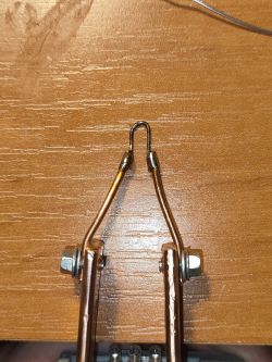
    I made such a tip out of copper wire and a steel paper clip, works pretty well, heats up instantly. You can even solder at 1A. At full power it draws 1.5-1.8A during operation. Surprisingly I soldered with lead tin and it doesn't come off during operation.
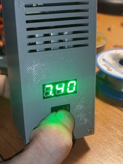
    I also added a voltmeter/ammeter. I made a 1A/1V transformer out of the lm358, you use the tie bar to select the voltage.

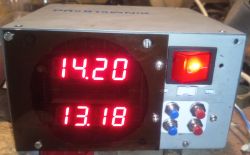
    DIY soldering iron made from copper wire and a paperclip. Close-up of a device housing with a display showing the value 3.48. .
  • #29 21349753
    bambus94
    Level 34  
    Maybe I'll get on with mine eventually too.
    After @slaw0's topic was published (3 years ago) I bought a broken makita screwdriver to put the guts in.
    And why is that? Because I have a lot of makita gear and batteries so I wouldn't have a problem with power. And also the handle is ergonomic right away, with a button.
    And as for the skin effect, what's the problem of winding the primary winding with a face and the secondary with tape?
  • #30 21349788
    Sentox
    Level 12  
    @bambus94
    Good idea with the screwdriver, takes away the battery problem. And the secondary can be made of two/three pieces of aluminium sheet for example. At the beginning I was aiming for higher power but on this mainsheet at 2A it already heats up a lot, you won't solder anything to the heatsink but if you reduce the gearing on the transformer the power would increase. I would now make thinner aluminium secondary.
    I ordered a 2S charging module on ali and got a 3S :| .

Topic summary

The discussion revolves around building a rechargeable transformer soldering iron using a TL494 controller. The original design faced issues with overheating components and power loss, prompting the author to switch to a push-pull configuration, which improved performance. The operating frequency is set at 4 kHz, and the transformer is sourced from an ATX power supply. Participants discuss the advantages of this design for fieldwork, the potential for using microcontrollers for temperature regulation, and the challenges of using steel tips versus copper. Suggestions for reducing noise and improving efficiency are also shared, along with comparisons to commercially available soldering irons.
Summary generated by the language model.
ADVERTISEMENT