Elektroda.com
Elektroda.com
X

Temperature "stabilizer" for transformer soldering iron

oldking 9468 34
This content has been translated flag-pl » flag-en View the original version here.
  • Temperature "stabilizer" for transformer soldering iron.

    For many years I have been irritated by the lack of control over the temperature of the transformer soldering iron tip.
    I tested various circuits, regulation on thyristor, impulse control of the soldering iron by a multivibrator - don't build it, it's a waste of time.
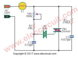
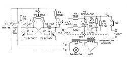
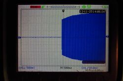
    Temperature "stabilizer" for transformer soldering iron

    Temperature "stabilizer" for transformer soldering iron

    These systems do not fulfill their function, especially with a triac, it is NOT a good idea to combine the inductance of the transformer and the system that generates chaff from the sine wave. Seemingly it works, but the transformer works in very unfavorable conditions.

    The word "stabilizer" is quite exaggerated because the system does not stabilize anything but "cleverly" reduces the temperature of the soldering tip.

    ATTENTION - I do not recommend the design for inexperienced people - there is a risk of electric shock, the whole system is under 230V mains voltage.
    Take special care when performing the layout and testing.


    Probably all users of a transformer soldering iron noticed that soldering with such a soldering iron requires a lot of practice in order not to cause losses with too high temperature.
    The problem is the lack of control over the tip temperature, closely related to the time the soldering iron is turned on.
    I decided to fix it a little bit. The first step was to check how the transformer soldering iron behaves when the supply voltage is lowered.
    For testing, I used a soldering iron originally adapted to 220V - this is the only one I have.
    The tests were performed using an autotransformer with smooth voltage regulation from 0 to 250V.

    By lowering the voltage in increments of 10 V, I checked whether it could be soldered, I reached a voltage of 170V at which my soldering iron practically stopped melting tin.
    At 200V, I did not notice any problems with soldering, but I noticed that even longer heating of the soldered place does not degrade the PCB as with 230V.
    The conclusion is obvious - lower the voltage supplied to 200V, a good solution would be the automatically decreasing linearly lowering voltage of the soldering iron in about 1 second from 230 V to 195-200 V. Why so - to quickly warm up the tip and then just keep it its temperature.

    I came up with the idea to use a programmable zener diode for this purpose, i.e. a very popular TL431 integrated circuit.
    The circuit works as a power zener diode according to the manufacturer's application, but how to increase the voltage linearly to 0 to 30V?
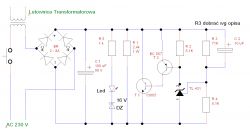
    Therefore, I made small changes to the typical scheme in order to obtain the effect of a linear voltage ramp.
    Temperature "stabilizer" for transformer soldering iron

    The test version looked like this.
    Temperature "stabilizer" for transformer soldering iron

    The system is connected in series with the soldering iron in the primary circuit of the transformer and it reduces the voltage supplied linearly by about 33V (this voltage must be selected for your soldering iron).
    The divider setting the stabilization voltage is selected for a voltage of about 31V (the R3 resistor turned out to be 71 K for me), it suggests trying to start with a lower value. The 31V voltage is almost the maximum operating voltage of this system.
    Higher voltage can be dangerous for the TL431 chip - different manufacturers list 30 to 37 V max.
    How the circuit works - please pay attention to C2 - the speed of voltage rise depends on it.
    The voltage rectified by the rectifier bridge charges the capacitor C1, which gives almost a short circuit in the first fraction of a second (voltage loss only on the diodes).
    The voltage begins to build up on C1, which causes the capacitor C2 to be charged simultaneously, the charging current C2 causes almost full voltage at input TL431 equal to the voltage at C1. The TL 431 circuit drives the transistors which limit the voltage on C1, but the capacitor C2 continues to charge and after a while it becomes charged, the circuit reaches equilibrium and the voltage set by the divider R3 / R4. As I wrote above, it is about 31 V. The power transistor must be screwed to a small heat sink, about 12-15 W is lost on it. The fact that only during the operation of the soldering iron a few seconds but seconds to seconds and it gets warm.
    The diagram also shows a diagnostic detail whether the system is working, it is a 16V zener diode connected in series, a LED and a current limiting resistor. The LED diode turns on when the voltage reaches about 20V, which indicates that the system is working.
    During construction and testing, it can be done safely, it is enough to use a power supply with a voltage regulation of 20-40 V and, for example, a 12 V / 5W car bulb connected in series. this will allow the voltage to be established safely.

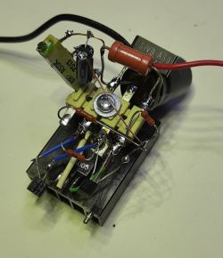
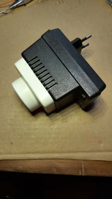
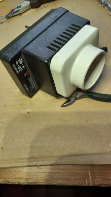
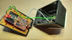
    The whole thing was built in an old housing after a plug-in power supply with an added socket. Therefore, it is an independent module to which soldering irons can be attached as needed.
    Temperature "stabilizer" for transformer soldering iron

    Temperature "stabilizer" for transformer soldering iron

    Temperature "stabilizer" for transformer soldering iron

    Cool? Ranking DIY
    About Author
    oldking
    Level 32  
    Offline 
    oldking wrote 1849 posts with rating 424, helped 150 times. Live in city Bytom. Been with us since 2003 year.
  • #2
    Anonymous
    Level 1  
  • #3
    Damian_Max
    Level 15  
    Heh, good xD.
    All the more so: if 30V is so important to you, it can be especially useful when you have a solar farm (or in the vicinity), although then it would be useful to sometimes reduce 50V.
    From the approach, I understand that you did not want to interfere with the soldering iron itself, so that the device can be connected to another soldering iron / or even a different device.
    Probably by winding several dozen / several hundred additional coils on the primary winding, it would also be possible to obtain an analogous effect, but it is more difficult to debug xD; but a two-stage trigger could be used, the first click would be from the new tap and the harder click would be from the original coil.
  • #4
    CosteC
    Level 37  
    I do not see the temperature sensor - it is rather a POWER LIMITER for a TRANSFORMER SOLDERING IRON.
    I admire the amount of effort in relation to the result .. You could also give 2 24V bulbs properly selected ...
  • #5
    Anonymous
    Level 1  
  • #6
    Anonymous
    Level 1  
  • #7
    398216 Usunięty
    Level 43  
    Everything is fine, I am glad that the system works, but I am bothered by one question (my colleague above also partially noticed this) - what will happen when you replace the tip and its parameters change? Please do not tell me that you have all the same tips, because you will not be - especially when (as probably all of them), instead of buying, you do it yourself with the wire you have at hand.
    All you need is a different minimum length, a different diameter, more contaminated copper, no contact on the screws or simply a larger copper field on the board and from soldering the threads. So it needs to be rebuilt in such a way that the voltage can be changed depending on specific needs. You even have a switch in the housing - it could be used for this purpose. However, I like the sentence:
    oldking wrote:
    These systems do not fulfill their function, especially with a triac, it is NOT a good idea to combine the inductance of the transformer and the system that generates chaff from the sine wave. Seemingly it works, but the transformer works in very unfavorable conditions.
    - many "young" (and unfortunately not only) electronics do not take it into account.

    Overall - if in your case this method of lowering the voltage works fine. However, due to what I wrote earlier, it is not a perfect solution, just as the transformer soldering iron itself is not perfect. Yes - for occasional service work - a very good invention: It heats up quickly (a few seconds and you can work) it cools down quickly (which is also not insignificant), it consumes electricity only when it is turned on (i.e. only when it is used), but it has too much (for me) inconvenience: Heavy weight, trouble with tips (they often burn out) and no real temperature stabilization. I had a transformer soldering iron myself (for repairs "in the field" - in exceptional circumstances) but to work with it on a daily basis? In life. I agree that there are users who have a different opinion - I know that. But if they tried to "change" to another - to a station with real temperature control, with replaceable (long-lasting) tips of various shapes / sizes, and if they had a comparison - they would agree to me.
    Quite simply - the transformer soldering iron was invented for other applications and you have to accept it. And any attempts to force her to behave differently than is "written in her genes" is pointless and in practice will cause more problems than good. Currently, really good soldering stations are not that expensive to combine - so let's leave the transformer for the outgoing service, and choose something from the wide range of soldering stations for everyday work.
  • #8
    oldking
    Level 32  
    jjan46557 wrote:
    Simple and useful.
    I will add that the R1 resistor shortens the time to return to the starting position.


    That's right, I was curious if anyone would notice what he was for - congratulations.
  • #9
    krzbor
    Level 25  
    Beginners should pay attention to one more aspect of the construction of this system - it should be very carefully checked before the first start-up, not only visually, but also with an ohmmeter. Lack of connection or contact in many places of the system will destroy the whole. It won't work on a "not working so I'll check and fix" principle. The following rule applies in this system: the sapper makes a mistake only once :)
  • #10
    Janusz_kk
    Level 36  
    That's why I took the easy way and I have the soldering iron connected to the autotransformer set to 200V. An accelerated start is not needed, you just wait a few seconds longer for the tip to warm up.
  • #11
    Anonymous
    Level 1  
  • #12
    krzbor
    Level 25  
    spec220 wrote:
    You exaggerate ... It is enough to put a suitable zener diode in parallel to E and C of transistor T2, or some resistance divider on the base of T1 and it is much safer ...
    Since you correct the layout and write that it will be much safer, it means that I am not exaggerating :)
    I do not write that the circuit is bad - just if T1 does not limit the voltage, there will be problems. The fact that it will not limit can be triggered in many ways - the easiest way is by forgetting one of the connections.
  • #13
    Anonymous
    Level 1  
  • #14
    pawelr98
    Level 39  
    Janusz_kk wrote:
    That's why I took the easy way and I have the soldering iron connected to the autotransformer set to 200V. An accelerated start is not needed, you just wait a few seconds longer for the tip to warm up.


    The same can be achieved by using an ordinary 230V / 24V mains transformer.
    When working in such short pulses, it can even be a small, temporarily overloaded transformer. Network transformers, when connected in series with the network, work as an auto-graph increasing or decreasing the voltage of this winding by the value of this winding.

    On the other hand, instead of linear or phase control, you can simply switch on full sine waves using a counter that controls the triggering of the triac.
    Every few full periods comes one and that's the case.
    This diagram with a multivibrator would be "almost good" if it were not for the fact that it can turn on one half cycle and not the other half, causing the transformer to under-magnetize the DC component. The described parts are switched on at zero, but this does not protect against the appearance of the DC component in the supply voltage, because there is no guarantee of switching on two half-periods one after another.
  • #15
    pikarel
    Level 36  
    I already thought that the TL431 you control the thermistor located on ... well, you can't attach anything to the tip here :)

    I also used to think about stabilizing the tip temperature in a transformer soldering iron (hereinafter LT), but it was over; I regulate the temperature of the LT tip with a microswitch (those in LT are durable and of good quality).
    I also solder the Solomon flask for years, but only small plates, SMD or something serial; Once established, the temperature to make several hundred soldering points in the assembled device makes the work much easier (the flask is lighter).
    I use LT every day and I'm really comfortable with it.

    The granddaughter followed in his grandfather's footsteps and bought himself a Solomon.
    He recently asked me to teach him how and when to "snap" LT so as not to overheat the tin.
    Wow, Lord, what a clever beast, this grandson of mine; it solders nicer than me!
    :)
  • #16
    szeryf3
    Level 26  
    Very interesting layout and at one point I was thinking about duplicating it for my soldering iron.
    However, I will still stick to the old structure.
  • #17
    minus3db
    Level 11  
    Thanks for the idea! It is a bit tiring that someone "knows better what is good" and recommends "buy a station, what do you need a transformer". Or maybe who just has a station (for 30 years, there was Elwik, there was Solomon), and the transformer just likes it and has been using it for decades - and has no problem with soldering with such a soldering iron? I soldered a lot with electron tubes: the sockets meant a very high heat capacity, the wires were thick, the feet of resistors or Elwa electrolytic capacitors - also. Yes, I am that weirdo who, having a very good station for a few hundred, still uses the transformer more often. I do not solder SMD, and for THT (including germanium and cuprite elements) the transformer served me without any problems, especially with the so-called "eternal (sharp) points". So much for Grandpa Boomer's nagging :)

    I like the solution because I used (since this year I no longer solder for health reasons) a similar idea, but with the use of a "anti-phase" transformer on 12/24 / 36V / 60V (I inherited from Dad - wound up for ages back to the battery charger) for coarse voltage adjustment. And then I bought a regulator-stabilizer (magnetic) for televisions, where you could easily change the voltage from 190 to 240V. Finally, I reworked the soldering iron with a 45 / 75W switch (I added a lever) so that you could "add power" at the start with your thumb and then stay at 45W, or lock to 75W (as in the original) for thicker jobs.
  • #18
    Karol966
    Level 31  
    I use the ST50 pace station every day, I solder quite a lot on it (maybe not every day, but still) and although as it is a pace, it heats up in several seconds, I often use a transformer and nothing can replace it, because the temperature of the tip is reached in a few seconds . It is best when you need to quickly solder 2 wires or replace a larger / threaded element (which is somewhere far from the delicate semiconductors - I'm afraid of a strong electromagnetic field at the tip). Well, if I rarely use it, the tip still needs to be replaced every short time (and I have an old version, which has screwed connectors immediately after leaving the housing, so it is even more difficult to replace the tips and their non-standard thickness), so too I was thinking for a while about building a temperature stabilization system, but literally a stabilization system. I did not come up with any specific idea, but then I thought to measure the voltage at the tip (which certainly changes, I wonder to what extent) or to measure the primary winding current through a current transformer. On the stubborn one, you could also measure the current on the secondary (how many amps can there be, 100? Then such an ACS758 would be enough, but it costs a bit, but you pay for convenience, right?)
  • #19
    Anonymous
    Level 1  
  • #20
    tmf
    Moderator of Microcontroller designs
    Moderated By tmf:

    I deleted off-topic posts. This is a DIY department, not a garbage can. People writing off the topic, or simply trolling, will be rewarded according to their merit.

  • #21
    krzbor
    Level 25  
    So I look at the schematic again - transistors T1 and T2 have no base current limitation. Could this be so?
  • #22
    yorgus_1978
    Level 9  
    A system could be made on the AVR and optotriac, the controller would be powered from the bulb winding (after rectification and stabilizer), the controller would measure the voltage at the tip
    (it is usually between 0.1-0.2V). And now, as you know how the resistance of copper varies with temperature, it would suffice to do that when the measured voltage at the tip increases
    e.g. 2 times in relation to that recorded at startup, the system with a triac will lose mains voltage cycles (group control).
    The controller here gives it that it can measure the voltage after waking up, and regardless of the resistance of the tip (its diameter and length), calculate the moment at which to leave the switch on.
  • #23
    398216 Usunięty
    Level 43  
    yorgus_1978 wrote:
    the controller would measure the voltage at the tip
    (it is usually between 0.1-0.2V). And now, as you know how the resistance of copper varies with temperature, it would suffice to do that when the measured voltage at the tip increases
    Calculate the resistance of the tip in the cold state, and the resistance in the hot state, and after subtracting the higher resistance from the lower one, consider how precise and sensitive such a controller would have to be to reliably stabilize the temperature of the tip.
    In addition, tips in transformers are screwed to copper flat bars; the copper itself gets covered with tarnish / oxide or other quite quickly, and this changes (sometimes quite a lot) the resistance of the contact itself. Where would you like to take the test voltage to the controller from? From the very tip? Is it from the ends of a flat bar? In my opinion, neither one nor the other method would ensure sufficient precision and stability of the test voltage.
    I'm afraid that you "hit" the idea without thinking about the realities.
  • #24
    Anonymous
    Level 1  
  • #25
    krzbor
    Level 25  
    spec220 wrote:
    In this solution, it can be ... (the "resistor" is a series connection of the load with the system)

    It is not about the load, but about limiting the base current of both transistors.
  • #26
    oldking
    Level 32  
    krzbor wrote:
    spec220 wrote:
    In this solution, it can be ... (the "resistor" is a series connection of the load with the system)

    It is not about the load, but about limiting the base current of both transistors.


    You will limit the base current - and after stabilization.
  • #27
    Anonymous
    Level 1  
  • #28
    yorgus_1978
    Level 9  
    398216 Usunięty wrote:
    yorgus_1978 wrote:
    the controller would measure the voltage at the tip
    (it is usually between 0.1-0.2V). And now, as you know how the resistance of copper varies with temperature, it would suffice to do that when the measured voltage at the tip increases
    Calculate the resistance of the tip in the cold state, and the resistance in the hot state, and after subtracting the higher resistance from the lower one, consider how precise and sensitive such a controller would have to be to reliably stabilize the temperature of the tip.
    In addition, tips in transformers are screwed to copper flat bars; the copper itself gets covered with tarnish / oxide or other quite quickly, and this changes (sometimes quite a lot) the resistance of the contact itself. Where would you like to take the test voltage to the controller from? From the very tip? Is it from the ends of a flat bar? In my opinion, neither one nor the other method would ensure sufficient precision and stability of the test voltage.
    I'm afraid that you "hit" the idea without thinking about the realities.


    The tension can be measured on the screws, the measurement will be almost 4 contacts, after all, we only measure the tension. What would have to be a precise ADC?
    After all, I wrote, it would have to distinguish 0.1 from 0.2V every 10ms (max voltage). This is what even the ADC in the AVR can do with the significant
    surplus. The accuracy of the soldering iron is not perfect, and it is not a voltage source, there is a large dissipation inductance.

    If you have a transformer and a digital oscilloscope, see what it looks like. As for copper oxides - they are semiconductors,
    and if it were as you think, the current through the tip would not flow almost at all. Copper does oxidize, but not at the point of contact
    (in which there is a maximum of several dozen degrees - a flat bar conducts heat well).
  • #29
    Janusz_kk
    Level 36  
    I would not measure the voltage on the tip at all, but if it was on the bulb winding, I would measure the current on the primary through the transformer.
  • #30
    yorgus_1978
    Level 9  
    I just checked - the change between cold and hot is like 125 to 175 mV. No problem to recognize. (Probe is x1)
    The soldering iron is a solder, 1.5mm tip ^ 2.
    Temperature "stabilizer" for transformer soldering iron