The topic is related to:
edu elektroda.pl # 04 operational amplifiers - LED current stabilization FAQ LED flashing to the beat of the music 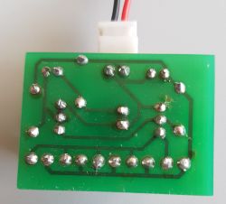

As you can see, a lot of space is devoted to LED flashing to the rhythm of the music and why set up a new, related topic? The reason for this is the designed chip, the Chinese putty, which needs the fewest parts for this. The presented diagrams in related threads are more advanced, complex and may have other possibilities, while the unique feature of this kit is its minimalist design, with the same effectiveness. I wouldn't like to use phrases like "the beauty of design" here, but the design is really well done, despite the suspicions of LED or output transistor burnout. You can see that it is a well-thought-out design, even though it is simple, but the simplicity is the result of good knowledge of electronics.
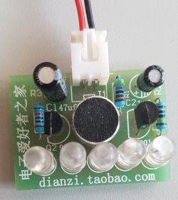
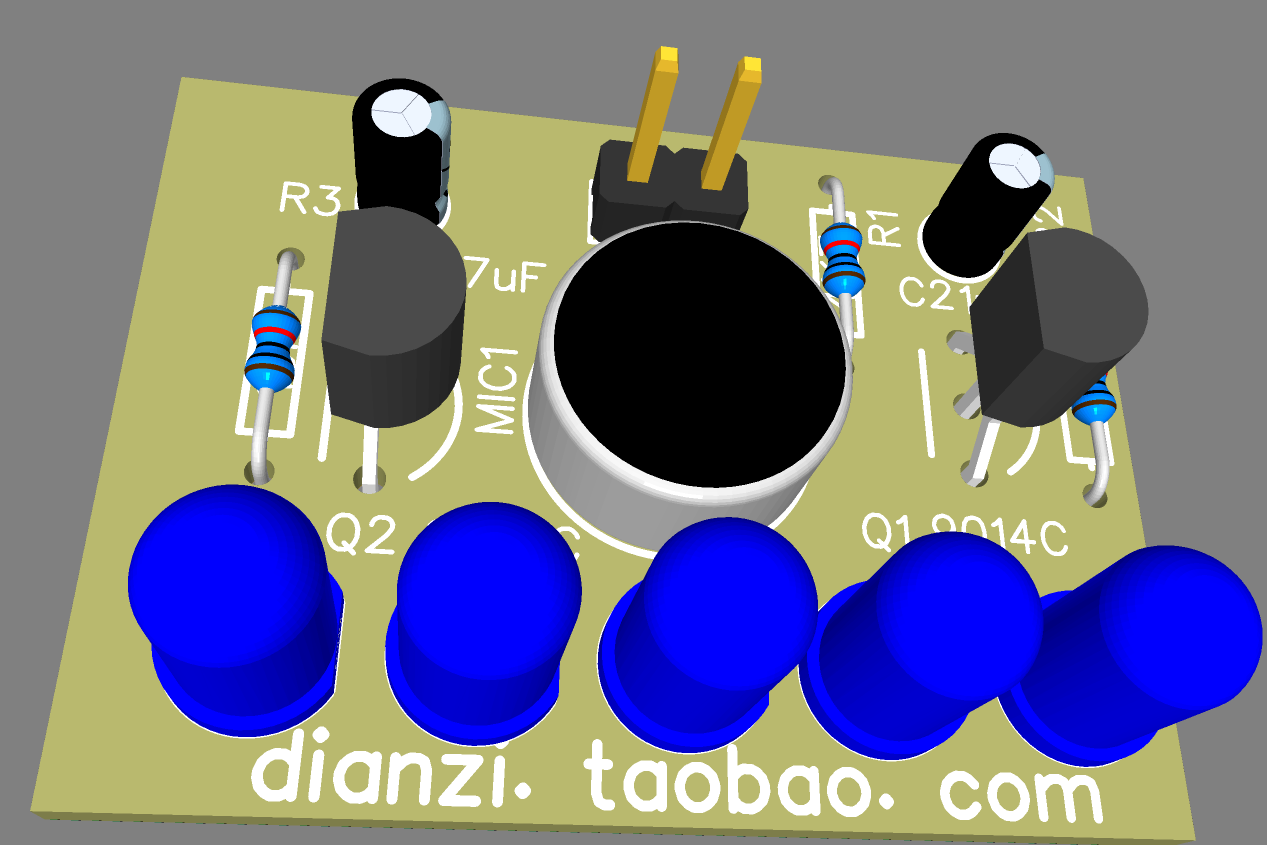
To pulsate the LED to the rhythm of the music, the author only needed:
3 resistors
2 NPN transistors
2 capacitors
Microphone
LED lights
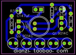
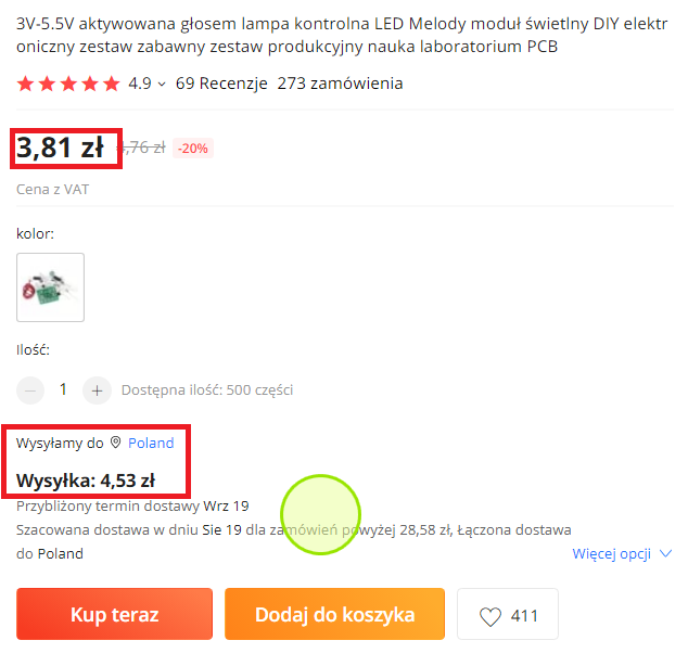
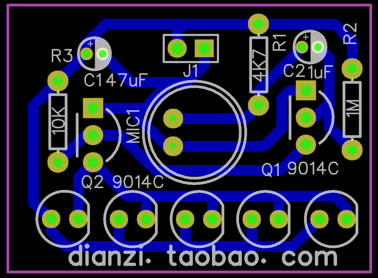
The size of the PCB is 34x25 mm (one-sided).
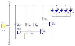
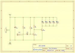
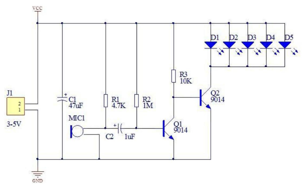
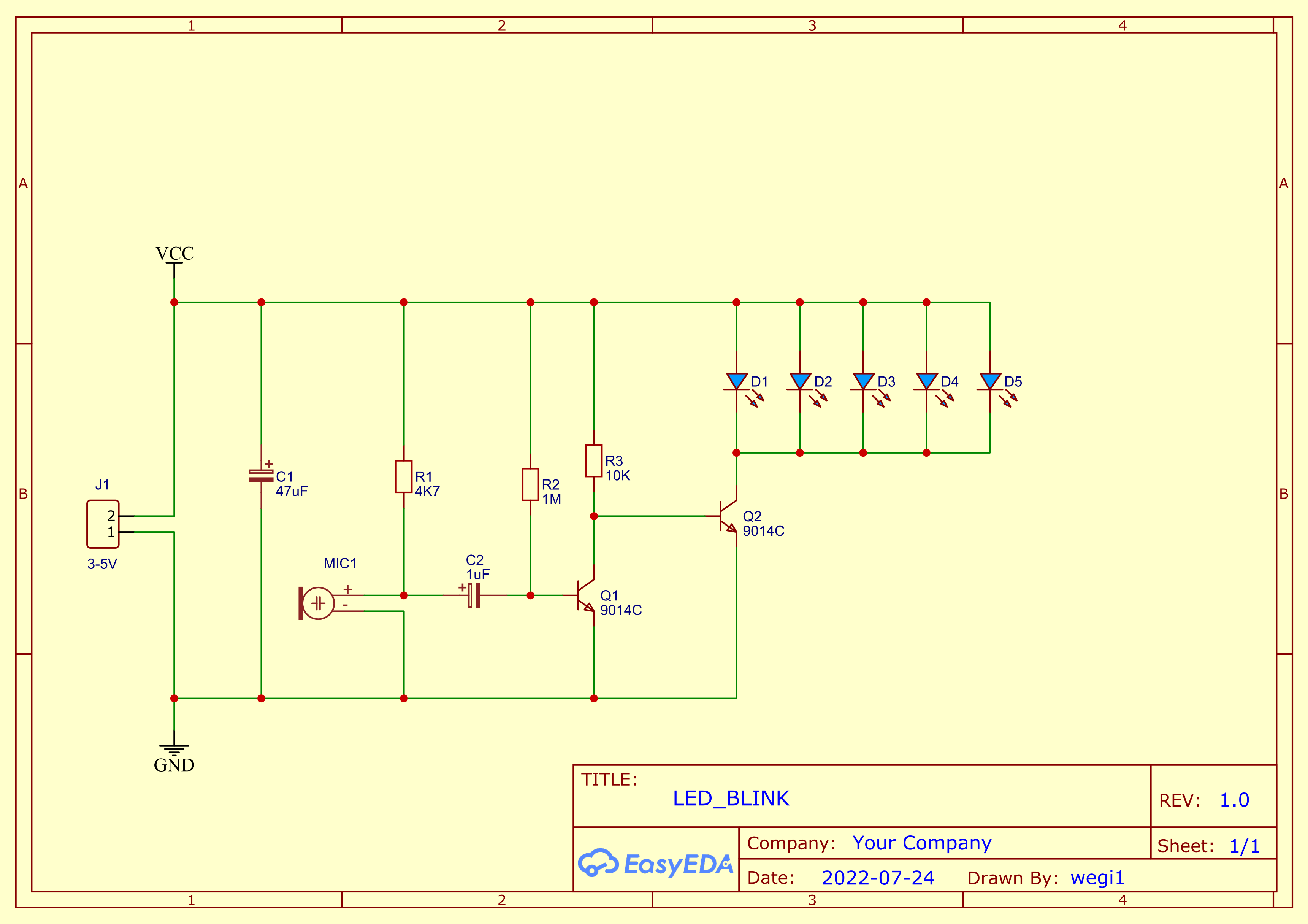
Diagram:
I decided to check the suspicion of excessive current that could damage the diodes or the Q2 transistor (NPN 9014) by measuring the current consumption of the entire system at rest and during the highest load:
- at rest, the system consumed less than 1 mA [milliampere]
- with the greatest possible noise that I was able to produce 91 mA [milliamps], which is unrealistic, because even by directly rubbing and tapping the microphone itself, the intensity did not exceed 80 milliamps.
The manufacturer foresaw the possibility of supplying 3 to 5 volts, I measured the consumption at 5 volts to measure the worst case.
Having two values - supply voltage and current intensity - using the simplest formulas, you can calculate the circuit impedance and the power dissipated.
Calculating the impedance from Ohm's law:
R = U / I = 5V / 0.091A = 55?

Now that we have made an effort to calculate the impedance, we can calculate the power of the circuit:
P [W] = I * I [A * A] * R [?] = 0.091 [A] * 0.091 [A] * 55 [?] = 0.45545 [W] ?0.45 [W]

In fact, you didn't even have to work hard to calculate the impedance, because having the value of the consumed current and the supply voltage, you can calculate the power consumption using the formula:
P [W] = U [V] * I [A] = 5 [V] * 0.091 [A] = 0.45545 [W] ?0.45 [W]

Knowing that the current consumption by the system at rest was negligible, it can be seen in the diagram that the transistor Q2 9014 is the most loaded element.
In any case, we have two important results to try to verify the load on the circuit:
1. Power 0.45 W
2. Maximum current 0.091 A
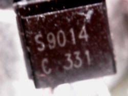
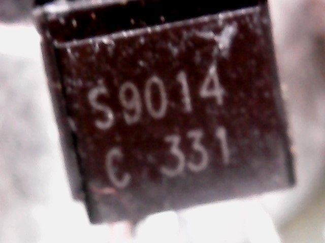
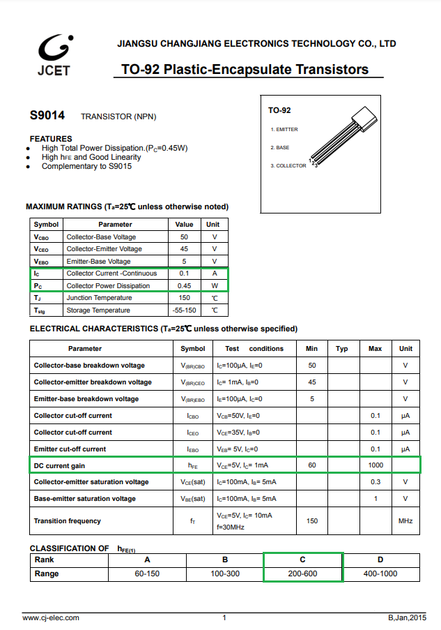
Having the product card from 9014C (I checked, they are installed"C" versions

you can look for 3 parameters of this transistor:
1. The maximum current that can be "passed" through it = 0.1 A
2. Power dissipation 0.45 W
3. You can take a look at the HFE, although this is just for reference as the spread is too large (200-600).
 We do not exceed the maximum current of the transistor
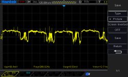
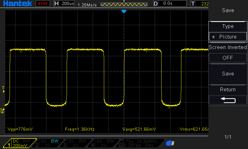
 , in fact it does not exceed 80 mA, the power dissipated is like a pin, we must know that this power is not all the time, but at the highest peak in the voice wave chart. My point is this is not a continuous load as you can see in the oscillogram taken from the collector of output transistor Q2.
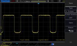
By the way, you can see what the microphone signal level looks like.
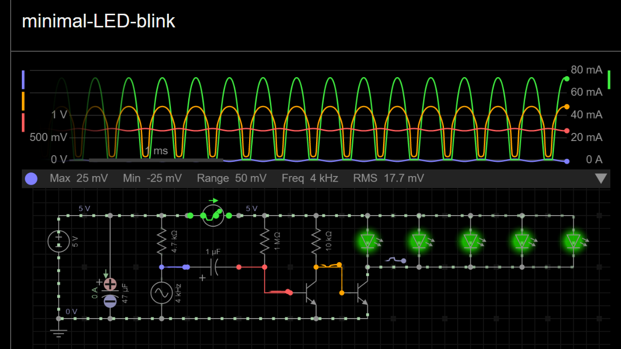
The layout is very simple and can be simulated, see below for simulation link.
https://everycircuit.com/circuit/4631294967021568/minimal-led-blink Simulation screenshoot:
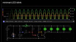
You can see that the signal from the microphone oscillates around the mass of ? 25 mV. After cutting the DC component downstream of the 1 uF capacitor, the oscillation is still 50 mVpp, but it has moved to 0.75 V by biasing the base with a 1 M? resistor and controls the base of the transistor. At the collector Q1 and the base of Q2, the signal oscillates from 0 to over 1 V alternately opening and closing the output transistor Q2, which has a polarized base through a fairly large 10 K resistor, thanks to which Q2 will not enter a state of deep saturation. By using such larger resistors, you can minimize the number of components and you don't need to use a collector-emitter current limiting resistor, that's the trick.
More or less, but rather more, it should be assumed that the currents flowing through D1 to D5 are proportionally divided into 5 equal currents, so that we do not exceed the current that could damage the LEDs. 90 mA (in peak) divided into 5 diodes does not even exceed 20 mA. In this way, we came to the point that we know that we can be confident about the most loaded elements of the circuit, the Q2 output transistor and LEDs, although it must be admitted that we had to think about it a bit.
Whatever the inaccuracies and distortions this circuit has, we need to know that it does not transfer the voice for listening, but uses the voice signal to flash the LEDs, for which the circuit is perfectly sufficient.
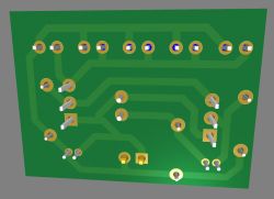
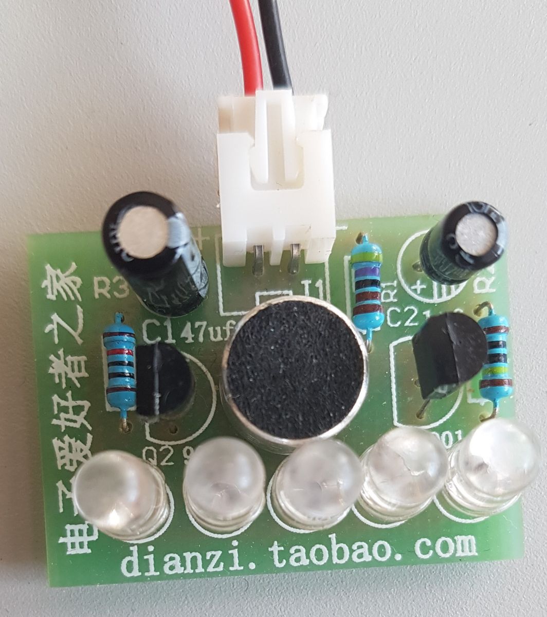
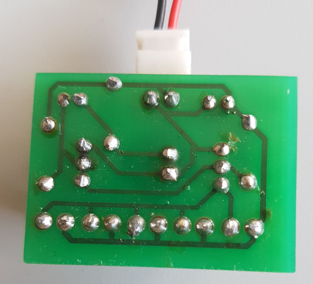
Since the system is very simple to build, and at the same time it is quite unusual, it is not difficult to make it on a PCB:

A video showing how the system works.
[movie: d56c788336]
https://filmy.elektroda.pl/79_1658700405.mp4 [/ movie: d56c788336]
Gerber files in the attachment, if someone would like to order the PCB of the discussed system.


Comments
Diversity is always a good approach, sometimes complex articles appear and sometimes reviews of simple products. Interestingly, in simple projects there is often a lot of room for experimentation, there... [Read more]
Nice little layout. I see you've figured it out in every possible way. [Read more]
Agreed, it is a pity that the author did not notice the disadvantages of this solution. It will work because there is no other option, but it is far from ideal - to act with meaning. All in all, it's... [Read more]
It is not exactly the minimum set to "blink" in rhythm. Who remembers the 90s knows that the first "effects" of this type appeared along with the so-called "dachshunds" where the diodes were directly connected... [Read more]
Hello forum members On the subject and the layout itself, as a freshman, I have a question. I would like to make such a sound spectrometer, but in the macro version, i.e. not with 5 LEDs but with 30,... [Read more]
https://obrazki.elektroda.pl/5489109100_1659085676_thumb.jpg https://serwis.avt.pl/manuals/AVT2864.pdf https://youtu.be/aWjGKESF4fM https://sklep.avt.pl/avt2864.html It's hard to do it analog... [Read more]
Having grown up children, nobody expects gifts for themselves, and here you are: https://obrazki.elektroda.pl/3297772300_1659616788_thumb.jpg Many thanks to Elektroda Team. [Read more]
No problem, we recommend ourselves for the future and invite you to the next presentations :) [Read more]