Greetings!
I have bought Spectrum Smart E27 1500 lm 13 W (Model: WOJ14473) and want to share my teardown.
I find confusing some disassembly manuals so firstly let me share my way.
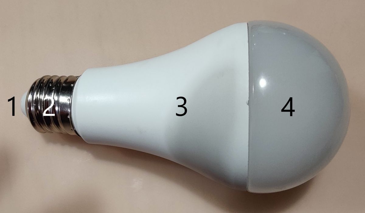
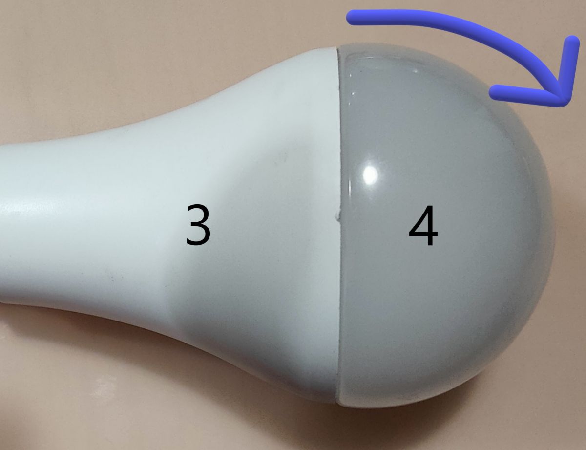
External parts are:
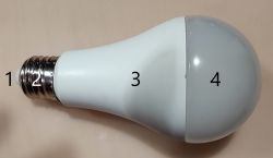
1 - Tip/Pin
2 -E27 thread with plastic hole for Tip/Pin [1]
3 - Plastic body
4 - transparent cover/diffusor
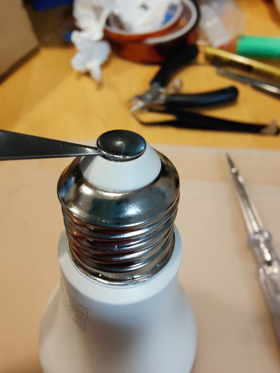
Disassembly
First put something sharp between Tip/Pin[1] and part [2]
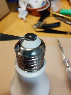
Pull Pin [1] out of plastic [2]
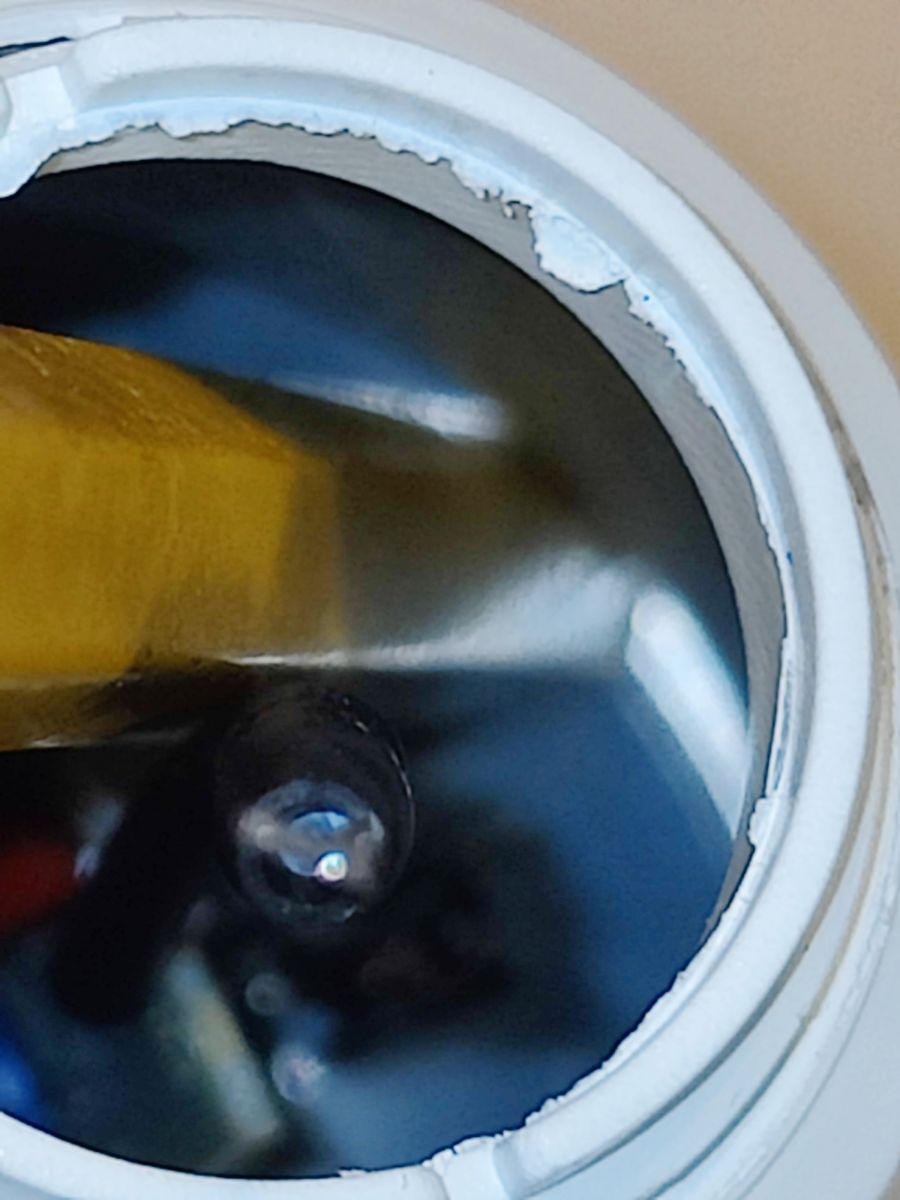
Then You will see one of live connections:
 Notice this as it has to be in place during assembly.
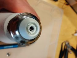
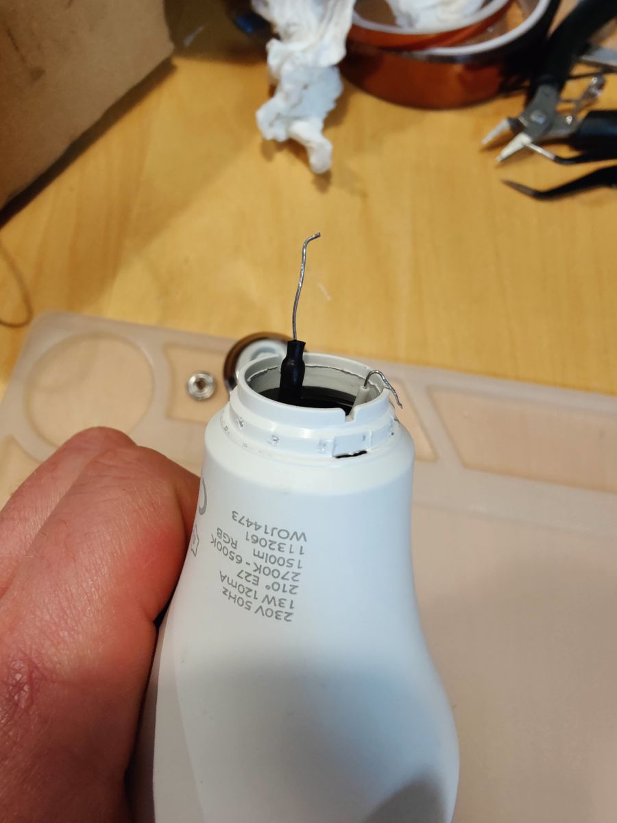
This is tricky part as metal that this thread is made of is pretty thin I would suggest to put something betweet metal part of thread [2] and plastic body [3]. I have used lock-jaw pliers and covered thread with rag but thread is slightly deformed.

There is second connection wire.
Another thing to notice is that after assembly this part will no longer hold as it previously did. You can try to pin original holes all around body to ensure good contact.
There are diffrent ways of removing diffusor . For this bulb running thin sheet of metal between body and diffusor was no help because putty is at its botom part of diffusor .
I manage do detach it by grabbing body with one hand and diffusor and apply force (first disassembly needs it a lot) like so:

Some people on internet find it easier to use twisting motion.
I think that most important thigs is to place Your fingers.hand evenly on whole parts, to avoid damaging parts or Your hands.
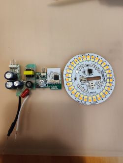
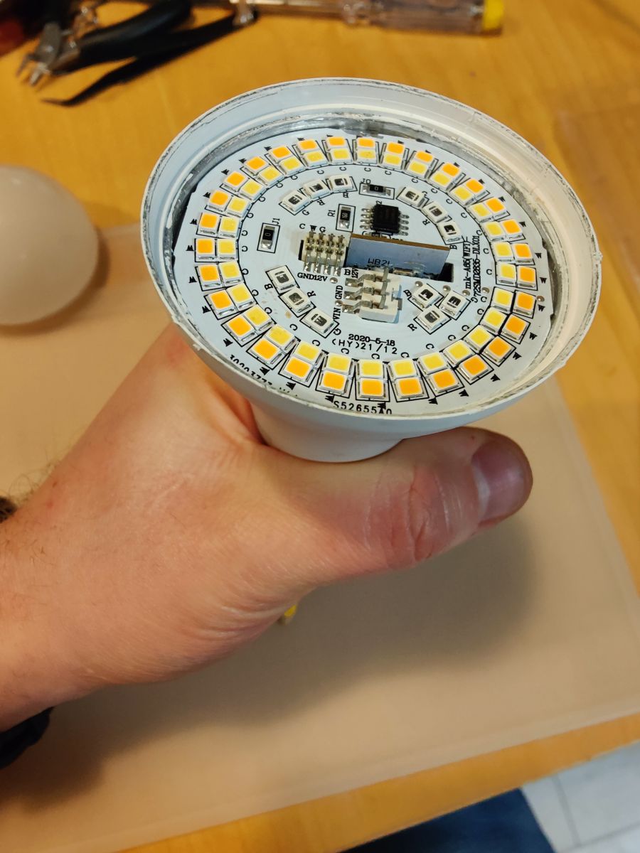
You will notice aluminium plate with LED on it.
Turn Your bulb upside down. Put something relatively soft and long inside avoiding any internal electronic PCB parts". I recommend wooden crayon.

Turn You bulb once more for the the other part to crayon to hold on something (table).

And tap external part {3] (not the LED plate in center) with Your straightened hand.
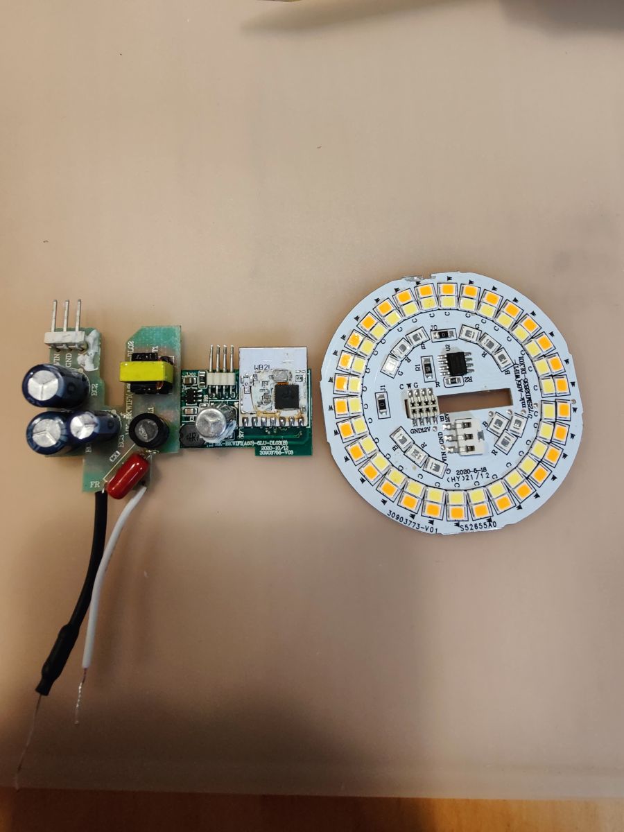
You will see 2 PCB (power PCB and MCU PCB) and LED plate.

Originally there was some putty additionally holding it together. Remove that carefully with scalpel and avoid braking SMD parts.
After that just slide one PCB from another.
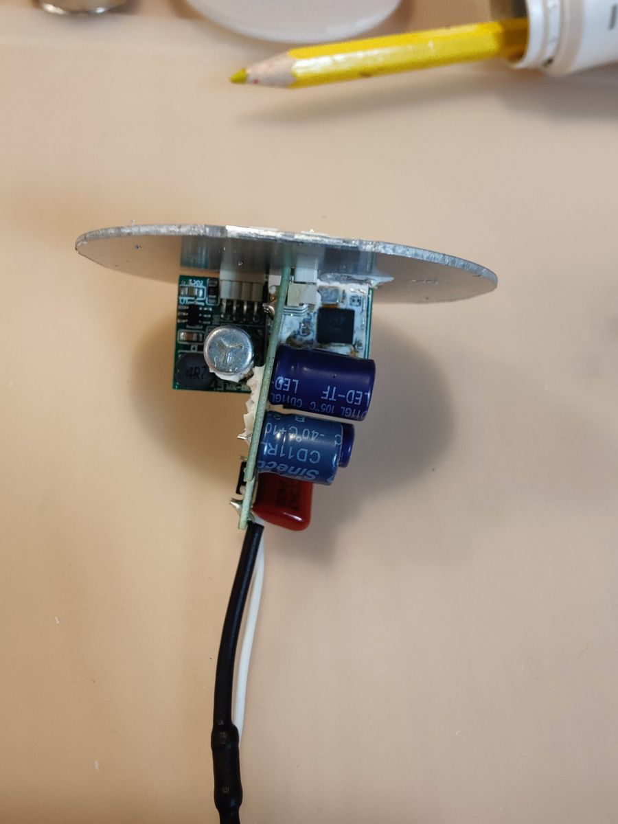
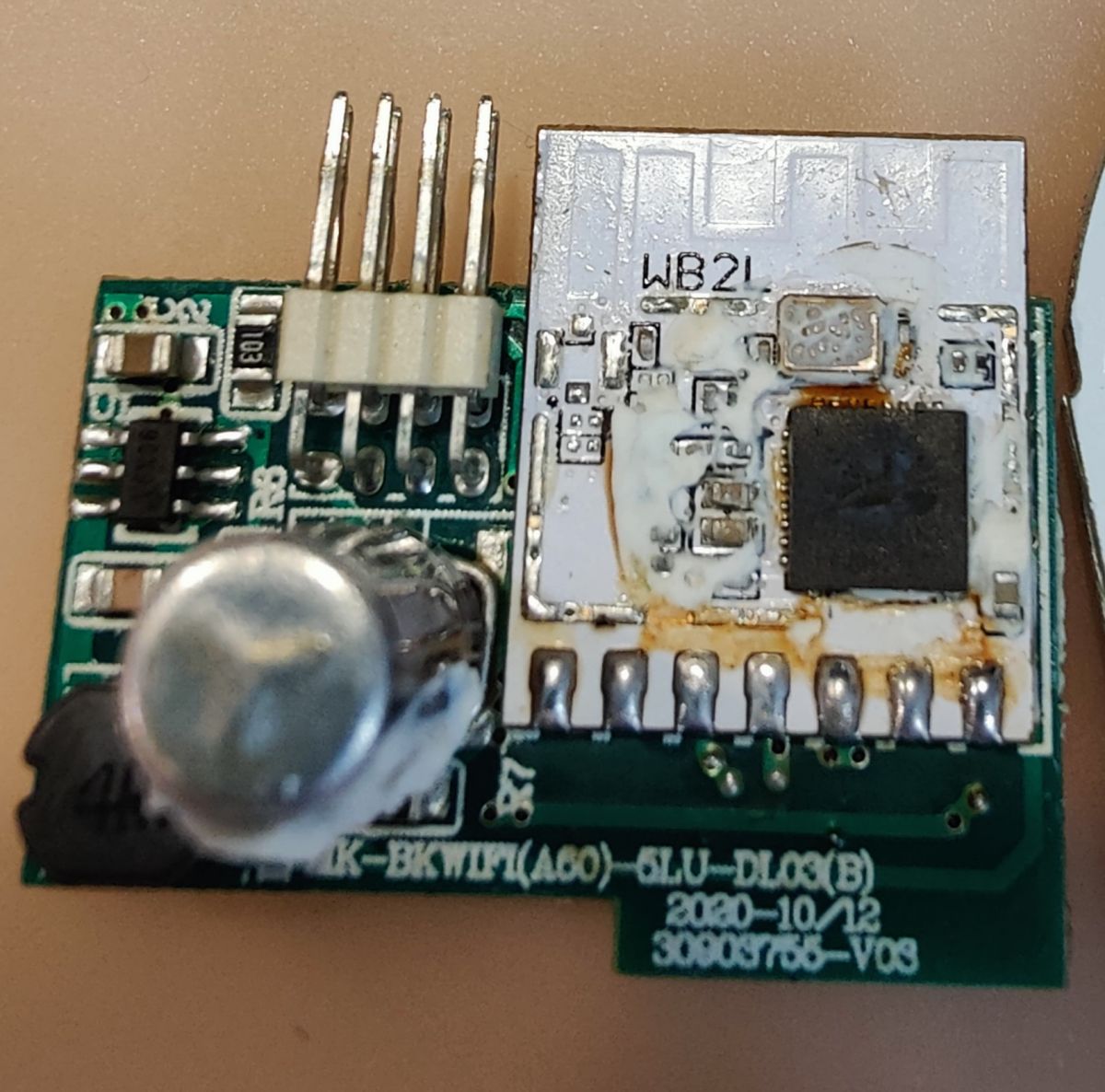
Next aim is to desolder (use soldering iron or more preferentially hot air) W2BL PCB because TX and RX is on back of PCB.

(Yeah I know something looks rusty. Cleaned it after that.)
Programming
Connect:
Programmer / WB2L
- 3v3 to 3V3 pin*,
- GND To GND
- Left loose to RST (also refered as CEN)
- TX to RX
- RX to TX
* I have used FTDI programmer with 3V3 output so no additional power supply was required.
Use
BK7231GUIFlashTool
Pic COM port.
Pic BK7231T.
Downlaod FW *.bon file manually or from inside program.
Flash It.
Configuration
P6 (PWM0) Set up as PWM #2
P7 (PWM1) Set up as PWM #5
P8 (PWM2) Set up as PWM #4
P24 (PWM4) Set up as PWM #3
P26 (PWM5) Set up as PWM #1
* what i have in fact did is i have choosed
this device as it seemed similar and swapped PWM 3 i 2.
I additionally advise You to set up Flag 12 from WebUI to restore bulb to previous state after switching off and back on.
Put everything back together reverse order keep in mind:
- live wires should have good contact with their pin and E27 Thread.
- placing back aluminium plate with LEDs require additional use of force to put it back evenly into body;
- E27 thread can require pinching hole to provide reasonable friction (You will notice this if when screwing bulb thread will stay in bulb socket and rest of bulb will stay in Your hand - Yest pretty hazardous since live wires will come loose ...)
I personally did not saw need to place putty again;
Right now I have some
issues (submitted on GitHub)it takes long time to reconnect bulb to WiFi. If You have some similar problems You can try to Use feature called Ping Watchdog.


Comments
Very detailed presentation, thank you. Regarding WiFi issue, we'll be looking into that soon. It's possible that in some rare cases devices might have bad calibration data. Altough... you're saying that... [Read more]
I have fixed this by editing. Also I did add the my initial method for other users. [Read more]
Thank you. For the E27 base, I found someone in YouTube heating the base for a 1.5 minute with a lighter and it comes off easily with the heat. I destroyed my E27 base the first time, and I used a... [Read more]
Searching Aliexpress for E27 bases.... wait, you mean just the base part, as a replacement? At first I was confused and i thought you are looking for entire bulbs. I haven't seen anyone selling E27... [Read more]
Yes, I was looking for just the screw part but didn't find it. I've seen some Indian sites selling it but I don't think it's easily shipped worldwide from there From what I can tell the base is the same... [Read more]
I've found an old non-smart E27 bulb and it seems that it's using the same parts: https://obrazki.elektroda.pl/4297124600_1673875232_thumb.jpg https://obrazki.elektroda.pl/3155055300_1673875232_thumb.jpg... [Read more]
@pkaczmarek2 Yes, that what I did. I got another base from cheap bulb I also found a better way to remove the base, which leaves the E27 base and the bulb intact from any harm I have one of those... [Read more]
Found same bulb but with totally different electronics: based on BK7231N chip and CB2L. I was able to flash it with your instruction but unfortunately I can't find right configuration for the pins. Any... [Read more]
What is the marking here? https://obrazki.elektroda.pl/1030484900_1681338925_thumb.jpg [Read more]
The chip number is something like: KP18068 ANNAR 4.1 M42017 Letters are not sharp enough under magnifying glass so I will check it later under microscope. [Read more]
It seems that this product uses an integrated LED controller with a I2C-like protocol - KP18068. https://obrazki.elektroda.pl/6673106500_1681368242_thumb.jpg Sample bulb diagram: https://obrazki.elektroda.pl/3127432100_1681368300_thumb.jpg... [Read more]
That's interesting. I will test it on other chip drivers we will see how it's going to work. I bought this bulb on polish auction service - allegro. Seller: SPEC-KABLE link: https://allegro.pl/oferta/zarowka-led-e27-rgb-cct-13w-230v-smart-sciemnialna-13241216510 And... [Read more]
I can try doing driver remotely but we need to OCR images from there: https://www.sekorm.com/news/78758802.html http://www.kiwiinst.com/newsinfo/2765480.html?templateId=510705 I tried with one but the... [Read more]
OK. Here are some ocr readings with google lens. Let me know if it's worth something. https://obrazki.elektroda.pl/1657274200_1681401098_thumb.jpg https://obrazki.elektroda.pl/8881125400_1681401098_thumb.jpg... [Read more]
It doesn't look complete for me, but it is not a fault of your translation, but the whole page doesn't seem complete. I don't see the addresses of the registers like in SM2235, etc. It would be helpful... [Read more]
Any news about driver for that chip? I asked for technical support on the manufacturer's website http://www.kiwiinst.com/hqzc, we'll see if they respond. [Read more]
Recently we had LED on KP18058 (not on KP18068) and managed to do the analysis: https://www.elektroda.pl/rtvforum/topic3991620.html Maybe the KP18058 driver will also handle KP18068 ...? [Read more]
According to this user's report: https://github.com/openshwprojects/OpenBK7231T_App/pull/906 KP18068 and KP18058 have the same protocol. @linian can you check? [Read more]
Hi Gents. I bought what seems exactly identical bulb in my local shop. It is sold under a brand name "Eveready" Smart Bulb. It has BK7231N and KP18068 (ESSP) I2C driver, exactly the one you are talking... [Read more]