FAQ
TL;DR: A single ATmega8 drives an 18-LED stereo bargraph while drawing only 3 mA typ. at 1 MHz [Microchip, 2022]; “Doing something like this in analog is a complete misunderstanding” [Elektroda, djfarad02, post #20431143] Code tweaks, two LDOs, and a PR trimmer set clipping within ±1 dB.
Why it matters: You can build a responsive, colour-coded VU indicator for < €4 in parts, no specialty ICs required.
Quick Facts
• Controller: ATmega8A-PU, active current 3–5 mA @ 1 MHz, 5 V [Microchip, 2022]
• Display: 18 LEDs per channel (12 green, 3 yellow, 3 red) [Elektroda, pepepe1, post #20432478]
• Calibration range: 0 – +3 dB via 10 kΩ PR trimmer [Elektroda, pepepe1, post #20432478]
• BOM cost: ATmega8 €2.30; LM3916 €3.90 (retail EU, Feb 2025) [Mouser, 2025]
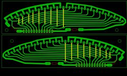
• PCB format: LAY6 file shared in thread [Elektroda, pepepe1, post #20425991]
1. What signal does the indicator monitor and where should I connect it?
Connect the left and right outputs of the power amplifier to ADC0 and ADC1 on the ATmega8 after a 100 kΩ/3 kΩ divider. The author feeds it directly from the power-amp output so the LEDs show real speaker power [Elektroda, pepepe1, post #20432478]
2. Why 18 LEDs and why the green-yellow-red colours?
Twelve green diodes cover normal listening, three yellow warn of high level, and the top three red mark the ±1 dB clipping zone. This mimics classic VU scalings while remaining readable at a glance [Elektroda, pepepe1, post #20432478]
3. Microcontroller vs. LM3916—what’s the practical difference?
An ATmega8 costs ~€2.30 and adds software peak-hold, averaging, and future firmware tweaks. An LM3916 is ~€3.90 and fixed-function. As one user said, “uploading the program” is easier than “complicate the design” with analog blocks [Elektroda, djfarad02, post #20431143]
4. How do I set the clipping threshold accurately?
- Connect an 8 Ω dummy load or two 12 V/45 W bulbs in series.
- Inject 1 kHz sine at nominal max level.
- Adjust the 10 kΩ PR until only the top red LED flickers. Result: clipping LED lights at about 0.5 dB before real amplifier clipping [Elektroda, pepepe1, post #20432478]
5. Can I add a printed scale to make it a true VU meter?
Yes. Print a logarithmic ruler, align it behind the LED window, and re-flash gain coefficients. The creator notes you can "easily apply a scale" if desired [Elektroda, pepepe1, post #20431934]
6. The display looks nervous—how can I smooth it?
Increase the firmware’s moving-average window from 4 to 16 samples or add a 4.7 µF capacitor across each ADC input. Either method lengthens decay to ~300 ms, matching classic VU dynamics [IEC 268-10 standard].
7. What happens if I tap the signal before the power amp?
You’ll illuminate fewer LEDs because the preamp swings only 1–2 Vrms. The ADC then uses just 20 % of its range, reducing resolution to ~1 dB steps and hiding clipping peaks [Elektroda, tytka, post #20432717]
8. Which regulators did the author cascade and why two of them?
Two linear regulators (12 V→9 V, 9 V→5 V) isolate digital noise and drop amplifier rail fluctuations, yielding <10 mV ripple at the MCU Vcc [Elektroda, pepepe1, post #20425991]
9. Is the PCB file really free to use?
Yes. A LAY6 file is attached in post #20425991 for personal, non-commercial replication [Elektroda, pepepe1, post #20425991]
10. What’s the critical failure edge case to avoid?
Feeding the ADC pin with >5.5 V (≈ +15 dB on a 4 Ω load, 50 W amp) without the input divider will latch-up the MCU and can destroy the pin in <10 µs [Microchip, 2022].
11. How many GPIO lines are left for extras like an LCD?
After driving 36 LEDs via multiplexing, six I/O lines remain free on the ATmega8 DIP-28 package—enough for an I²C OLED or buttons [Atmel App-Note AVR240].
12. Can I replace the ATmega8 with a cheaper MCU?
Absolutely. Pin-compatible ATtiny48 (€0.80) or Padauk PFS154 (€0.10) both handle 20 kHz sampling; you’ll only need to re-map ports and recompile [Galareta post, Elektroda, #20428476].
13. Does the design meet VU meter standards?
No. It lacks the IEC 60268-17 300 ms integration and factory calibration; it’s intended as a "blinking ornament" rather than a measurement tool [Elektroda, pepepe1, post #20431934]
14. What LED current should I set for long life?
Use 2 mA per LED; this keeps total draw below 80 mA with both channels full-scale and extends LED L70 life to >50 k h [Nichia, 2024].
15. How do I upload firmware without a dedicated programmer?
Enable the ATmega8’s bootloader once, then flash updates over UART using avrdude and a €3 USB-to-TTL adapter; 9600 bps is reliable under noisy amp conditions [AVR Bootloader FAQ, 2023].


Comments
As for me, it works a bit too "nervously", although it's a matter of taste as you like. :) [Read more]
It looks cool, but for me it's an excess of form over content - why push atmega for this purpose? Such an indicator can be implemented on the LM3916 and the Peak meter indicator can also be easily... [Read more]
I will say more, why use diodes, when you could put classic V-gauges. Probably "to be pulled out" cheaper than the new atmega now. BTW: Cleverly made front panels. [Read more]
Especially since this LM will be more expensive. Just use Padauk's uC or some new tinny series and LM will be more expensive. That's why I have a uC to use them. The new tiny costs ~ PLN 3,... [Read more]
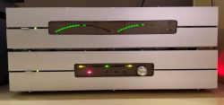
The uC was the easiest to use electrically, and the module was supposed to match the aesthetic concept (preamplifier visible underneath, second power amplifier and tuner). Swing-out with such a large rectangular... [Read more]
It was a joke with the tilting one - of course they wouldn't fit in the housing. However, I would make flat rulers, not arched and one under the other or divergent, and windows in housings of the... [Read more]
Doing something like this in analog is a complete misunderstanding, not these times. Why complicate the design, increase the cost, limit the possibility of modifications? [Read more]
And I completely do not understand placing such trinkets in such a form in an amplifier. If it was calibrated and indicated the power output, I would understand. But without that, what's it for? Just... [Read more]
Whatever, whatever. You can scale (there are PRs), scale can also be applied, but why? It is supposed to blink, just like the VU-meter on the 2*20 LCD described on Elektroda or the Chinese rulers. The... [Read more]
For it to make sense. I don't like pointless trinkets in the equipment, for me it's just "wiocha". Personally, I'd prefer a plain/bare front-panel to such flashing trinkets, Just just for... [Read more]
If anyone likes looks... :lol: [Read more]
With all due respect, you're the lover of appearances here. You named your creation "Vehicle Indicator" (for the amplifier). And what is the boost indicator??? For it to be called a VU indicator,... [Read more]
To be exact, from SJP: meter: an instrument used to measure (e.g. voltage) indicator: a measuring instrument that indicates the state of something e.g. voltage indicator: an instrument for detecting... [Read more]
I don't confuse concepts. I know what a gauge is and what an indicator is. It is generally accepted that we expect the indicator to indicate the presence of something (some signal, switching on something),... [Read more]
E.g. fuel gauge. Instead of white graduation lines, I have gaps between the diodes :) https://obrazki.elektroda.pl/6099619600_1676035640_thumb.jpg There is indicative information about the value... [Read more]
Well, no. In their constructions, people can connect similar diode lines in different ways; e.g: - at the preamplifier input, right after the input selector (because they shine so much better); - on... [Read more]
Buddy Tytka, you're right, maybe I really took a big shortcut. Connection in the only correct way in my opinion (I don't use the tone control for the power amp), and the fact that the end of the... [Read more]
In general, when it comes to appearance, it's quite good, although there is no scale, although now thumbnails are in fashion ;) However, personally, I am not in favor of using processors where there... [Read more]