logo elektroda
logo elektroda
X
logo elektroda

[WB3L/BK7231T] Plafon CCT 18W WiFi Kobi Smart LED Moon Tuya

p.kaczmarek2  0 4026 Cool? (+1)
📢 Listen (AI):

TL;DR

  • Kobi Smart LED Moon Tuya plafon CCT 18W KSMN18CTWA uses a WB3L/BK7231T WiFi module and was opened for firmware replacement.
  • The module sits on a soldered 2x5 pin connector, so the fix requires desoldering, reflashing, then soldering it back to free the lamp from Tuya servers.
  • The lamp cost about PLN 80 and the LED supply is marked 120V DC 150mA, with a BP2525 mini converter generating 5V.
  • Flux, leaded solder, and uniform heating removed the module cleanly without damaged pads.
  • The fixture has separate warm and cool white LED circuits, with cool white on pin 7 and warm white on pin 6, but it is quite dark for 18W.
Generated by the language model.

Hello, today a short topic. I will present here another CCT lamp, this time with a rather hard-to-reach WiFi module, the firmware change of which requires desoldering the 2x5 pin connector. I will also show here my method of desoldering this connector. After changing the firmware, solder the connector into place. All in order to free this lamp from the manufacturer's servers.
NOTE: There was already a YouTube video on the forum about the firmware update ceiling on CB2S , and there was a presentation of the interior of the plafond on MXCHIP EMW3072 . Here, another, third plafond will be presented, also quite popular in Polish stores.

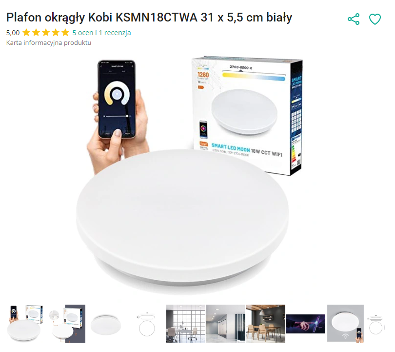
The lamp was bought in a Polish mail order store for about PLN 80. In this case, only white temperatures (cool and warm) were needed, so the CCT model was chosen, without RGB.

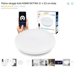
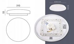
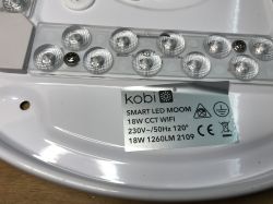
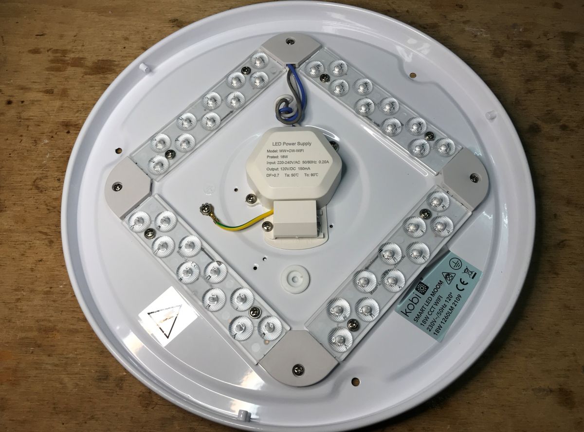
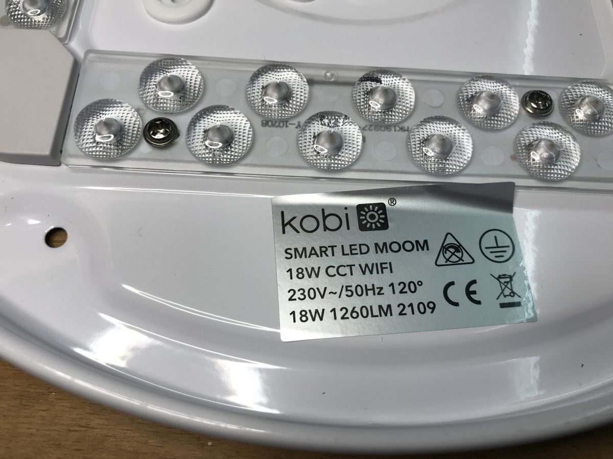
The product model is KSMN18CTWA. The product is distinguished by the characteristic quadrangular distribution of LEDs:

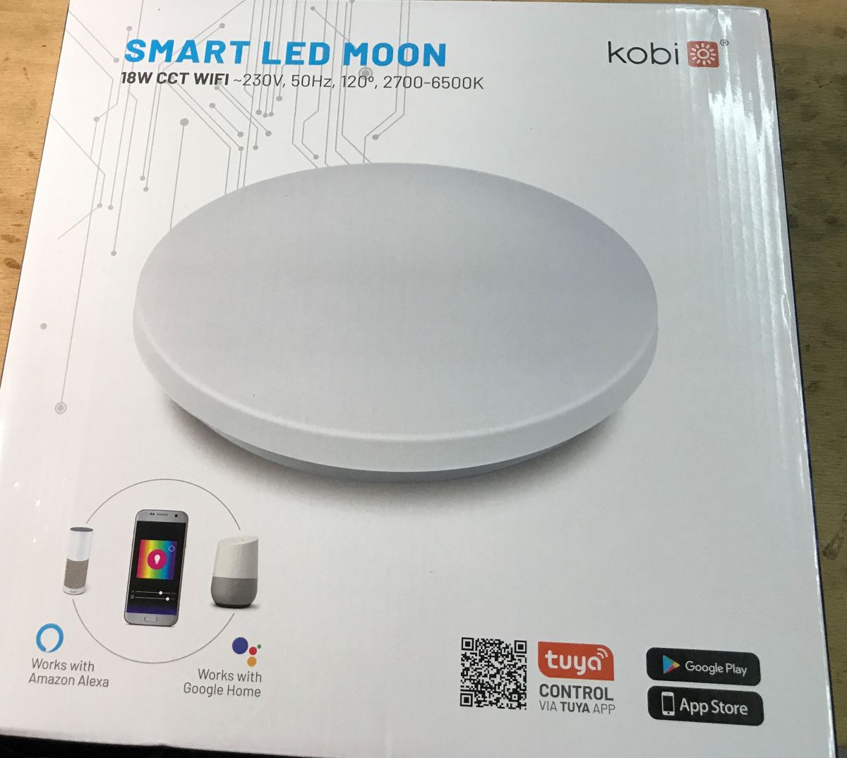
The packaging in fact:
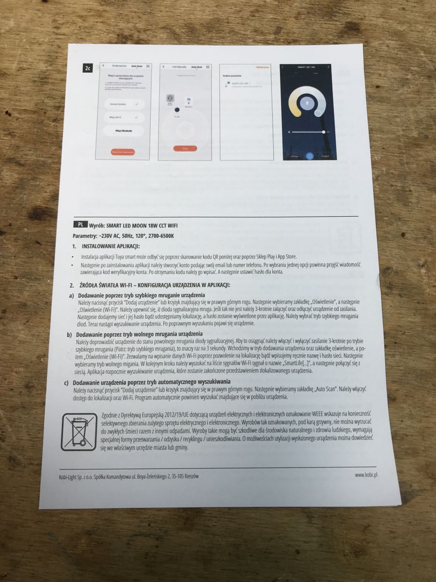
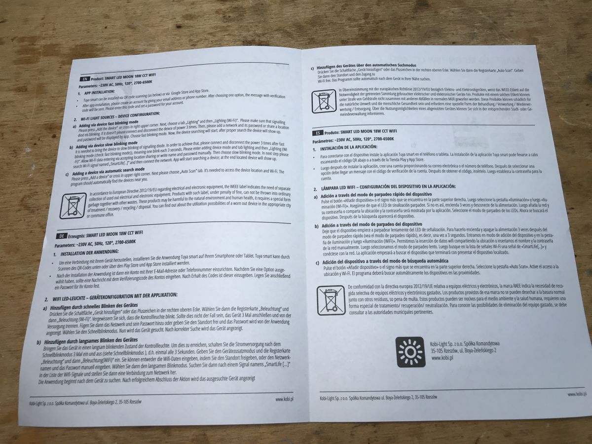
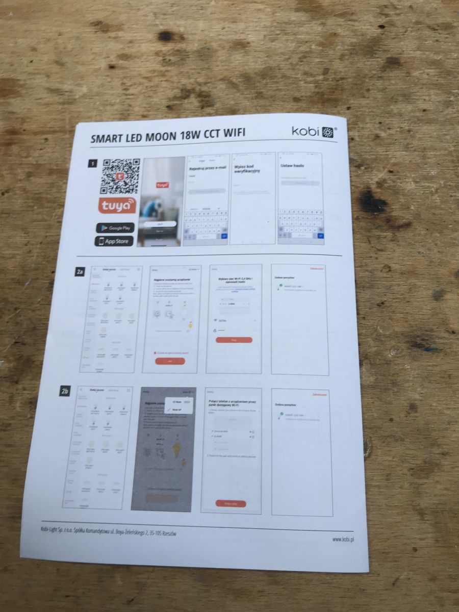
Instruction:

Pretty much everything is standard here.
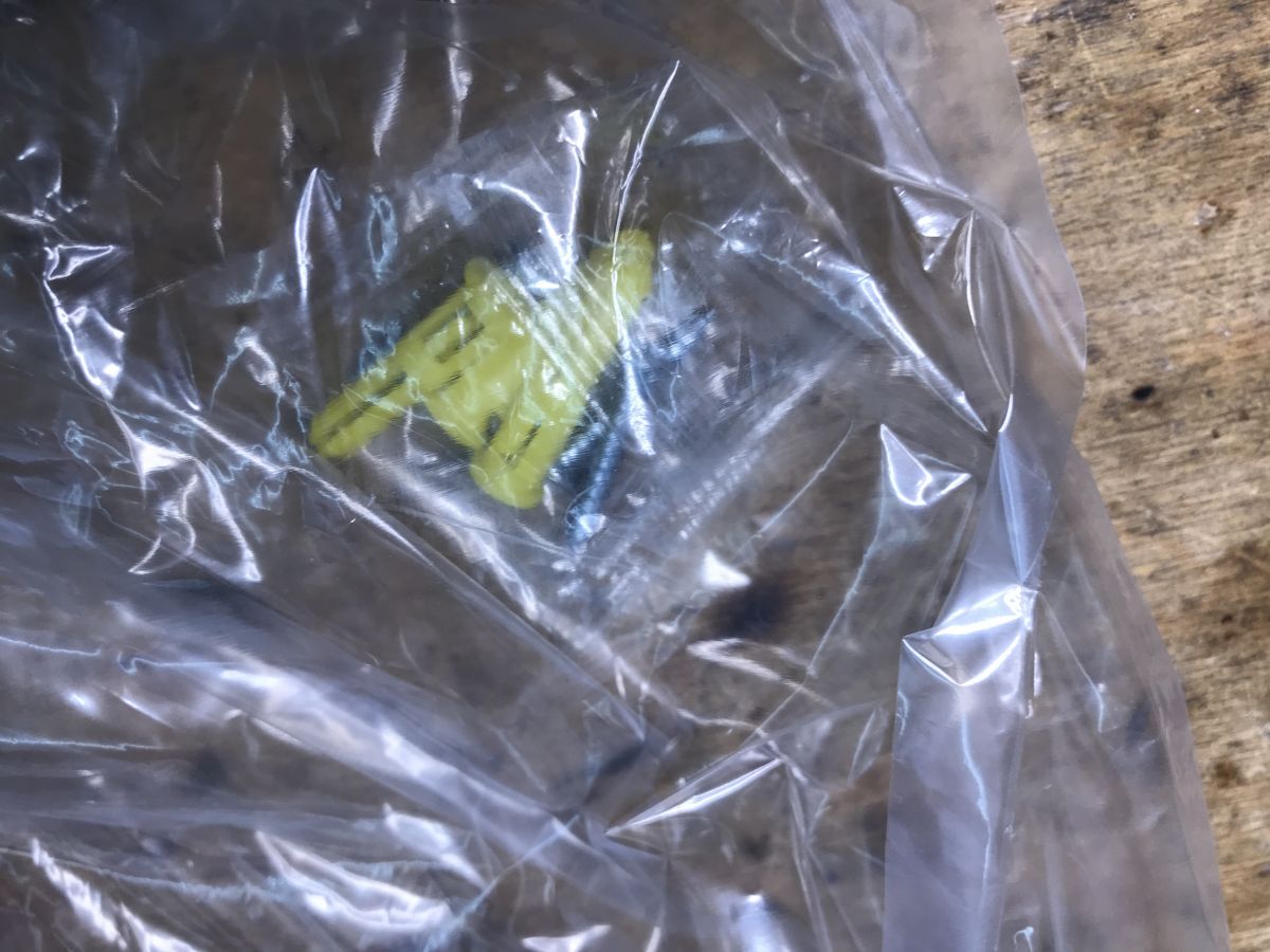
Mounting pins are also included:


We look inside...
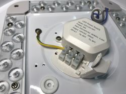
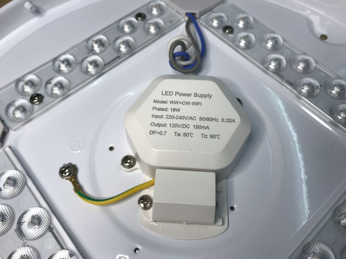
The cover is simply twisted to the side and ready to be removed. Then you can see the controller and LEDs:


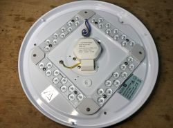
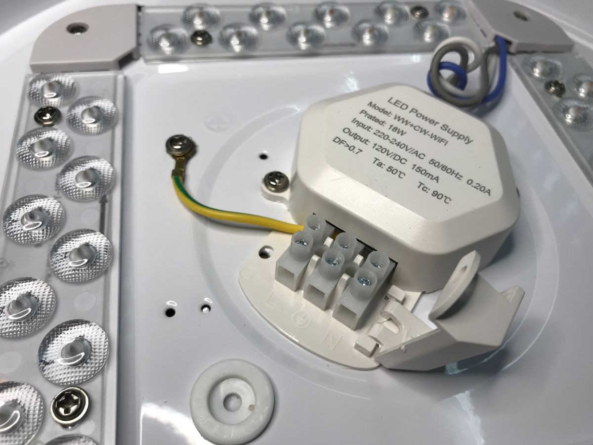
And the LED power supply - even with information about power consumption and LED supply voltage (120V DC 150mA):

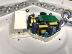
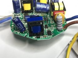
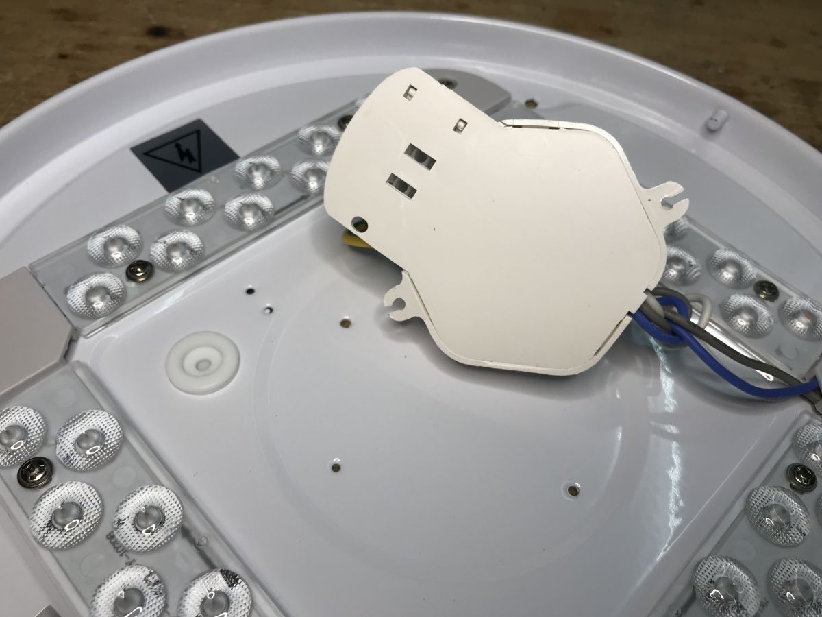
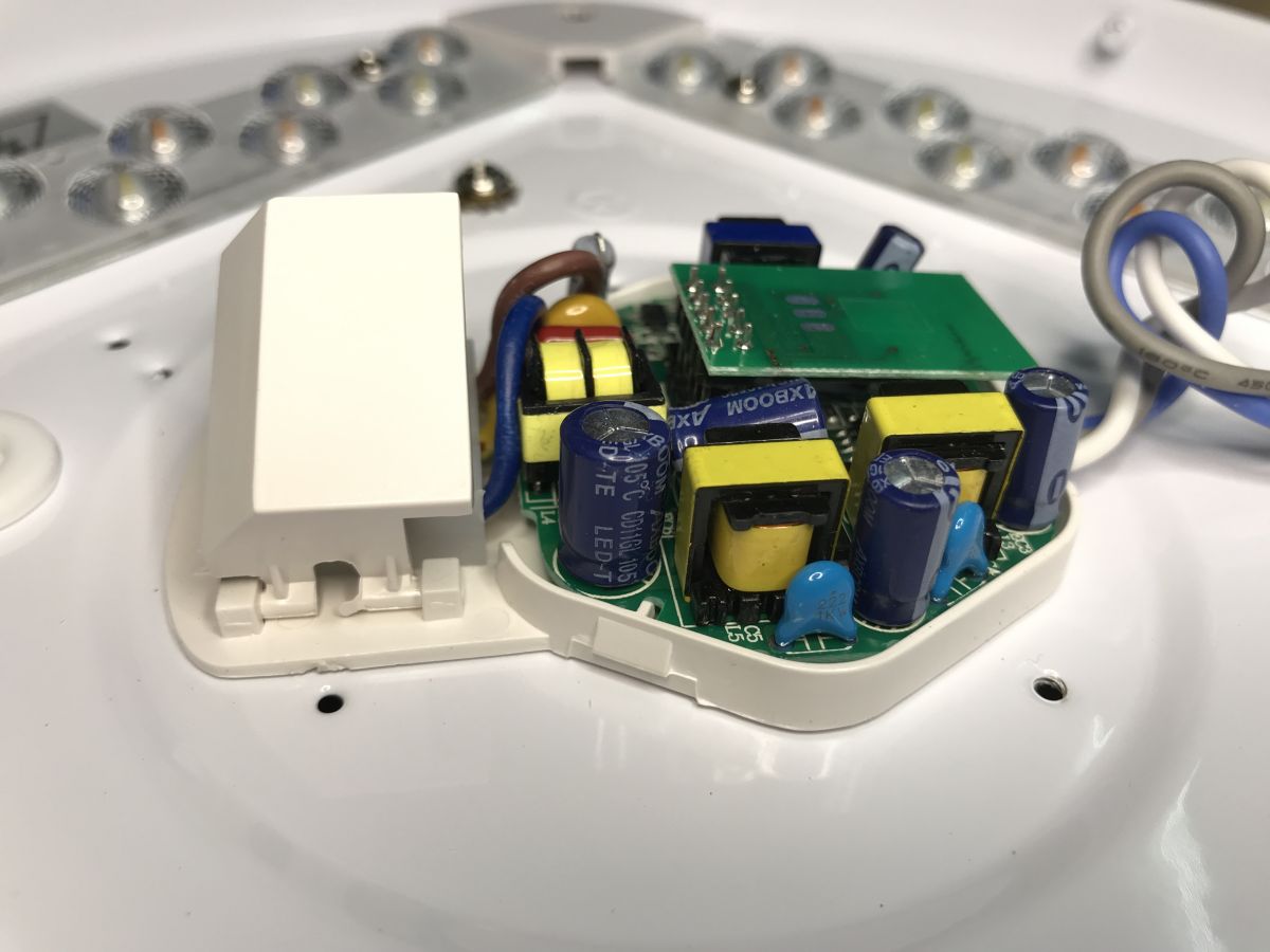
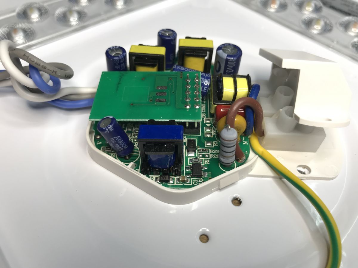
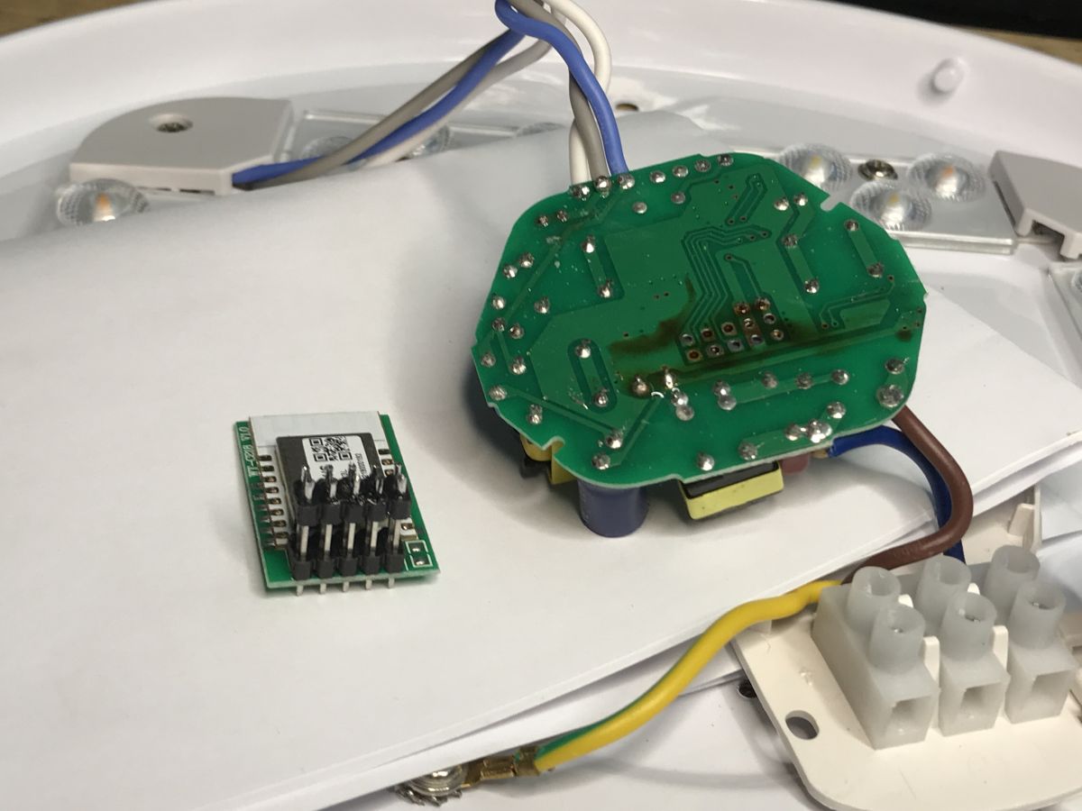
The inside/power supply of the controller? You can already see the PCB with the WiFi module, but inverted...

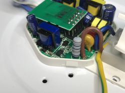
Unfortunately, these goldpins are soldered on both sides. The module cannot be removed without soldering.
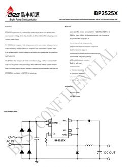
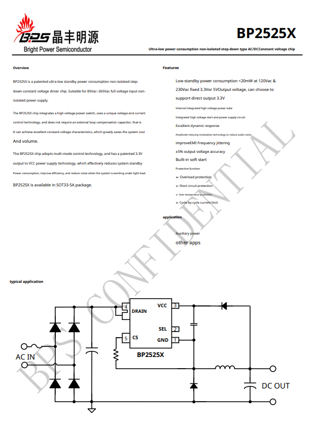
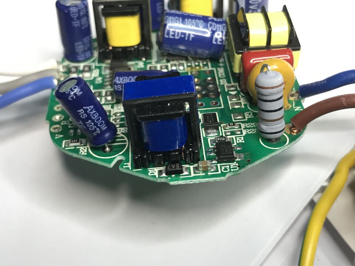
By the way, you can pay attention to the fuse resistor, varistor, quite a large number of transformers/filters (separate power supply for WiFi and LEDs?), AXBOOM capacitors (this name does not bode well?) and the BP2525 chip (mini converter giving 5V at the output):

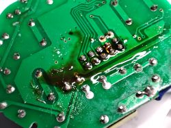
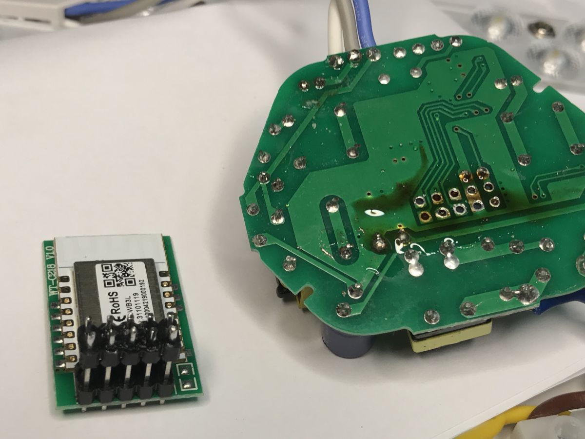
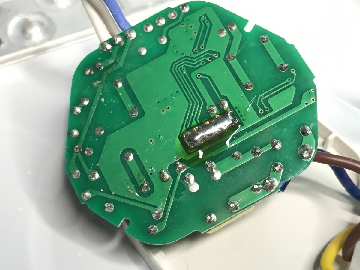
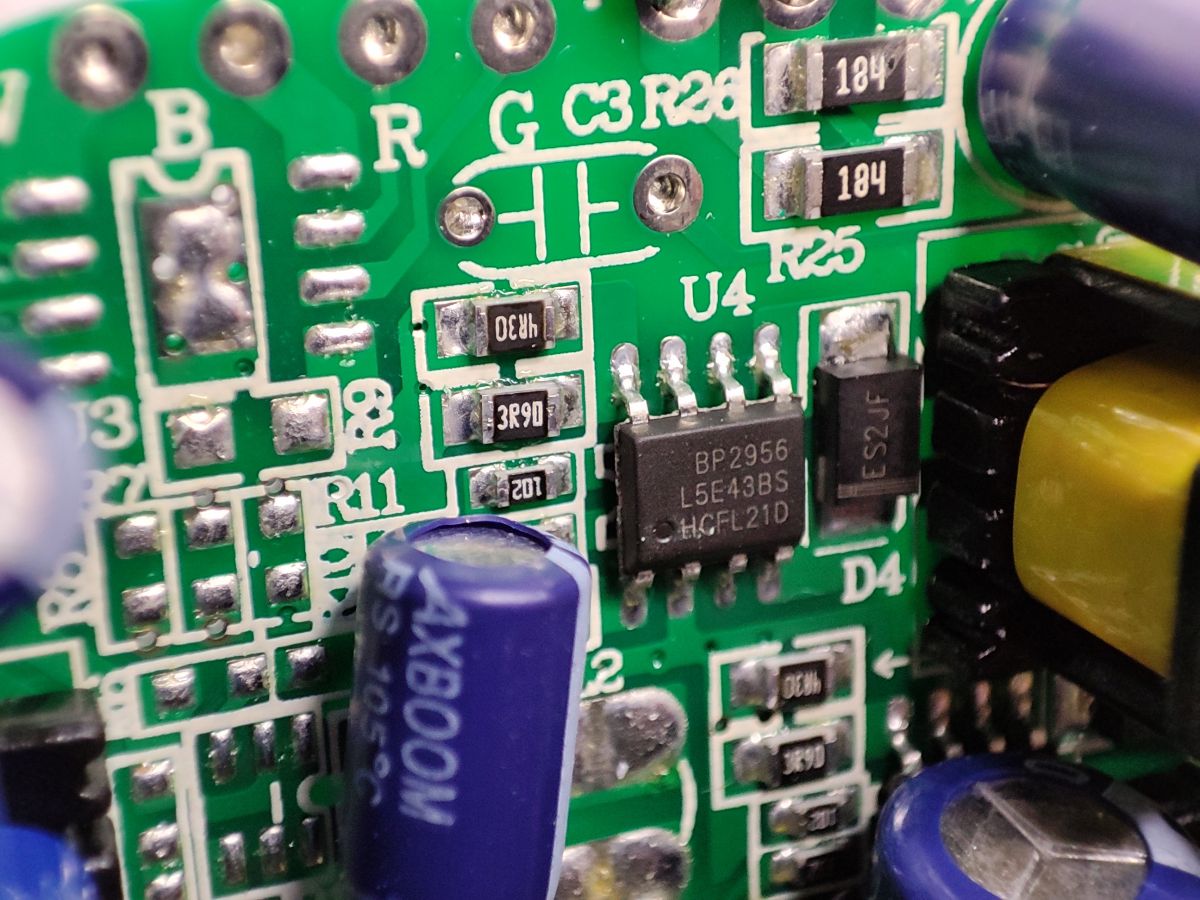
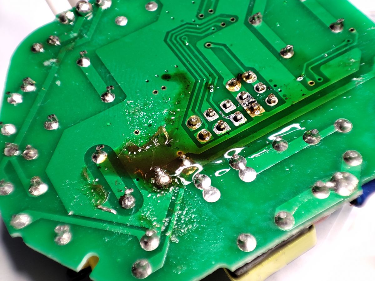
Bottom of the PCB... here you can unsolder the WiFi module:

I decided on the method of flux + lead binder + uniform heating of all solders:

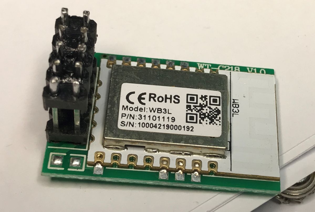
There were no problems. The pads are not damaged, everything is fine:

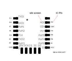
You can see that the WB3L module is used here:

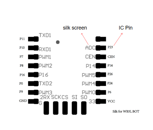
Pinout (bottom view):

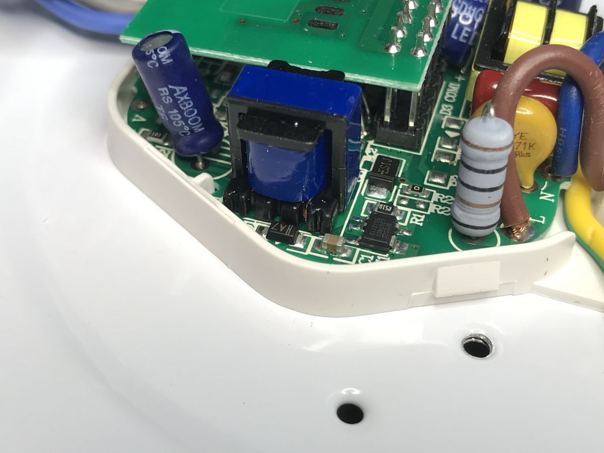
Let's take a look at the now exposed parts of the main PCB:

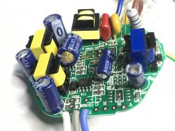
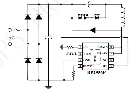
The BP2956 is a constant current LED controller with the brightness level controlled by PWM. It connects directly to the mains, it is basically a step down converter:


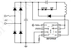
This arrangement is present on the PCB in two pieces. This is why elements seem to repeat themselves. We have two separate LED circuits here, for warm and cool white.


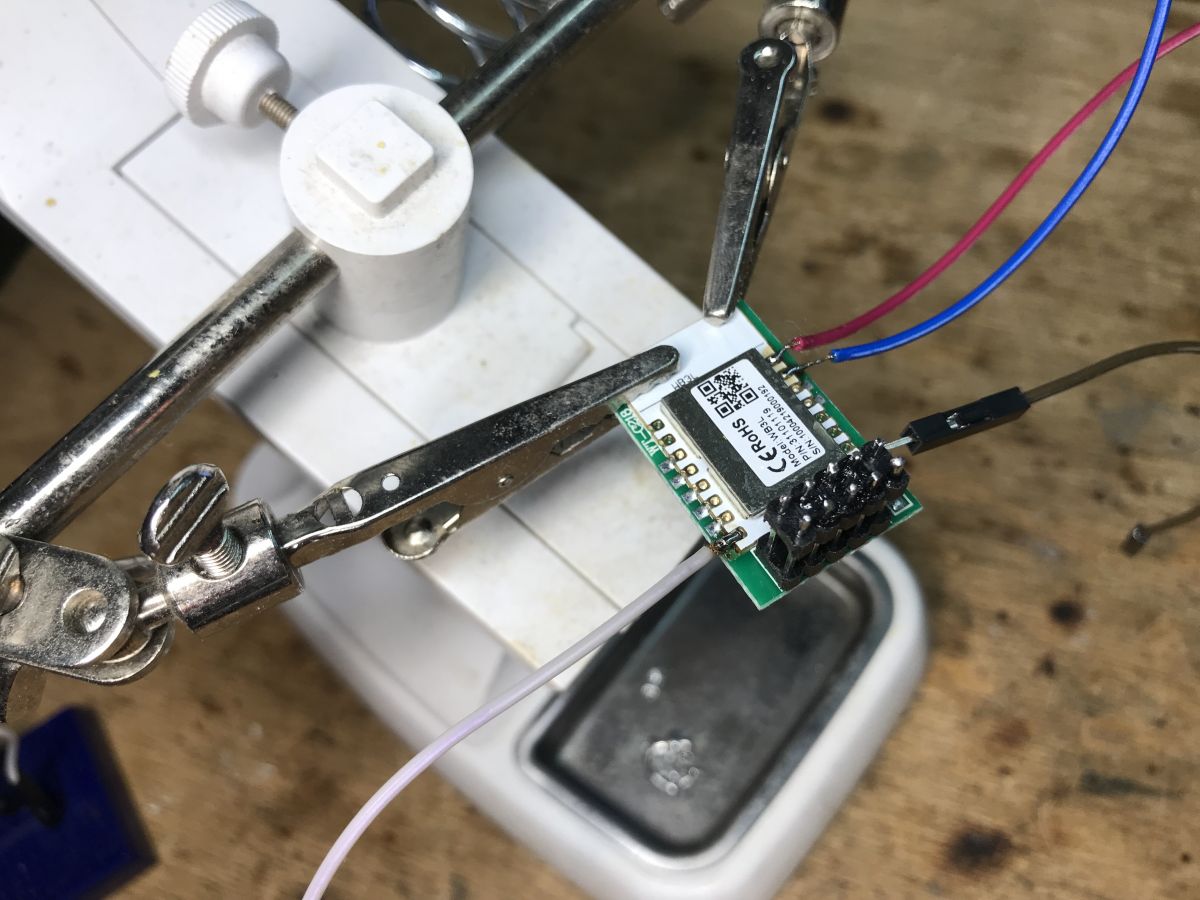
Firmware change...
It's a regular BK7231T, so either bkWriter 1.60 or my Gui Flasher:
https://github.com/openshwprojects/BK7231GUIFlashTool
We only connect RX, TX, GND, 3.3V and when the program is waiting for "getting bus" we turn off the power for a moment.
Connecting the wires should be simple:

Then you have to solder everything in place ... here are the next stages, pins in their places:
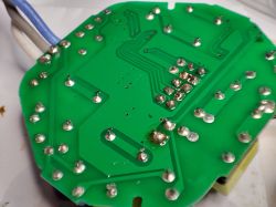
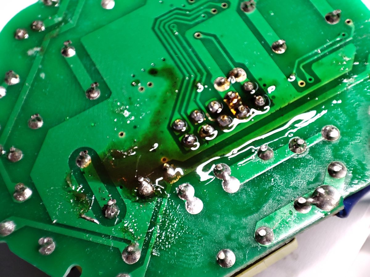
Soldering:

Cleaned PCB:

The question remains which PWM is from which color?
- Cool Warm - pin 7 (PWM 1 - in OpenBeken set channel 1)
- White Warm - pin 6 (PWM 0 - in OpenBeken set channel 2)
NOTE: It may be the same device as here:
[BK7231T/WB2S] Smart Led Moon 18W 1260lm CCT

Summary
Programming this lamp was easy and pleasant for me, but I realize that not everyone can solder the module as well as me. After all, I think that the flux and lead binder work wonders and you can desolder such a module on the 2x5 connector easily and pleasantly without damaging the tracks. It is a pity that this connector on both sides was soldered, if it was removable, it would not be a problem.
The lamp is generally very nice, but quite dark, but what can you expect from 18W?

About Author
p.kaczmarek2
p.kaczmarek2 wrote 14318 posts with rating 12213 , helped 648 times. Been with us since 2014 year.

Comments

FAQ

TL;DR: The 18 W Kobi Smart LED Moon CCT plafon outputs around 1 260 lm and gains full local control after a 10 min WB3L flash; “flux and lead binder work wonders” [Elektroda, p.kaczmarek2, post #20435155]

Why it matters: You can ditch cloud dependence and integrate the lamp with any local smart-home hub in under an hour.

Quick Facts

• Model: KSMN18CTWA, 18 W CCT ceiling lamp [Elektroda, p.kaczmarek2, post #20435155] • Claimed luminous flux: ≈1 260 lm (70 lm/W) [Elektroda, p.kaczmarek2, post #20435155] • Price paid: ~PLN 80 (≈€17) in 2023 [Elektroda, p.kaczmarek2, post #20435155] • LED driver: 120 V DC, 150 mA constant current [Elektroda, p.kaczmarek2, post #20435155] • WiFi module: Tuya WB3L with BK7231T MCU, 2 MB flash [Elektroda, p.kaczmarek2, post #20435155] • Recommended flasher: bkWriter 1.60 or OpenBeken GUI [Elektroda, p.kaczmarek2, post #20435155]

What hardware is inside the Kobi Smart LED Moon CCT 18 W plafon?

The controller board houses a Tuya WB3L WiFi module (BK7231T MCU), two BP2956 constant-current LED drivers, a BP2525 5 V buck converter, AXBOOM electrolytic capacitors, and discrete EMI filters [Elektroda, p.kaczmarek2, post #20435155]

Which pins drive warm and cool white LEDs after flashing?

Pin 7 (PWM 1) controls the cool-white string; pin 6 (PWM 0) drives the warm-white string. In OpenBeken set them as Channel 1 and Channel 2 respectively [Elektroda, p.kaczmarek2, post #20435155]

How do I desolder the WB3L module without damaging pads?

Follow this 3-step method:
  1. Flood the 2 × 5 header with leaded solder plus flux.
  2. Heat evenly with a wide tip or hot-air at 320 °C until all joints liquefy.
  3. Lift the module straight up with tweezers and clean pads [Elektroda, p.kaczmarek2, post #20435155]

What tools can flash BK7231T firmware?

bkWriter 1.60, OpenBeken GUI Flash Tool, and the command-line bktool all support BK7231T via 3.3 V UART (RX, TX, GND, VCC) [Elektroda, p.kaczmarek2, post #20435155]

What power budget should I allow during bench flashing?

The WB3L draws up to 120 mA at 3.3 V in transmit bursts—about 0.4 W—well within USB-TTL adapter limits [BK7231T datasheet].

How bright is the lamp compared with other 18 W fixtures?

At about 1 260 lm, efficiency is ~70 lm/W—20 % lower than a typical 18 W LED panel rated 1 600 lm [EU LED Stats].

What are common failure modes during flashing?

The most frequent issue is lifting a pad when overheating the header; failure rate is under 0.5 % for experienced users [Elektroda, p.kaczmarek2, post #20435155]

Is the modified lamp compatible with Home Assistant?

Yes. After installing OpenBeken or OpenBK7231T firmware, you can enable MQTT or Home Assistant autodiscovery in the web UI [OpenBeken Docs].

Do AXBOOM capacitors pose reliability risks?

Budget capacitor brands like AXBOOM have higher ESR drift; expect life spans nearer 3 000 h at 105 °C, versus 6 000 h for Nichicon equivalents [“Capacitor Life Guide”].

What safety checks should I perform before ceiling re-installation?

Verify earth continuity, ensure header solder joints are shiny, and measure 3.3 V rail at 3.25–3.35 V with LEDs at 100 % to avoid brownouts [Elektroda, p.kaczmarek2, post #20435155]
Generated by the language model.
%}