Audio spectrum display (ESP32, WS2812B)
TL;DR
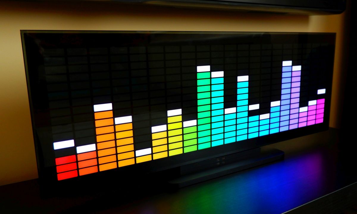
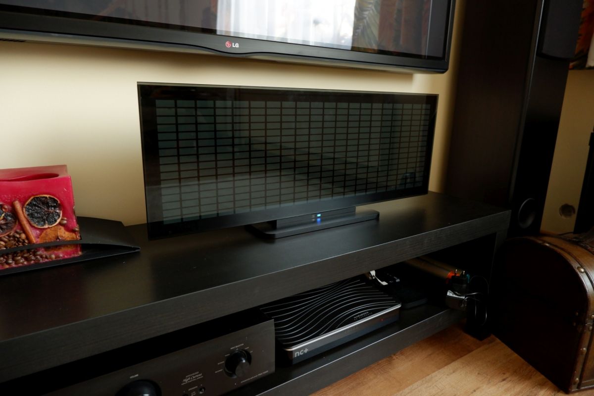
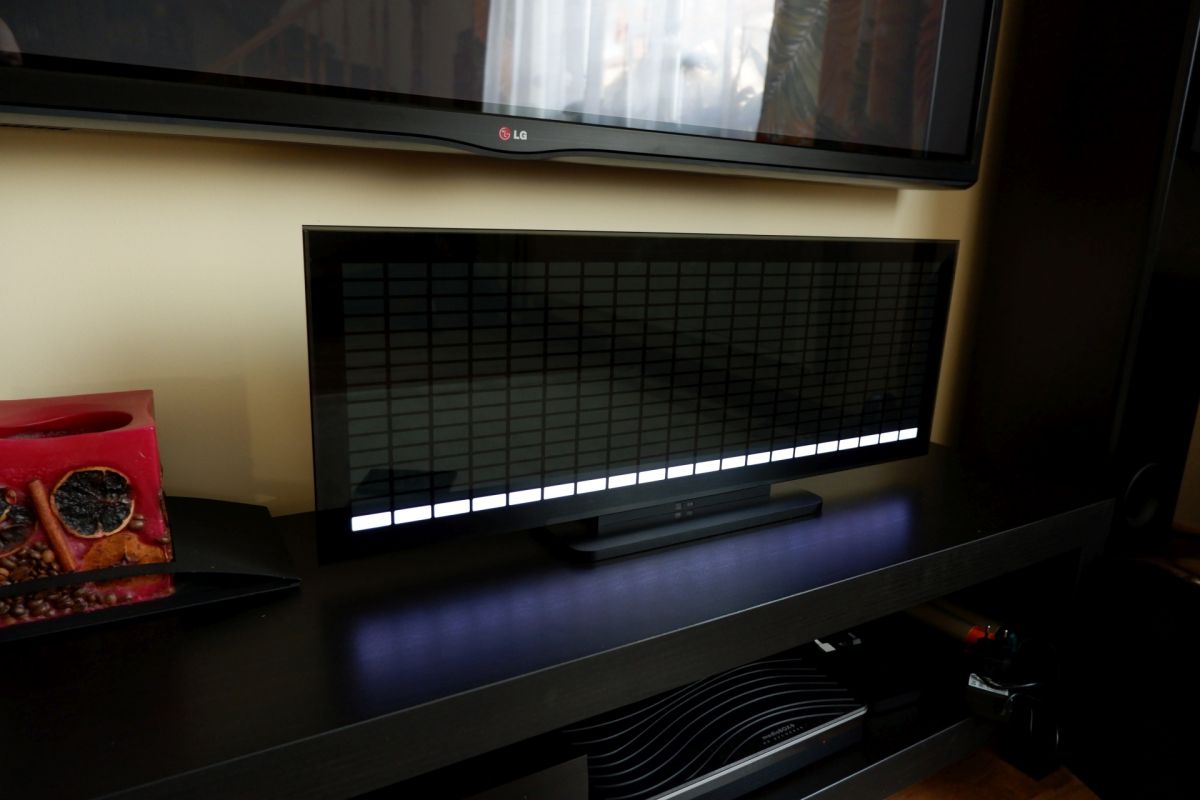
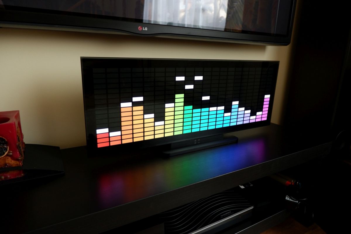
- A 20-bar, 16-point audio spectrum display uses an ESP32 and a 640-LED WS2812B strip for a larger, classic-style illuminated panel.
- The display runs FFT code from ESP32_FFT_VU, with ADC sampling moved to a timer interrupt and automatic level control added for varying music levels.
- An IR remote with an Atmega8/Atmega88 receiver handles power, brightness, effects, and peak toggling, while standby keeps only the receiver active.
- The build uses 320 light points from two LEDs per pixel and measures 710 x 256 x 28 mm, or 710 x 280 mm with the base.
- It reaches about 20 FPS on a 16x40 LED matrix and 29 FPS on an 8x8 matrix, but the code needs ESP32 Arduino 1.0.4.
AI summary based on the discussion. May contain errors.
Hello everyone :)
In particular, lovers of lights, illuminophonics, etc.
The presented device displays the acoustic spectrum in the form of 20 bars, 16 points each. It's hard to call them a spectrum analyzer. I associate the analyzer more with a measuring device, although the frequency display is quite accurate here, which cannot be said about the level scaling, which changes anyway. But more on that below.
Similar structures can be found on the Internet. However, most of them are unfinished in my opinion. Flashing LED strips glued to "something". And so the idea was born to build a nicer display referring in style to classic factory constructions, but in enlarged dimensions.
The matrix is made of a 640 LED WS2812B strip. Due to the size of a single "pixel" 30 x 11mm, it is backlit with two diodes, which gives 320 light points.
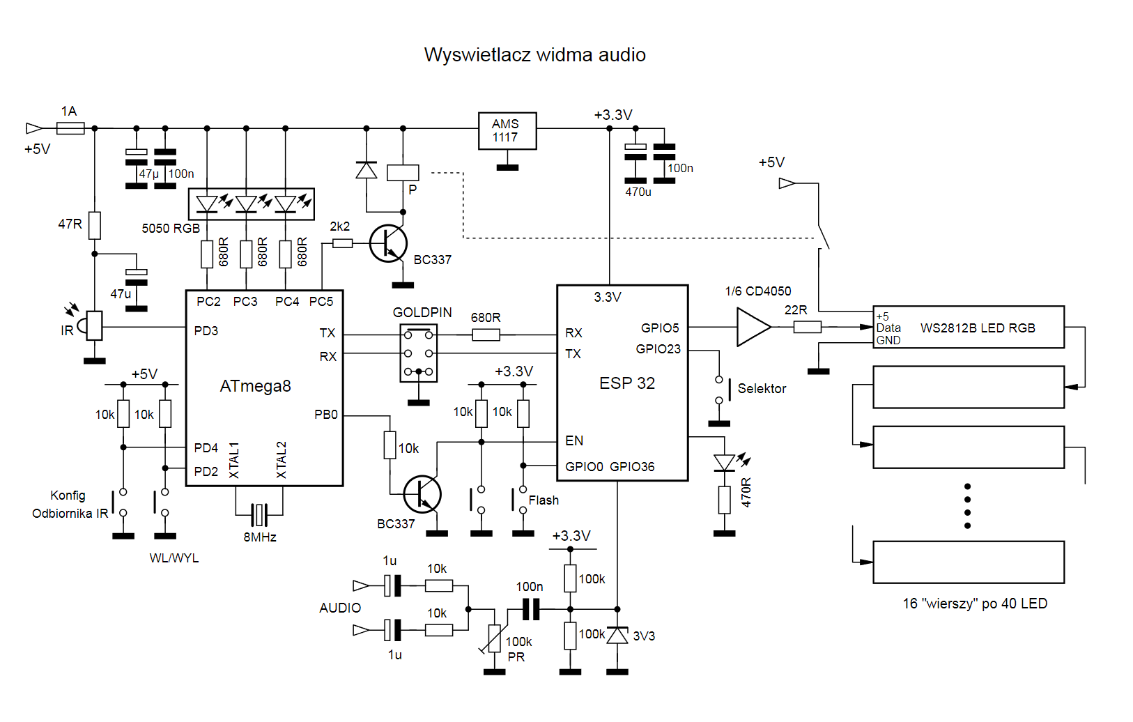
The heart of the control system is the ESP32. This is actually my first project on this MCU and I'm just getting to know it. As for the program code, there are a lot of ready-made sources for building similar devices. I decided that there is no point in breaking open the door and I chose a ready-made one. https://github.com/s-marley/ESP32_FFT_VU
Unfortunately, the code only works with version 1.0.4 of the ESP32 Arduino board. With higher versions there are problems with ADC sampling above 20 kHz.
However, I made some modifications and fixes:
- Changed ADC sampling from blocking loop to timer interrupt, which significantly accelerated program execution.
As of today, I got about 20 FPS refreshing the matrix with the size of 16x40 LED and 29 FPS with the 8x8 matrix, and probably not more
you have to, because the pillars will become "nervous".
- Automatic audio level setting, but on the side of the FFT band values. Something like "ARW". The sound level differences between different music albums are significant and the sound input level had to be adjusted. The aforementioned "ARW" handles it quite well.
The device is operated with an IR remote control. The learning IR receiver is based on Atmega8 or Atmega88. It is able to handle the most popular formats of remote control commands (Nec, Nec16, Nec42, Samsung32, sony(SIRCS) Denon, Sharp).
There are 6 commands to use.
1 - Switching on and off
2 - Panel brightness +
3 - Panel Brightness -
4 - effects switching +
5 - effects switching -
6 - enabling or disabling "peaks"
Only the IR receiver module is active during standby. After receiving the command to turn on the device from the remote control, the ATmega unlocks the ESP32 and turns on the power to the LED strip.
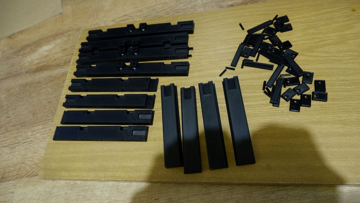
Construction :
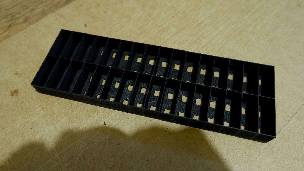
Almost the entire structure is printed on a budget home printer from PLA, with a filling of 20%, in places densified to 90% for screws. The exception is the rear wall (HDF 3mm) and base (MDF 10mm).
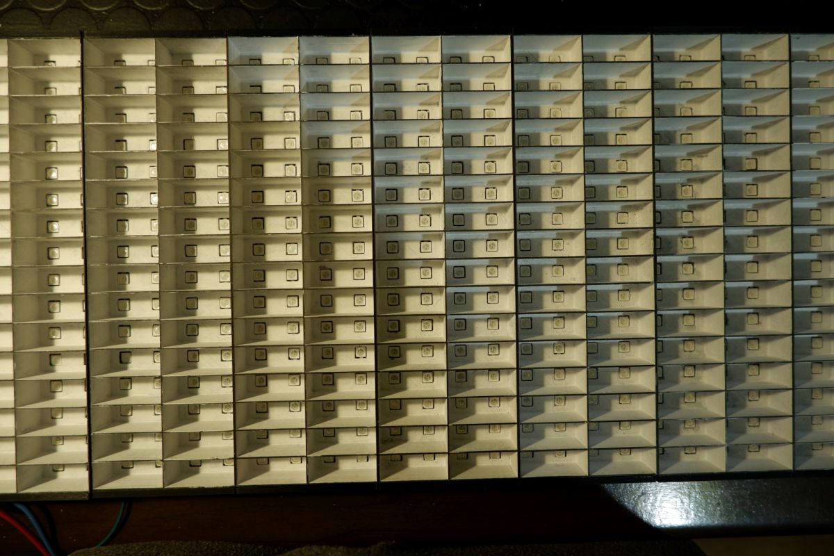
LED compartments.
They need to be painted white on the inside to diffuse the light better.
Trial assembly of partitions and masking
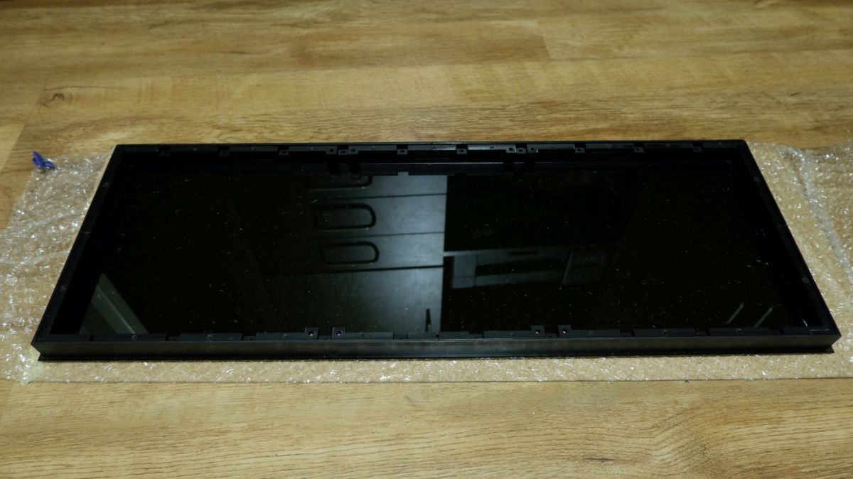
Due to the limited size of the print, the casing frame is printed in pieces and then glued together.
Installation:
Housing frame glued to tinted glass.
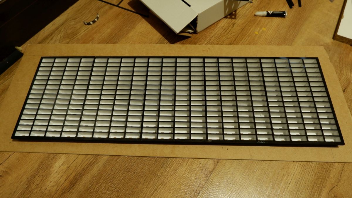
Now the grille
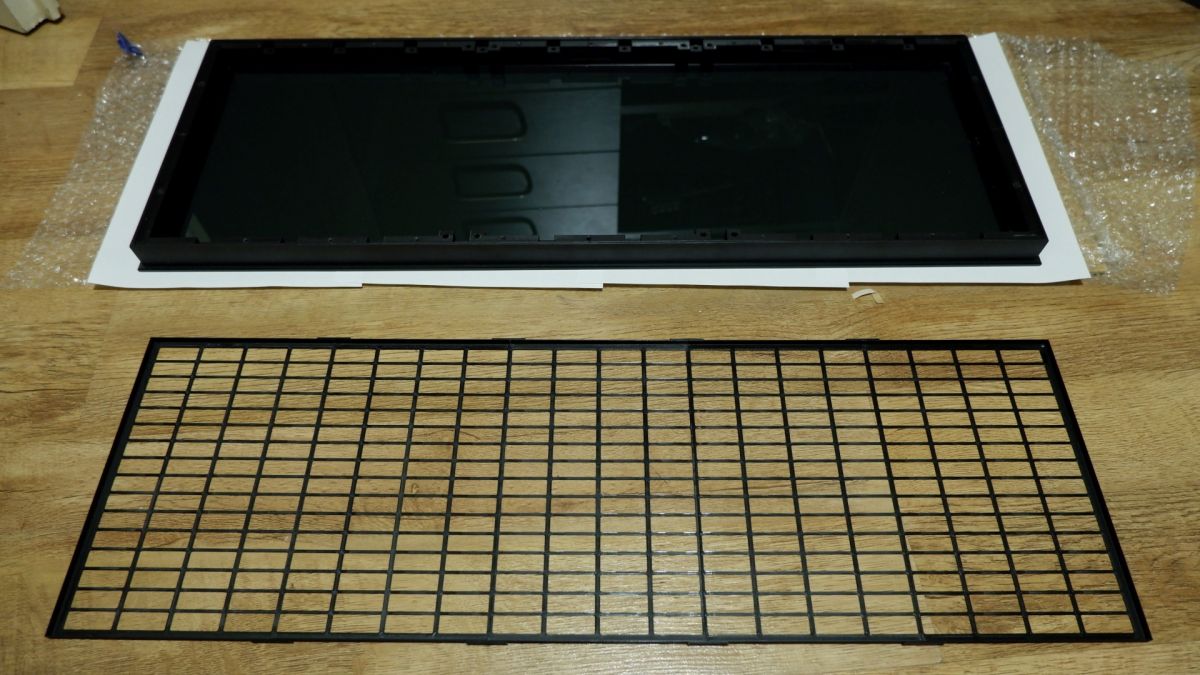
On the grille there are screens made of white PVC 160um. Obtained from the covers of office folders. So in pieces...

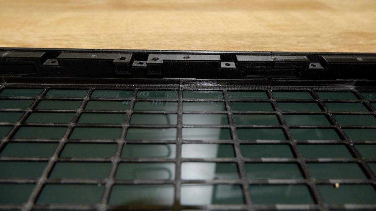
It's time for partitions with glued and soldered LED strips. The partitions are not glued together to better adhere to the grille and the glass.
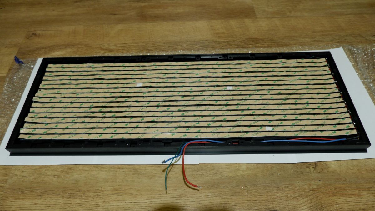
Installation of elements pressing the partitions to the glass with the mask. These elements also center the partitions vertically.
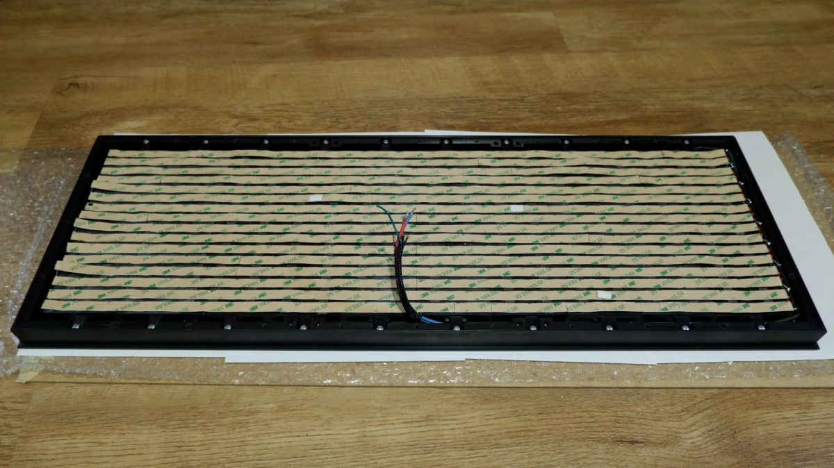
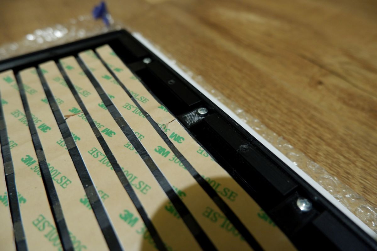
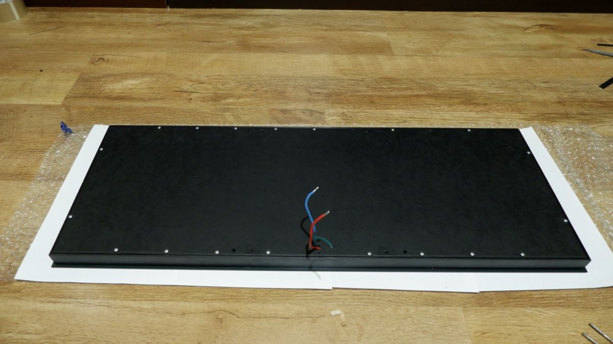
The whole is closed with an HDF board with screws.
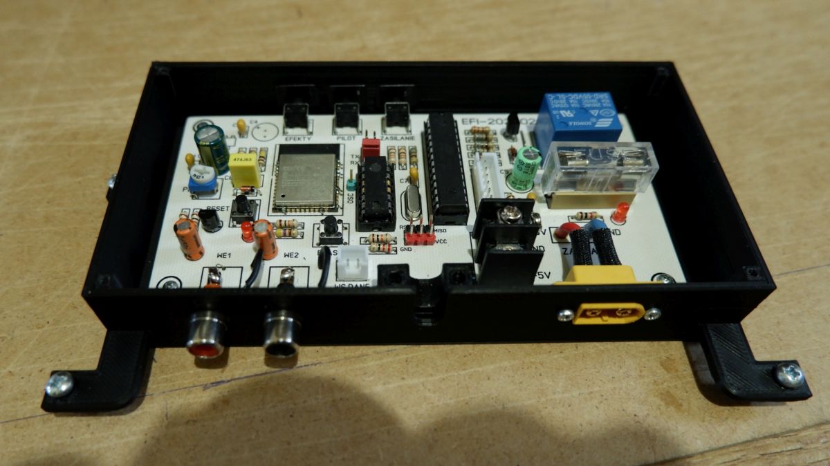
Installation of vertical supports with base and electronics housing
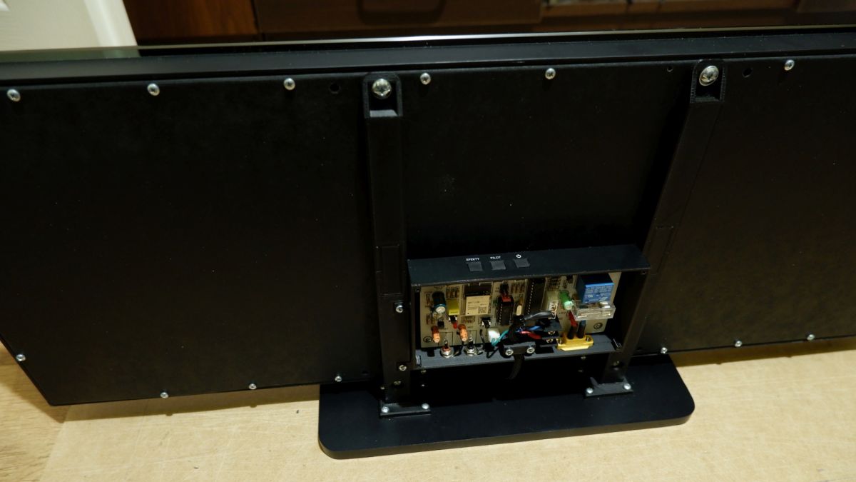
Destination
Another electronic board
The whole is powered by a 5V 22A power supply.
Panel dimensions 710 x 256 x 28 mm.
Dimensions with base 710 x 280 mm.
Source codes - Arduino IDE.
Diagram. I hope there are no errors on it..
A short action video. It still doesn't show the live effect.
https://youtu.be/aGNrLPwe1e0
Sorry for the quality of the photos. These blacks are hard to photograph...
I am attaching the ESP32 source codes. Prototype code. it will probably be modified. And the source of the IR receiver
And that's all in a nutshell...

efi222 wrote 779 posts with
rating 1219 , helped 12 times.
Live in city Toruń.
Been with us since 2019 year.
Comments
The workmanship is very nice, but in my opinion it lacks fluidity - maybe it's worth dividing the 640 LED chain into smaller sections and connecting it to several ESP lines, which should ensure faster... [Read more]
For 600 LEDs you can theoretically achieve 55 FPS in a chain, so there should be no problems. Very aesthetically made design. The end result is really nice. [Read more]
Theoretically... practically the CPU has other things to do in the meantime. Also "theoretically" ESP32 has 2 cores, so you can delegate one to send data to the LEDs, the other to the rest. It should be... [Read more]
There can be no talk of advanced programming as I am an amateur with no professional involvement in electronics, let alone programming, which I have been learning for probably 5 years. I build these devices... [Read more]
5 years is quite a lot ;) Maybe it's a good time to take care of a more developmental environment than arduino ide and assembling everything from ready-made blocks? [Read more]
There used to be a campaign against Bascom... Now Arduino is falling out of favor.. Besides, my friend at my age, I'm not likely to look for a more developmental environment. I don't think I even... [Read more]
And she was very right - I wasted 20 years of my life on this damn thing. For the same reason as bascom, it is justified. And that's praiseworthy :) I was referring more to software "blocks". ... [Read more]
It looks great. I like it in almost every way. He can possibly try to use these colors more creatively, we have such a wide range and basically it's just either falling white blocks or the color of... [Read more]
I also started with Bascom... And now? Well... Half the world of amateur builders writes in the Arduino IDE. They share their scribbles with the rest of the world. I think that's good. It encourages... [Read more]
Virtually every manufacturer of microcontrollers offers a free environment for them. Is the arduino good - for starters, the problem is that people get stuck in this invention for many years because they... [Read more]
Very nice workmanship, show the 20Hz-20kHz sweep, it will be possible to assess the real usefulness. [Read more]
Very nice workmanship, all materials available and the display can be repeated by an intermediate hobbyist. And this is the purpose and principle of publication in the DIY section. However, the discussion... [Read more]
Exactly, pointless discussion here, maybe a moderator will cut it to a new thread? And for the display praise and plus, nice workmanship and some electronics also had to be handled. [Read more]
And that's how it should be, the most important thing is satisfaction with what you've done, and what's more, you did it yourself, being an amateur. There are a lot of people on the forum... [Read more]
Thank you friends for the kind words :) I've been building it since last fall. Lots of different problems and tests. Test prints, screen selection, distance from the screen and more... At the... [Read more]
You see! And I like it, it is not only a trinket but also a useful device. [Read more]
I've done this kind of research before. That's why in the description it says that the frequencies are ok. It's just difficult to determine the sound level that "ARW" changes, making sure that... [Read more]
What is your scaling of the bar relative to the signal? looks linear and should be logarithmic, then ARW would be unnecessary. [Read more]
The scaling of the bars is linear. I was supposed to get around to it sometime and see it with a logarithmic scale. The code still needs polishing. [Read more]