logo elektroda
logo elektroda
X
logo elektroda
ADVERTISEMENT
Treść została przetłumaczona polish » english Zobacz oryginalną wersję tematu
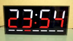
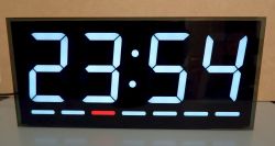
  • Digital clock with an LED display showing the time 23:54.

    Hello :)
    Watches featuring WS2812B have already been published on Elektroda. I would like to present my version. I had some of this tape left over from recent projects and decided to use it. Access to a 3D printer may make this project difficult.

    The clock has digits that are 79 mm high. It`s big, but you get used to it. After several experiments, it seems that this height is optimal when using the most popular strip with a density of 60 LED/m. In addition to the dots, there are two diodes (on the tape) per digit segment. I also tested with smaller displays. The minimum height is 45mm (one diode per segment, without removing the LED from the strip).

    The clock shows the days of the week in addition to the time. A friend of mine talked me into it and I think it was a good idea. The day display can be placed above or below the numbers. The current time is downloaded from NTP servers every hour by default. Undoubtedly, the advantage of this design is the almost unlimited display in terms of colors and animations. You can also link the display to the calendar and display different patterns on specific dates.

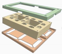
    All elements except the back wall (HDF) are printed from PLA. The mounting frame is glued from two parts.
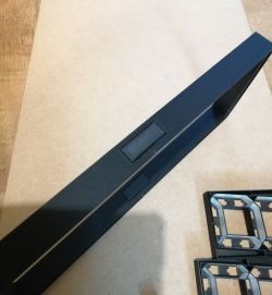
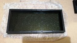
    Black mounting frame for a clock, assembled for installation.

    And as a finishing touch, a furniture edge is pressed onto it.
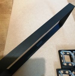
    Clock frame with LED display and digit segments.

    I glued the partition-type elements from the inside with white self-adhesive foil. In my opinion it goes faster than painting white. And the job is clean.
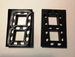
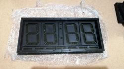
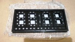
    Two black plastic frames for LED clock digits.

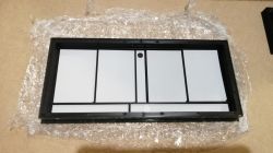
    After unsuccessfully searching for white PVC for matte screens, I experimented with a white print. I think it looks quite nice. Up close you can barely see the print threads, but from a distance of several dozen centimeters you have to look closely to see them. And if someone doesn`t know about their existence, they don`t notice them :)
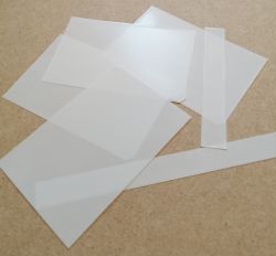
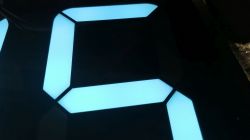
    White sheets printed on a 3D printer lying on a brown background.
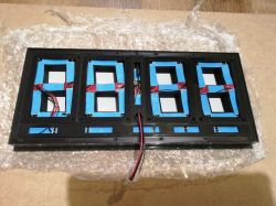
    Close-up of an LED display segment with blue LEDs.

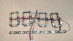
    connected sections of tape

    Close-up of LED clock construction using WS2812B.

    installation

    Exploded view of LED clock housing with spacer, frame, and base.
    Black mounting frame on a flat surface
    Digital LED clock with segment display on a table.
    Mounting frame for a clock with printed numerical segments.
    Black 3D-printed LED clock frame prepared for assembly.
    Digital LED clock module with exposed electronics and wires.

    More interesting patterns

    DIY digital clock with large digits and colorful LEDs.
    I called this pattern "Patriot". Good for days off from work :)
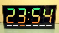
    Digital clock displaying colorful numbers 23:54 on an LED display.
    Very slow vertical color change.
    The remaining patterns are different display colors. There are 9 of them.
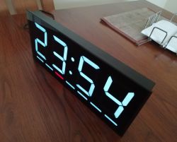
    Digital LED clock on a wooden table.

    Electronics:
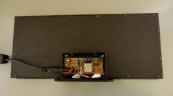
    Rear view of LED clock with visible electronics.

    I still have to think about the GUI. I am attaching the development code in the Arduino IDE.

    device diagram
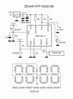
    Electronic schematic of an NTP clock with WS2812B LEDs.

    Well, that`s it in a nutshell :)

    Cool? Ranking DIY
    Do you have a problem with Arduino? Ask question. Visit our forum Arduino.
    About Author
    efi222
    Level 19  
    Offline 
    efi222 wrote 529 posts with rating 962, helped 6 times. Live in city Toruń. Been with us since 2019 year.
  • ADVERTISEMENT
  • #2 20854270
    krzbor
    Level 27  
    Very nice design, but the diagram looks interesting - only a few elements!
  • ADVERTISEMENT
  • #3 20854324
    efi222
    Level 19  
    With the exception of the ADC circuit for auto-adjusting the display brightness, these are the basic elements needed for the proper operation of the ESP8266.
  • #4 20854341
    michcz
    Level 11  
    The cock is very cool and aesthetic. Would there be a chance to make STL available? Maybe I`d finally have an excuse this Christmas to dust off the printer. :)

    You can get rid of striations on the focusing screen by exposing them to acetone vapor.
  • #5 20854445
    efi222
    Level 19  
    There is no problem with providing *.stl. I`ll tidy it up a bit and share it. I didn`t try anything with acetone. But these stripes are really hard to see. Maybe they even add charm :) . Matte is one layer from a 0.4 nozzle with a path width of 0.3. Thickness about 0.17 - 0.2. A lot depends on the table setting. All elements printed on glass.
  • #6 20854489
    madamsz1
    Level 41  
    efi222 wrote:
    After unsuccessfully searching for white PVC for matte screens

    Maybe something from a damaged TV matrix would meet the requirements. I used to have these nice 1mm sheets from an older one. Best with CCFL backlighting.
    Overall, a very nice project.
  • ADVERTISEMENT
  • #7 20854706
    efi222
    Level 19  
    In other projects, I used 0.16 mm thick PVC as mats. 1 mm is much too thick. At this thickness, the light from the segments will be scattered onto adjacent segments. Here, the wall between the segments is 0.6 mm thick with 1 mm masking. I tested the elements of the laptop`s LCD matrix and none of them were very suitable. But thanks for your interest :)

    @michcz. I uploaded the *.stl files to the main topic.
  • #8 20854711
    CMS
    Administrator of HydePark
    Very nice construction. I think that in this case these stripes add charm.
  • #10 20854796
    robig
    Level 23  
    michcz wrote:
    You can get rid of striations on the focusing screen by exposing them to acetone vapor.

    Acetone for PLA? It will not work, this method only with ABS and ASA. For PLA, chloroform, which you can`t buy, or sodium hydroxide, a strong base that is better not to play with.

    Efi222 - great idea and project!
  • #11 20854806
    LA72
    Level 41  
    robig wrote:
    michcz wrote:
    You can get rid of striations on the focusing screen by exposing them to acetone vapor.

    Acetone for PLA? It will not work, this method only with ABS and ASA. For PLA, chloroform, which you can`t buy, or sodium hydroxide, a strong base that is better not to play with.


    Spray plastic works great with PLA.
  • #12 20854913
    efi222
    Level 19  
    I will add from myself (I am writing from practice) that to print such a matting sheet you need to properly set the table and warm up the entire machine. Without this, each subsequent copy may come out slightly different. While this does not matter in normal prints, here you can immediately see the changes when the element is highlighted. The layer and pattern must be even. The backlight of such an element does not forgive any mistakes.

    In my opinion, further chemical operations can only worsen the effect. But these are only theoretical speculations :) Maybe someday I`ll mess around with chemistry. I`m also thinking about a print with a smaller nozzle passage and a narrower printing line.
  • #13 20855115
    Anonymous
    Level 1  
  • #14 20855139
    krzbor
    Level 27  
    You are right - the author did not notice that the ADC is up to 1V. Here is my solution for photoresistor-controlled backlighting Link . I used a large resistor to ground (1M) to achieve high resolution in low light, because this is when dimming is necessary.
    It is very easy to make a mistake when connecting the ADC. Such a NodeMCU has a divider at the input and the module pin actually works in the range of 0-3.3V, but this does not apply to the ESP8266 itself, which works in the range of 0-1V
  • #15 20855209
    gulson
    System Administrator
    A wonderful effect, contact me with information about the Parcel Locker and I will send you a small gift.
  • #16 20855310
    efi222
    Level 19  
    Mr. @Jarząbek and @krzbor, you are 100% right. You can get confused sometimes with ADC. I remembered this 1V range. But somewhere after that it went into the bushes :D
    The photoresistor is behind a dark glass, so it does not work very well in the bright resistance range.
    I selected the resistor at the ADC input to the ADC value. In a bright room it was about 800. So with some room. In the dark it was down to a dozen or so.
    The fact is that this range worked strangely in very bright rooms.
    So, after your comments, I measured... And now, in bright surroundings, I have 1.9 V, which is almost twice the range.
    But see for yourself in the video how it works. I only sped up the ADC reading interval from 300 to 100ms. Nothing suspicious :D
    I turn the lights on and off in the workshop.
    Thank you for your attention and perceptiveness :)


    Added after 19 [minutes]:

    krzbor wrote:
    I used a large resistor to ground (1M) to achieve high resolution in low light, because this is when dimming is necessary.

    In this system, the PWM changes exponentially. (in the code "curve_w[]") . At low values there is greater precision (less changes). This is due to our eyesight, which sees light logarithmically.
  • #17 20855376
    krzbor
    Level 27  
    efi222 wrote:
    In this system, the PWM changes exponentially. (in the code "curve_w[]") . At low values there is greater precision (less changes). This is due to our eyesight, which sees light logarithmically.

    That`s the point - vision works logarithmically and the ADC doesn`t (it`s linear). Using a large resistor gives reasonable results in low light conditions. Of course, in higher lighting there is almost a maximum ADC reading, but it does not matter. When it`s not dark, the LEDs can work at maximum anyway. Basically, what you have done (overdriving the ADC) is just using the lower voltage range (when it is dark).
  • #18 20855504
    khoam
    Level 42  
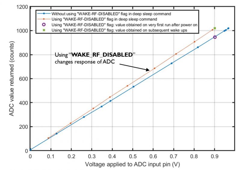
    The characteristics of the ADC in ESP8266 are as below. The maximum input voltage value of 1V should be considered optimistic.

    Graph showing ADC characteristics in ESP8266 with different WAKE_RF_DISABLED settings.

    @efi222 In the code you attached, you can see that you allocate arrays with constant values in RAM and flash, instead of just flash. I would suggest using the constexpr keyword.
  • ADVERTISEMENT
  • #19 20855565
    efi222
    Level 19  
    This is beyond my scope of knowledge at the moment. But I`ll try to educate myself. Thank you for your tips :)
  • #20 20855680
    urkotrebor
    Level 21  
    Some time ago, when I was playing with WS2812B diodes, I read that the control signal is 5V and you connect it directly to the ESP, did you have any problems with it?
    If I remember correctly, the library I used made it possible to read the values on individual diodes, so a feedback signal of 5V is tolerated by the ESP?
  • #21 20855710
    Andrzej42
    Level 31  
    As a matte, foil for insulating wires in engines. You can get it at any rewinding plant - I also have a lot of it, if anyone needs a few kilos...
  • #22 20855734
    efi222
    Level 19  
    In earlier designs, I used CD4050 as the driver between ESP and WS2812B. Here I tried without a driver. and It works without any problems.
    I read somewhere that earlier versions of WS2812, without the letter "B", had problems with 3.3V control. But now I won`t answer how reliable a source it was...
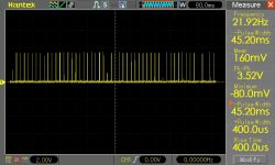
    The oscillogram shows the GPIO14 output with the WS2812B connected. 3.52V at peak
    Oscilloscope waveform from GPIO14 connected to WS2812B, showing peak voltage of 3.52V.


    @Andrzej42 I was interested in my friend`s information. Can you take a photo, at least for reference?

    Added after 3 [minutes]:

    urkotrebor wrote:
    If I remember correctly, the library I used made it possible to read the values on individual diodes

    Maybe it was about reading the status of the RGB WS2812B controller, what is currently set there?
  • #23 20855747
    khoam
    Level 42  
    efi222 wrote:
    The oscillogram shows the GPIO14 output with the WS2812B connected. 3.52V at peak

    Interesting. What is the actual supply voltage to the ESP?
  • #24 20855749
    efi222
    Level 19  
    You can also measure the voltage at the tape input in a static state. Only when power is connected.

    Added after 4 [minutes]:

    khoam wrote:
    What is the actual supply voltage to the ESP?

    3.29. On an oscilloscope, this is a software measurement. Well, it shows... Maybe it needs to be calibrated :) (oscilloscope)
    Well, there is no 5V there.
  • #25 20855763
    khoam
    Level 42  
    efi222 wrote:
    On an oscilloscope, this is a software measurement. Well, this is what it shows... Maybe it needs to be calibrated (oscilloscope)

    Necessarily, because it seems unreliable :)

    As for the WS2812B control, the catalog note for this system leaves no doubt that when the WS is powered with 5V, the minimum value in the high state for DIN is 3.5 V. Unless it is slightly less than 5V :)

    Electrical parameters table for an integrated circuit.
  • #26 20855767
    efi222
    Level 19  
    I even had space on the board for this driver. I`ll leave it as it is for now. The watches work for about a month.

    Added after 22 [minutes]:

    I also measured the static voltage at the input of the WS tape powered by 5V.
    Not counting individual millivolts, it is 0V.
  • #27 20855979
    krzbor
    Level 27  
    efi222 wrote:
    The oscillogram shows the GPIO14 output with the WS2812B connected. 3.52V at peak

    Unfortunately, this may be the effect of the "clamping diode" in ESP (3.52-3.29) = 0.23V, it looks like a Schottky protection diode. The problem is that there is no resistor between the ESP and the WS2812B. If there are feedback signals (of course 5V), some current may flow through this diode. I haven`t found what the max is in ESP8266 for these diodes. But it is safe to assume 1mA or less, so you would need a resistor of at least 2.2k. As @khoam mentioned, the WS2812B chip is slightly outside the high input voltage range. I also had such a problem once and I powered the system with 5V through a rectifier diode. A lower supply voltage will bring us within the range of 0.7VDD
  • #28 20856116
    khoam
    Level 42  
    krzbor wrote:
    Unfortunately, this may be the result of the "clamping diode" in ESP (3.52-3.29) = 0.23V, it looks like a Schottky protection diode.

    The permissible supply voltage for ESP8266 is 3.6V, so the "clamping diode" will probably not work at a voltage of 3.5V. That would be weird.
  • #29 20856139
    krzbor
    Level 27  
    khoam wrote:
    krzbor wrote:
    Unfortunately, this may be the effect of the "clamping diode" in ESP (3.52-3.29) = 0.23V, it looks like a Schottky protection diode.

    The permissible supply voltage for ESP8266 is 3.6V, so the "clamping diode" will probably not work at a voltage of 3.5V. That would be weird.

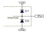
    "Clamping diode" is a diode connected between the pin and the power supply:
    Diagram showing two diodes connected between a pin and power supply and ground.
    It will always work when the pin potential is approximately 0.3V higher than the supply voltage. Therefore, if we power the ESP with a voltage of 3.29V, this diode will work with a voltage on the pin of approximately 3.59 - everything depends on the forward voltage of this diode. What is important - the diode is connected directly - there is no current limit. It`s easy to damage.
  • #30 20856164
    khoam
    Level 42  
    krzbor wrote:
    "Clamping diode" is a diode connected between the pin and the power supply:

    Are you sure this information comes from the manufacturer`s documentation? ;)

Topic summary

The discussion revolves around a user-created LED clock utilizing WS2812B LED strips, which synchronizes time via NTP servers. The clock features large digits (79 mm) and displays the days of the week. Participants commend the design and inquire about the availability of STL files for 3D printing. Technical aspects include the use of an ADC circuit for brightness adjustment and the challenges of controlling WS2812B LEDs with ESP8266, particularly regarding voltage levels and feedback mechanisms. Various suggestions for materials and methods to improve the display quality are shared, alongside discussions on the limitations of the ESP8266's ADC and the importance of using proper logic level converters for 5V compatibility.
Summary generated by the language model.
ADVERTISEMENT