logo elektroda
logo elektroda
X
logo elektroda

Guide: Control MagicHome Single Color LED WiFi Controller with BL602 & HomeAssistant

vinicius_trev  0 2304 Cool? (+1)
📢 Listen (AI voice):

TL;DR

  • A MagicHome single-color LED WiFi controller with a BL602 chip is repurposed for HomeAssistant control.
  • The board is opened, UART RX/TX pads are wired to an FTDI FT-232RL at 3v3, and BOOT is pulled to GND through 10K for flash mode.
  • Bouffalo Lab Dev Cube flashes OpenBK firmware after updating Factory Params, Partition Table, Boot2 Bin, and Firmware Bin paths; the LED supply is 5V-24V.
  • After reboot, an OpenBL602_XXXXXXXX WiFi network appears, the module serves a webpage at 192.168.169.1/index or 192.168.4.1, and P20 is configured as PWM.
  • The LED then toggles on and off, brightness adjusts, and HomeAssistant integration requires an MQTT broker configured to match the broker settings.
AI summary based on the discussion. May contain errors.
Since I didn't find any tutorials related to the Magic Home single-color LED controller I used this post as a starter/reference guide.


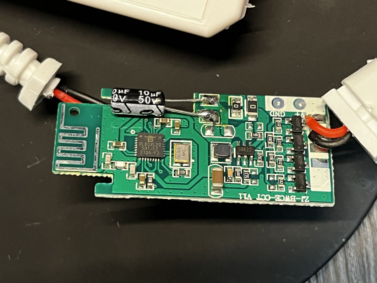
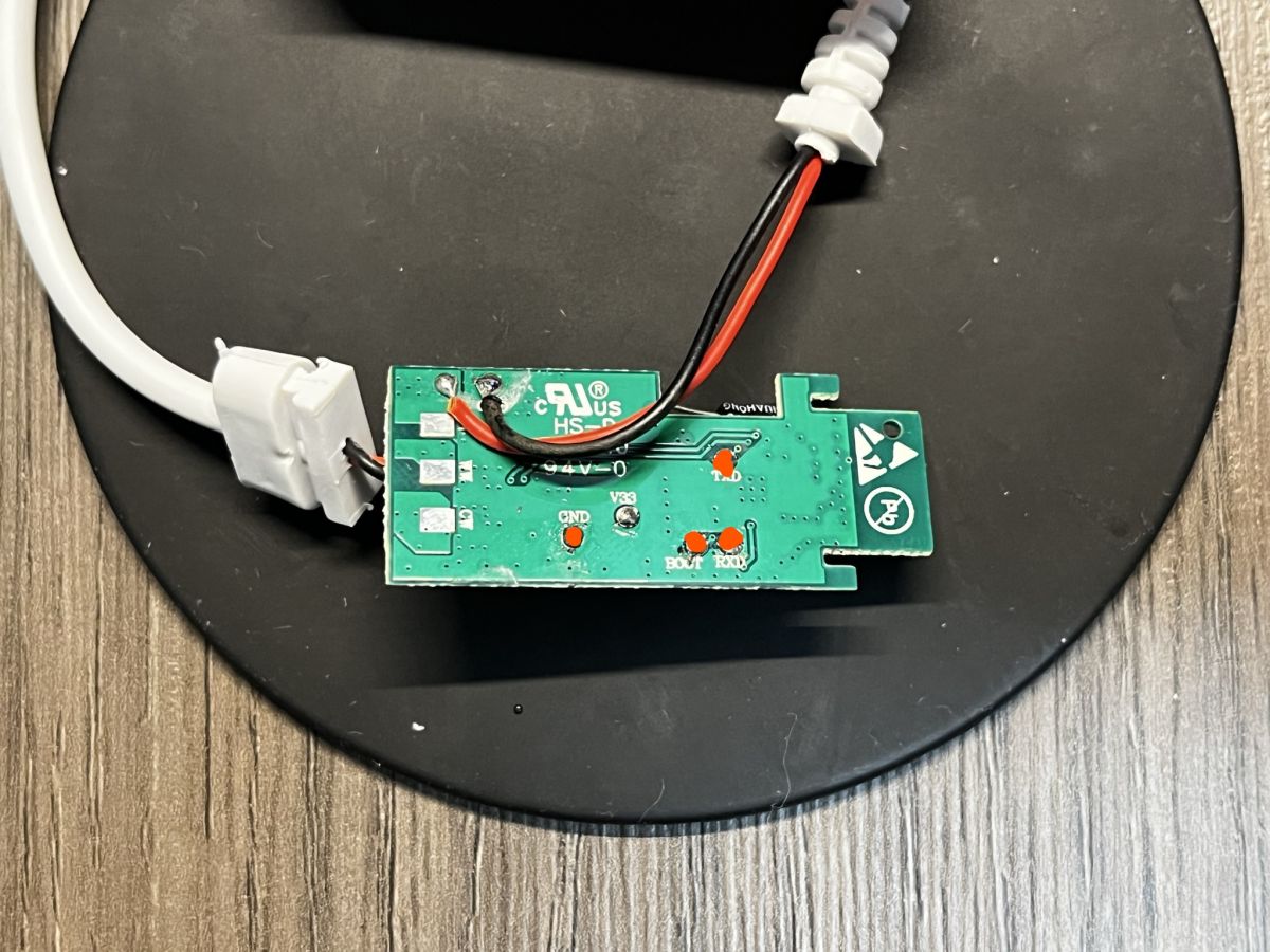
The main focus was only on controlling the LED PWM signal using HomeAssistant . As the first step, the device was disassembled, revealing the BL602 controller and the UART pins (RX, TX).


With the wires soldered to the pin pad, an FTDI FT-232RL was used to connect the soldered pins as the diagram below (remember to setup the FTDI device or any serial converter to 3v3 voltage as the BL602 uses that voltage on its pins). The BOOT pin was connected to GND in series with a 10K resistor, enabling the bootloader flash mode.

BL602FTDI
RXTX
TXRX
BOOTGND (series with 10K resistor)
GNDGND

*do not connect the VCC/V33 line*

Then, the device needs to be powered using the 5V-24V power supply (probably the same that you will use to power your LEDs. Note the positive and negative connectors, avoiding plugging them in reverse).

The flashing process is the same as described in this Elektroda youtube tutorial, using the Bouffalo Lab Dev Cube (BL Dev Cube) found here (note that the entire project needs to be clone/downloaded to access the "tools" folder).

The OpenBK firmware/binary that will be used to flash into the BL602 can be found here.

In the BL Dev Cube flashing software enable and update the binary paths at "Factory Params", "Partition Table", "Boot2 Bin" and "Firmware Bin", being this last one the binary that was recently downloaded. Create & Download the new firmware.

With the firmware flashed, the device can now be restarted, remember to remove the BOOT pin so the bootloader can load the firmware. A WiFi Network similar to "OpenBL602_XXXXXXXX", will pop up, being the 8Xes the MAC Address of the device's WiFi.

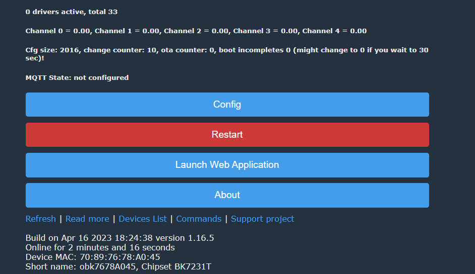
Connect to the WiFi network described previously and access the following IP address http://192.168.169.1/index (if that option didn't work try 192.168.4.1). A webpage similar to this one will appear:


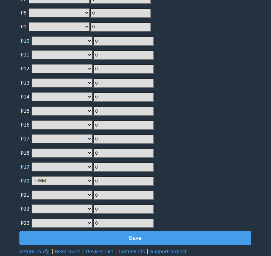
Now it is time to set up the GPIO to control the LEDs. Go to "Config" -> "Configure Module" then use the P20 as a PWM signal and save the settings


Return to the index page/main menu and your LED device should now be working. Toggle on and off the light, adjust the brightness and test the device.


To connect the device to HomeAssistant, you will need to have an MQTT broker installed and configured, use the Elektroda youtube tutorial as a guide, adjusting the tutorial based on you MQTT Broker settings.

About Author
vinicius_trev wrote 1 posts with rating 1 . Been with us since 2023 year.

Comments

FAQ

TL;DR: Flashing needs 3.3V UART and “do not connect the VCC/V33 line”; this FAQ helps Home Assistant users replace the MagicHome BL602 firmware with OpenBK, set PWM on GPIO P20, and link the single-color LED controller through MQTT. [#20546342] Why it matters: Correct 3.3V serial wiring, BOOT handling, and P20 PWM setup prevent flashing failures and make the LED dimmer usable in Home Assistant.

Option Specific value Use in the setup
Primary setup IP 192.168.169.1/index OpenBL602 configuration page after joining its WiFi
Fallback setup IP 192.168.4.1 Try if the primary address fails
UART logic level 3.3V Required for BL602 pins
Controller power input 5V–24V Powers the MagicHome LED controller during flashing

Key insight: The BL602 MagicHome single-color controller works after flashing when UART uses 3.3V, BOOT is grounded only for flash mode, and GPIO P20 is assigned as the PWM output.

Quick Facts

  • The MagicHome single-color LED controller in the thread exposes BL602 UART pads labeled RX and TX for flashing access. [#20546342]
  • The FTDI FT-232RL serial adapter must use 3.3V logic because the BL602 uses 3.3V on its pins. [#20546342]
  • The BOOT pin connects to GND through a 10K resistor to enable bootloader flash mode. [#20546342]
  • The controller needs its own 5V–24V power supply during flashing, and the post warns not to reverse polarity. [#20546342]
  • OpenBK configuration uses GPIO P20 as the PWM signal for the single-color LED output. [#20546342]

How do I flash OpenBK firmware onto a MagicHome single-color LED WiFi controller with a BL602 chip?

Flash OpenBK by wiring UART, entering BL602 bootloader mode, then using Bouffalo Lab Dev Cube.
  1. Solder RX, TX, BOOT, and GND wires to the controller pads.
  2. Connect FTDI at 3.3V logic and power the controller from 5V–24V.
  3. Load OpenBK files in BL Dev Cube, create, and download the firmware. Remove the BOOT connection after flashing so the firmware can start normally. [#20546342]

What is the BL602 chip used in the MagicHome LED WiFi controller?

The BL602 is the controller chip inside this MagicHome single-color LED WiFi controller. "BL602 is a WiFi microcontroller that runs the LED controller firmware, exposes UART RX/TX pads for flashing, and uses 3.3V logic on its pins." The thread identifies it after disassembly and flashes it with OpenBK/OpenBL602 firmware. [#20546342]

How should I wire a BL602-based MagicHome controller to an FTDI FT-232RL adapter for flashing?

Wire UART cross-over and ground reference, without connecting FTDI power. Connect BL602 RX to FTDI TX, BL602 TX to FTDI RX, BOOT to GND through a 10K resistor, and GND to GND. Set the FTDI FT-232RL to 3.3V logic before attaching it to the controller. [#20546342]

Why should the FTDI serial adapter be set to 3.3V when connecting to the BL602 UART pins?

Set the FTDI adapter to 3.3V because the BL602 uses 3.3V on its pins. The post explicitly warns to configure the FTDI device, or any serial converter, for 3V3 voltage. Using a different logic level risks unreliable serial communication or hardware damage during flashing. [#20546342]

What is the BOOT pin on a BL602, and why is it connected to GND through a 10K resistor during flashing?

The BOOT pin selects the BL602 bootloader flash mode when pulled to GND through 10K. "BOOT is a hardware mode-select pin that makes the BL602 start its flashing bootloader, allowing BL Dev Cube to write firmware over UART." After flashing, disconnect BOOT from GND so OpenBK can boot normally. [#20546342]

Why should I avoid connecting the VCC or V33 line from the FTDI adapter to the MagicHome BL602 controller?

Avoid FTDI VCC or V33 because the controller must be powered by its own 5V–24V supply. The thread gives a direct warning: “do not connect the VCC/V33 line.” Only RX, TX, BOOT, and GND are used from the serial adapter in the wiring table. [#20546342]

How do I use Bouffalo Lab Dev Cube to flash OpenBK onto a BL602 LED controller?

Use Bouffalo Lab Dev Cube by setting the required binary paths and running Create & Download. The post says to enable and update Factory Params, Partition Table, Boot2 Bin, and Firmware Bin. The Firmware Bin is the OpenBK binary downloaded from the OpenBK7231T_App releases page. [#20546342]

What OpenBK binary files and BL Dev Cube settings are needed for flashing a BL602 device?

BL Dev Cube needs four enabled binary paths: Factory Params, Partition Table, Boot2 Bin, and Firmware Bin. The Firmware Bin should be the downloaded OpenBK firmware binary for the BL602 target. The flashing tool comes from the OpenBL602 project tools folder, which requires cloning or downloading the full project. [#20546342]

How do I access the OpenBL602 web configuration page after flashing the MagicHome controller?

Access the configuration page by joining the OpenBL602 WiFi network and opening 192.168.169.1/index. The network name appears similar to OpenBL602_XXXXXXXX, where the 8 X characters represent the device WiFi MAC address. If that address fails, try 192.168.4.1 as the fallback IP. [#20546342]

Which GPIO pin controls PWM output on the MagicHome single-color BL602 LED controller?

GPIO P20 controls the PWM output on this MagicHome single-color BL602 LED controller. The thread configures P20 as the PWM signal under Config → Configure Module. After saving, the main page can toggle the light and adjust brightness. [#20546342]

What is PWM control, and how does it adjust brightness on a single-color LED strip?

PWM control adjusts the LED brightness by driving the single-color output with a pulsed signal on P20. "PWM is a control method that varies output duty cycle, making an LED strip appear dimmer or brighter without changing its configured color channel." In this setup, OpenBK exposes on/off and brightness controls after P20 is assigned. [#20546342]

How do I configure GPIO P20 as a PWM output in OpenBK for a MagicHome LED controller?

Configure P20 by opening the OpenBK web page, then choosing Config → Configure Module. Set P20 as a PWM signal and save the settings. Return to the index page, toggle the LED, and test brightness adjustment from the OpenBK interface. [#20546342]

What is an MQTT broker, and why is it needed to connect an OpenBK LED controller to Home Assistant?

An MQTT broker is required so Home Assistant can communicate with the OpenBK LED controller. "MQTT broker is a message-routing service that receives and forwards device topics, letting Home Assistant control OpenBK lights through configured network messages." The thread says to install and configure an MQTT broker before linking the device to Home Assistant. [#20546342]

Bouffalo Lab Dev Cube vs other serial flashing tools: which is better for flashing BL602-based MagicHome controllers?

Bouffalo Lab Dev Cube is the documented tool for this BL602 MagicHome flashing procedure. The thread does not compare other serial flashing tools. It specifically uses BL Dev Cube from the OpenBL602 tools folder and follows an Elektroda BL602 flashing tutorial. [#20546342]

What should I check if the OpenBL602 WiFi network or the 192.168.169.1 configuration page does not appear after flashing?

Check BOOT removal, WiFi SSID, and the fallback IP if the setup page does not appear. After flashing, remove the BOOT-to-GND connection so firmware can load. Then look for an OpenBL602_XXXXXXXX network and try 192.168.169.1/index first, followed by 192.168.4.1. [#20546342]
AI summary based on the discussion. May contain errors.
%}