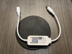
Since I didn't find any tutorials related to the Magic Home single-color LED controller I used this post as a starter/reference guide.
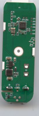
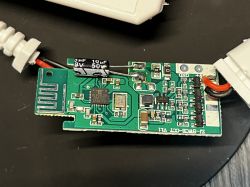
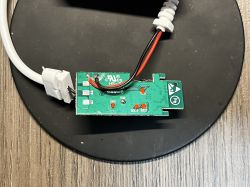
The main focus was only on controlling the LED PWM signal using HomeAssistant . As the first step, the device was disassembled, revealing the BL602 controller and the UART pins (RX, TX).
With the wires soldered to the pin pad, an FTDI FT-232RL was used to connect the soldered pins as the diagram below (remember to setup the FTDI device or any serial converter to 3v3 voltage as the BL602 uses that voltage on its pins). The BOOT pin was connected to GND in series with a 10K resistor, enabling the bootloader flash mode.
*do not connect the VCC/V33 line*
Then, the device needs to be powered using the 5V-24V power supply (probably the same that you will use to power your LEDs. Note the positive and negative connectors, avoiding plugging them in reverse).
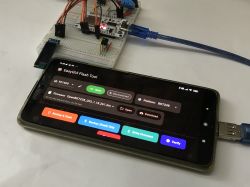
The flashing process is the same as described in this Elektroda youtube tutorial, using the Bouffalo Lab Dev Cube (BL Dev Cube) found here (note that the entire project needs to be clone/downloaded to access the "tools" folder).
The OpenBK firmware/binary that will be used to flash into the BL602 can be found here.
In the BL Dev Cube flashing software enable and update the binary paths at "Factory Params", "Partition Table", "Boot2 Bin" and "Firmware Bin", being this last one the binary that was recently downloaded. Create & Download the new firmware.
With the firmware flashed, the device can now be restarted, remember to remove the BOOT pin so the bootloader can load the firmware. A WiFi Network similar to "OpenBL602_XXXXXXXX", will pop up, being the 8Xes the MAC Address of the device's WiFi.
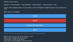
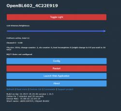
Connect to the WiFi network described previously and access the following IP address http://192.168.169.1/index (if that option didn't work try 192.168.4.1). A webpage similar to this one will appear:
Now it is time to set up the GPIO to control the LEDs. Go to "Config" -> "Configure Module" then use the P20 as a PWM signal and save the settings
Return to the index page/main menu and your LED device should now be working. Toggle on and off the light, adjust the brightness and test the device.
To connect the device to HomeAssistant, you will need to have an MQTT broker installed and configured, use the Elektroda youtube tutorial as a guide, adjusting the tutorial based on you MQTT Broker settings.
The main focus was only on controlling the LED PWM signal using HomeAssistant . As the first step, the device was disassembled, revealing the BL602 controller and the UART pins (RX, TX).
With the wires soldered to the pin pad, an FTDI FT-232RL was used to connect the soldered pins as the diagram below (remember to setup the FTDI device or any serial converter to 3v3 voltage as the BL602 uses that voltage on its pins). The BOOT pin was connected to GND in series with a 10K resistor, enabling the bootloader flash mode.
| BL602 | FTDI | RX | TX | TX | RX | BOOT | GND (series with 10K resistor) | GND | GND |
*do not connect the VCC/V33 line*
Then, the device needs to be powered using the 5V-24V power supply (probably the same that you will use to power your LEDs. Note the positive and negative connectors, avoiding plugging them in reverse).
The flashing process is the same as described in this Elektroda youtube tutorial, using the Bouffalo Lab Dev Cube (BL Dev Cube) found here (note that the entire project needs to be clone/downloaded to access the "tools" folder).
The OpenBK firmware/binary that will be used to flash into the BL602 can be found here.
In the BL Dev Cube flashing software enable and update the binary paths at "Factory Params", "Partition Table", "Boot2 Bin" and "Firmware Bin", being this last one the binary that was recently downloaded. Create & Download the new firmware.
With the firmware flashed, the device can now be restarted, remember to remove the BOOT pin so the bootloader can load the firmware. A WiFi Network similar to "OpenBL602_XXXXXXXX", will pop up, being the 8Xes the MAC Address of the device's WiFi.
Connect to the WiFi network described previously and access the following IP address http://192.168.169.1/index (if that option didn't work try 192.168.4.1). A webpage similar to this one will appear:
Now it is time to set up the GPIO to control the LEDs. Go to "Config" -> "Configure Module" then use the P20 as a PWM signal and save the settings
Return to the index page/main menu and your LED device should now be working. Toggle on and off the light, adjust the brightness and test the device.
To connect the device to HomeAssistant, you will need to have an MQTT broker installed and configured, use the Elektroda youtube tutorial as a guide, adjusting the tutorial based on you MQTT Broker settings.
Cool? Ranking DIY


