Hi,
Like many perhaps I bought a Magic home controller expecting to flash Tasmota onto it and go from there...
Turns out there is a different chip in side, and there you go down the rabbit hole. Thanks to someone with, I guess, a lot of perseverance and this beautiful community I could get this controller Magic home Wifi Led controller rgb + cct:
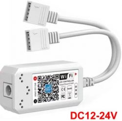
with what turned out to be a BL602 chip inside to work.
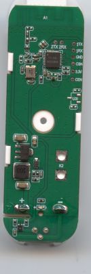
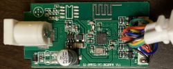
The insides, front and back are show below:
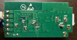
The PCB identification read ZJ-BWCG-VC-RGBWW V1.1
Chip close-up attempt:
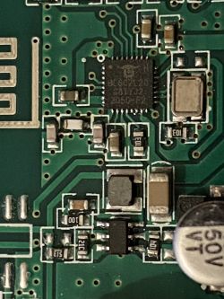
It took some tracing and measuring but I found the correct pinout for all channels and though I give something back to the community.
The configuration I entered worked for me:
P3 PWM Channel 2 / Green
P4 PWM Channel 0 / Red
P17 PWM Channel 3 / Cool white
P20 PWM Channel 4 / Warm white
P21 PWM Channel 1 / Blue
Many thanks!
Like many perhaps I bought a Magic home controller expecting to flash Tasmota onto it and go from there...
Turns out there is a different chip in side, and there you go down the rabbit hole. Thanks to someone with, I guess, a lot of perseverance and this beautiful community I could get this controller Magic home Wifi Led controller rgb + cct:

with what turned out to be a BL602 chip inside to work.
The insides, front and back are show below:

The PCB identification read ZJ-BWCG-VC-RGBWW V1.1
Chip close-up attempt:

It took some tracing and measuring but I found the correct pinout for all channels and though I give something back to the community.
The configuration I entered worked for me:
P3 PWM Channel 2 / Green
P4 PWM Channel 0 / Red
P17 PWM Channel 3 / Cool white
P20 PWM Channel 4 / Warm white
P21 PWM Channel 1 / Blue
Many thanks!
Cool? Ranking DIY


