Teardown and flashing of a Merkury Smart Wi‑Fi LED Strip, part number MI-EW014-999W, built around a WB3S BK7231T module.
The strip uses RGB PWM for red, green, and blue, and the PCB appears to include support for RGBW with missing components.
It draws approximately 10 watts on full white, and a 5W power supply caused discoloration until replaced with a 10W supply.
OpenBeken flashed over UART after soldering short Dupont wires to the chipset, then the pins were mapped as 1 Btn, 9 PWM1, 24 PWM2, and 26 PWM3.
The strip ran warm during operation, and the unused RGBW circuitry suggests a possible different part-number variant.
AI summary based on the discussion. May contain errors.
Hi,
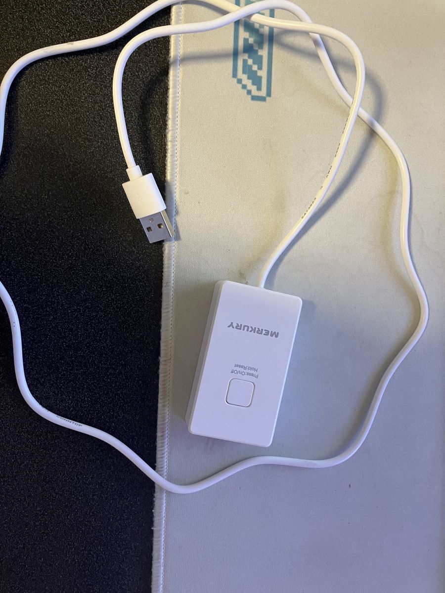
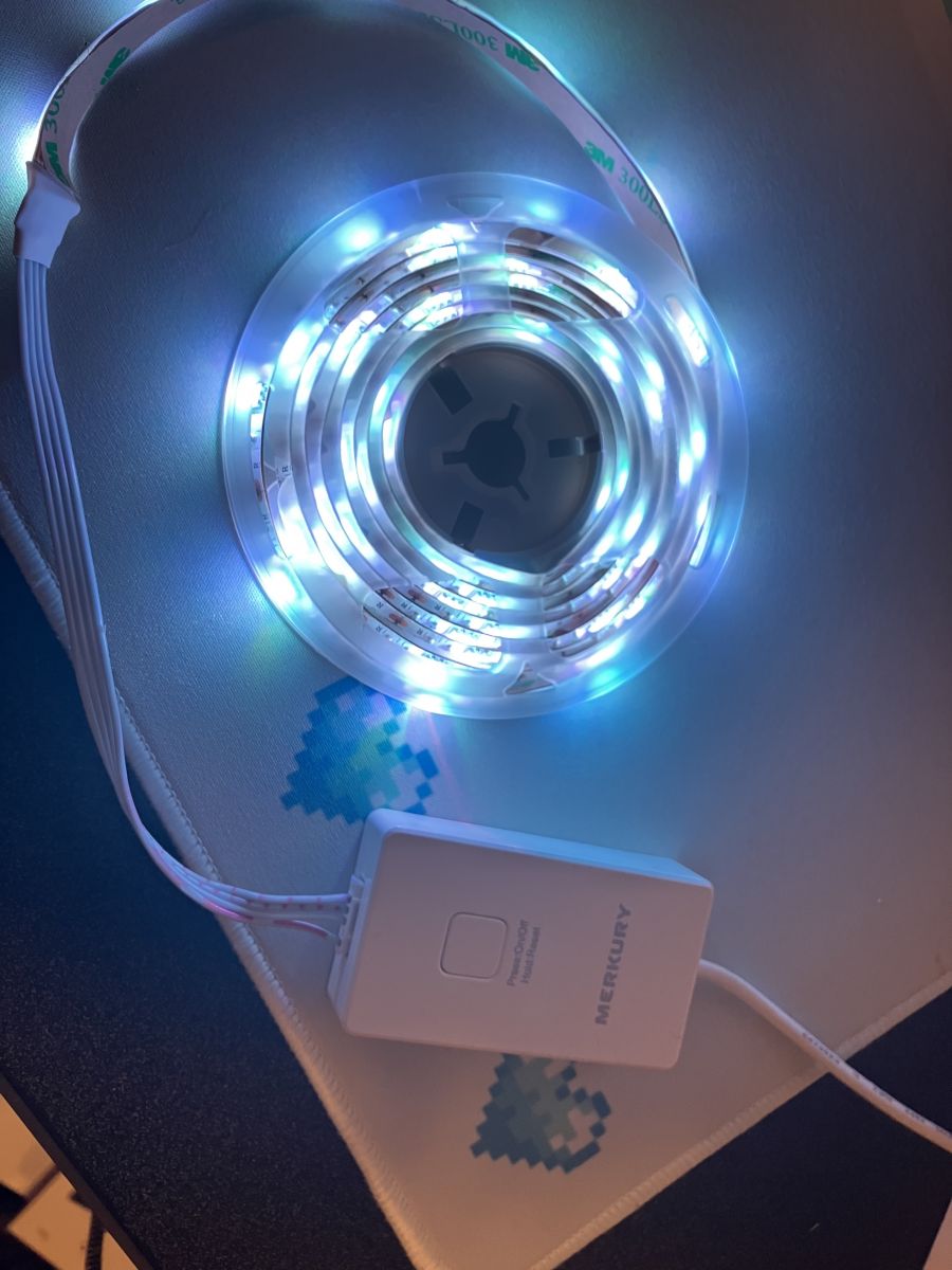
I am adding a teardown and flashing of Merkury RGB LED Strip. I got this device as part of a Walmart bundle with a Google Home Mini as a Black Friday deal. It is a USB Powered RGB strip, using RGB PWM to power the 3 colors LEDs on the strip. This strip also draws a rather signifcant amount of power, approximately 10 watts on full white. I don't think this ever really sold outside of the bundle with it's part number, but here is the walmart link https://www.walmart.com/ip/Merkury-Innovation...36653?wmlspartner=wlpa&selectedSellerId=18118.
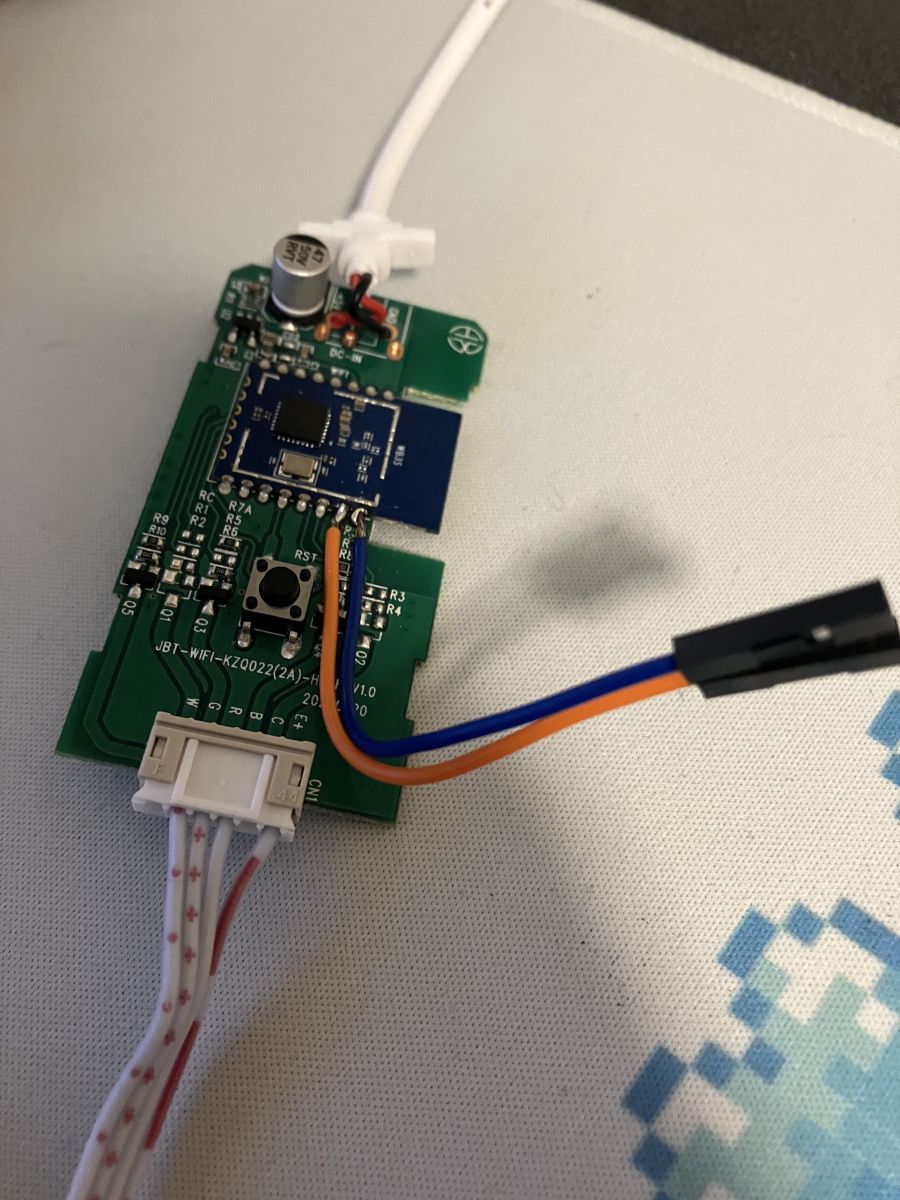
After getting the item I realized that esphome couldn't be put on the device, and figured out what getting OpenBeken flashed onto it would take. The case just snaps together with relative ease, so after taking that off I saw quit a lot room, so I decided to take just solder some short dupont ended wires and folding them into the case afterwards to make flashing/reflashing over UART easier if I wanted to try build my own application on it.
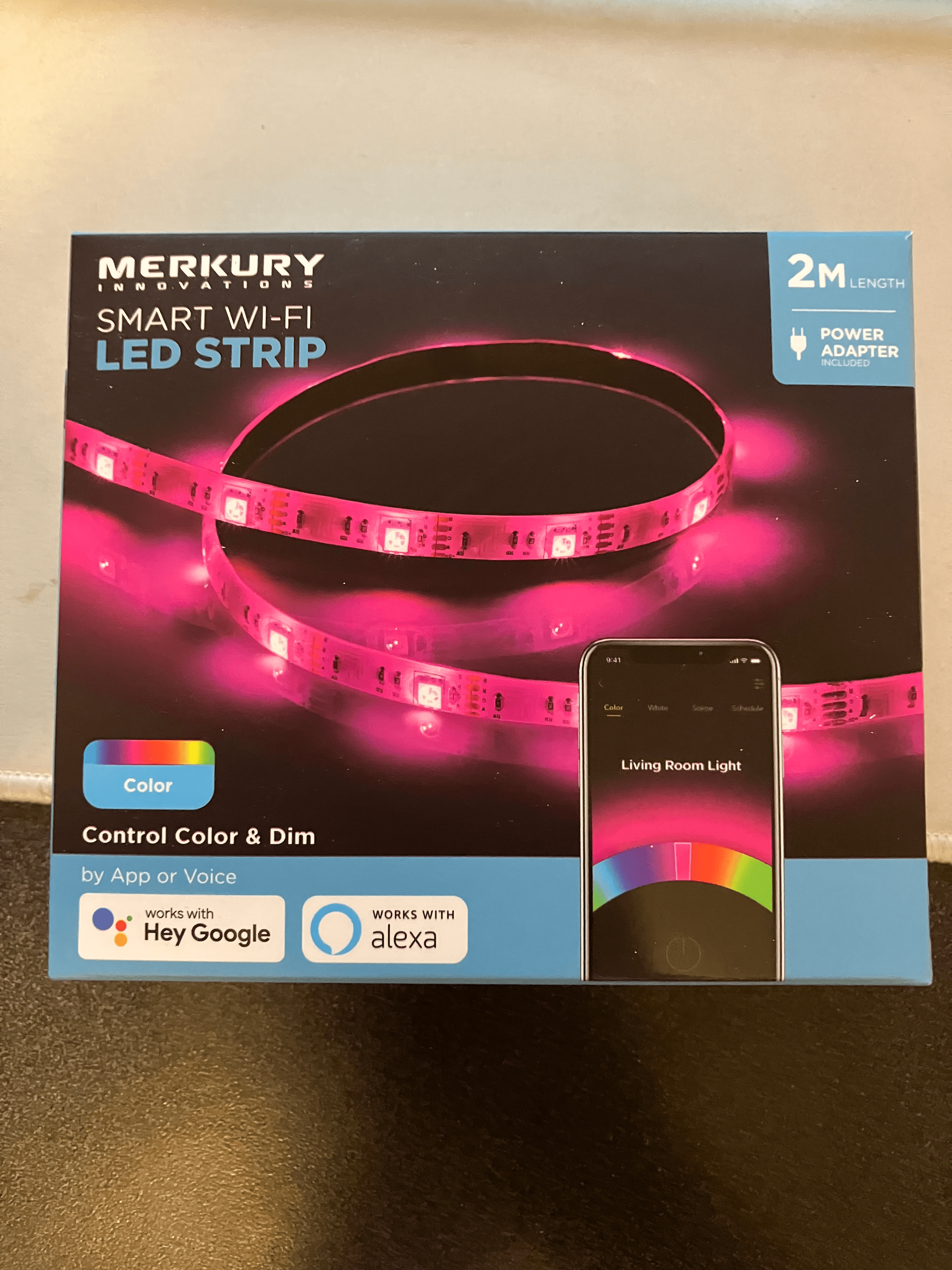
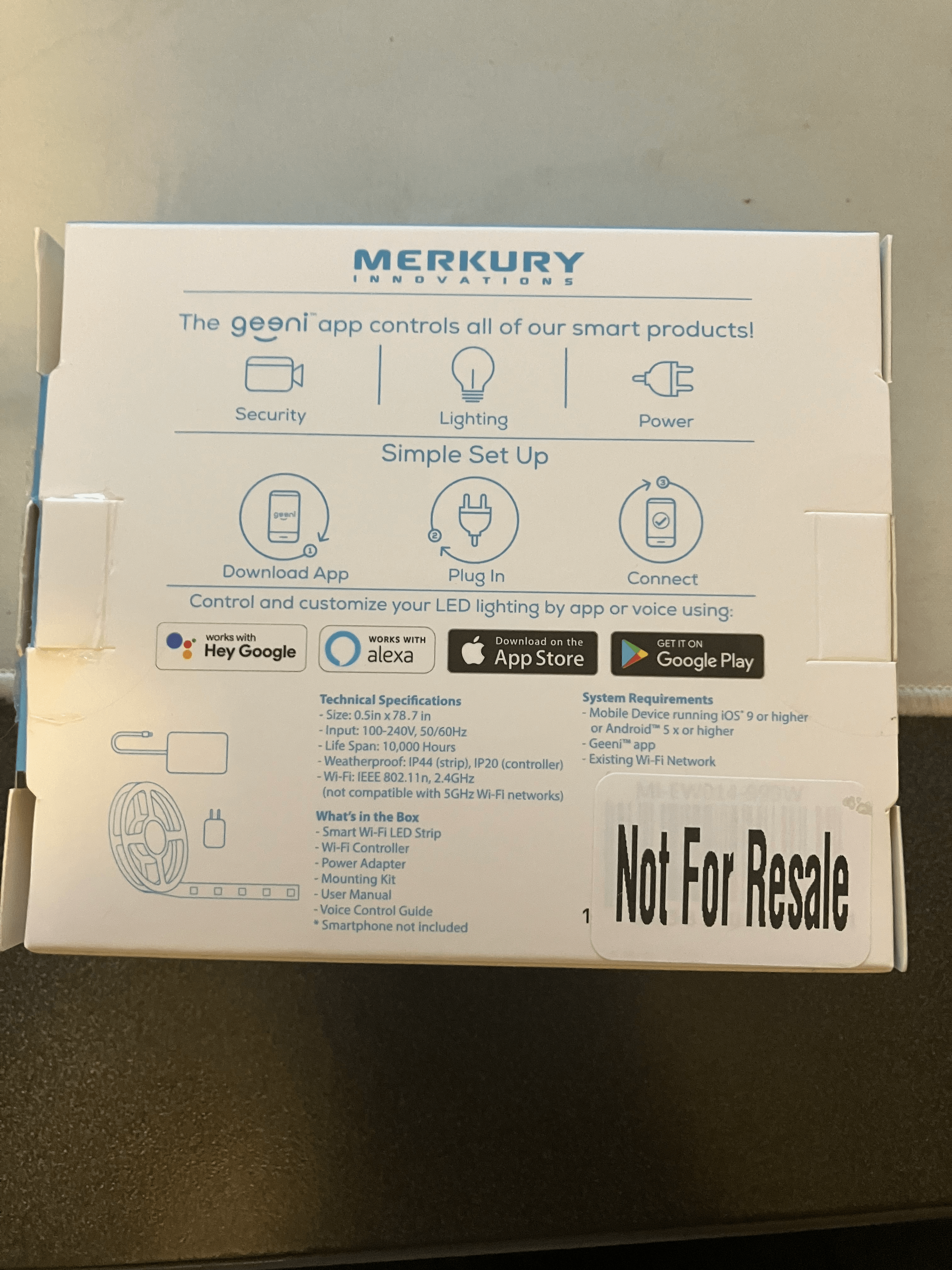
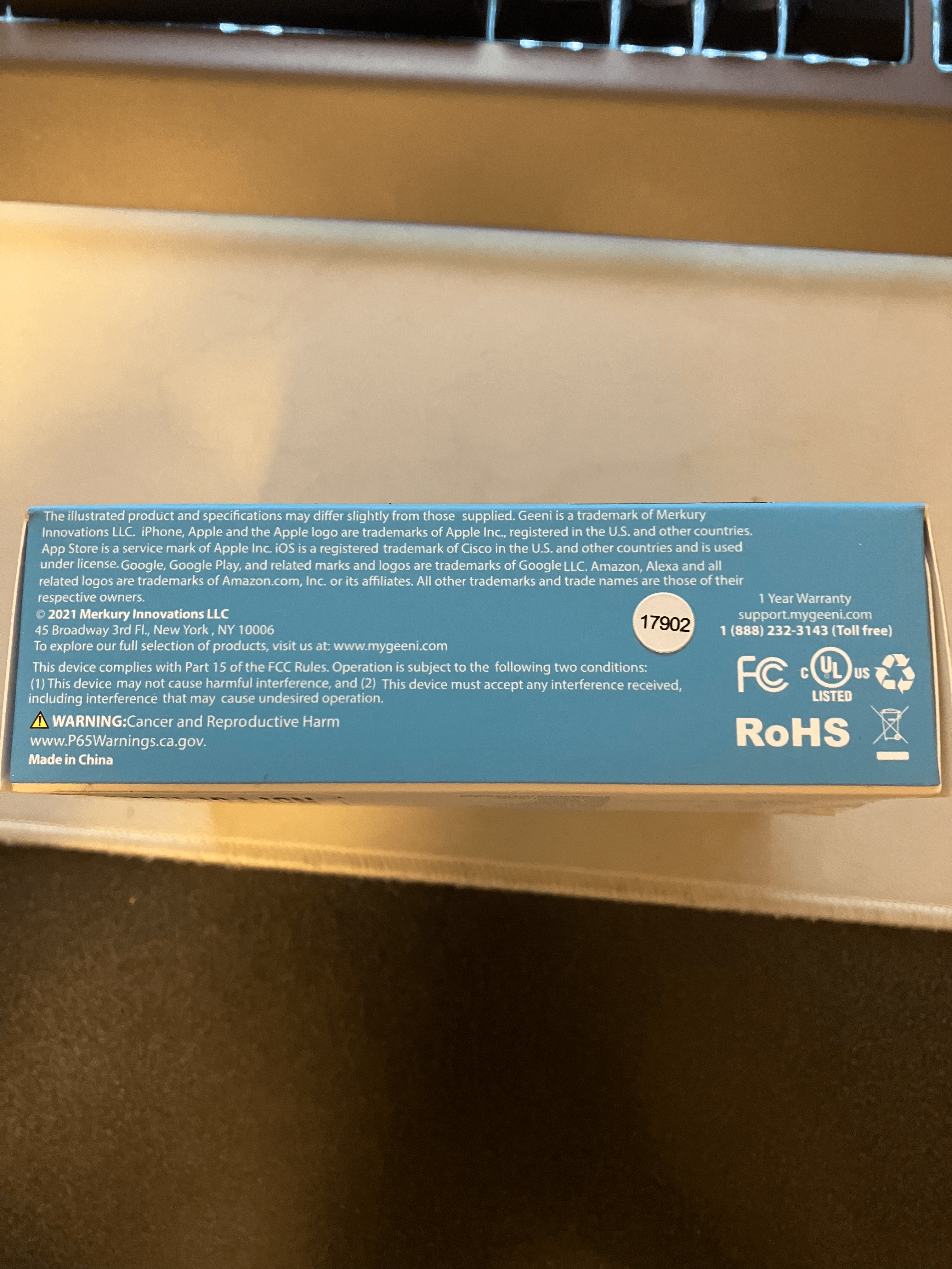
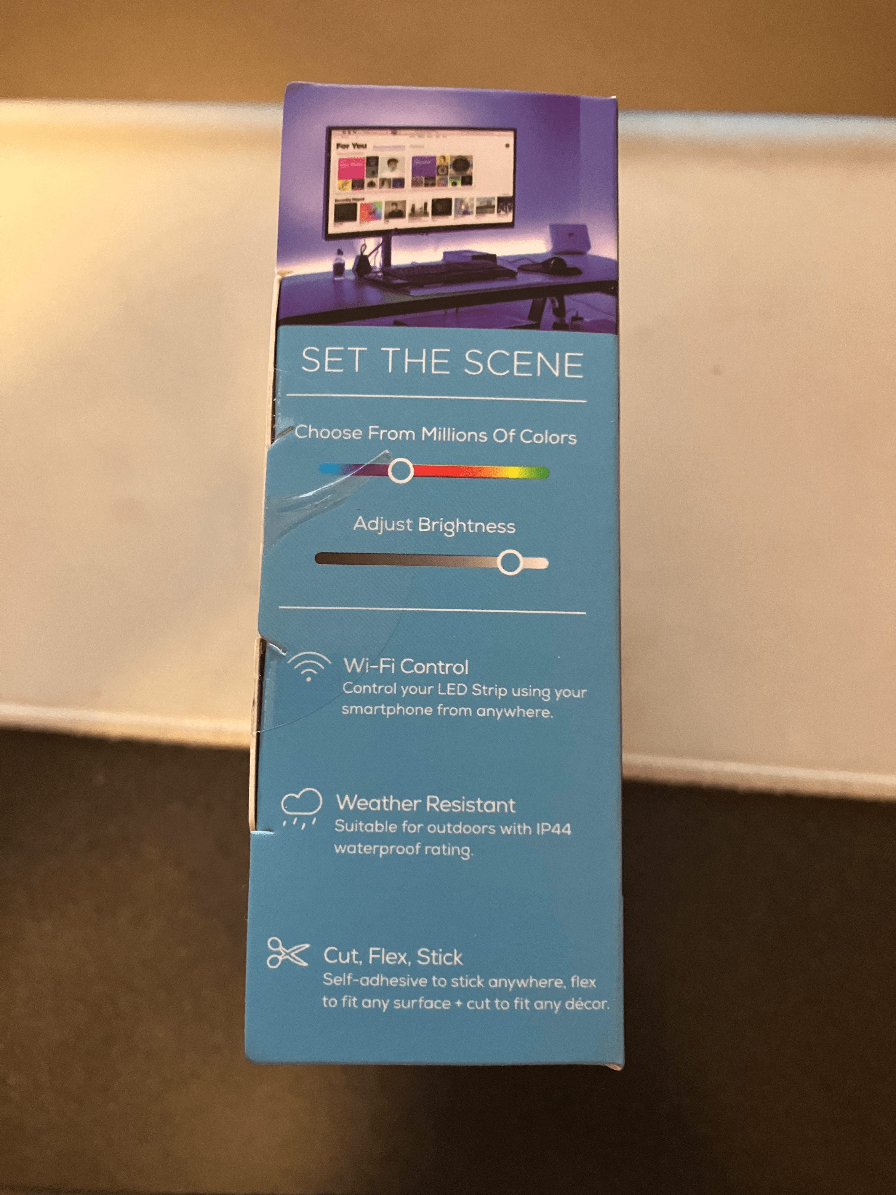
Packaging:
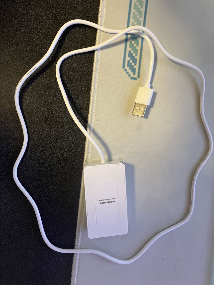
Appearance:
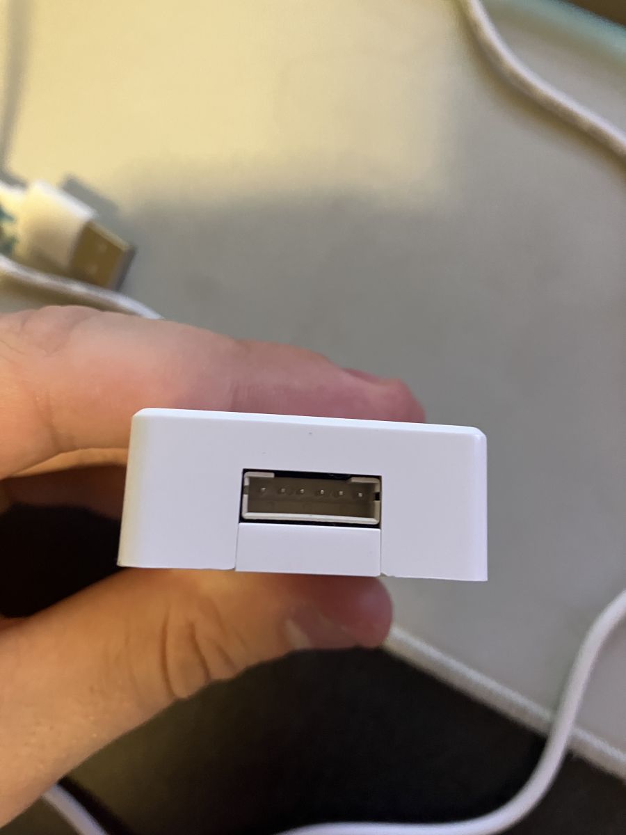
Main body:
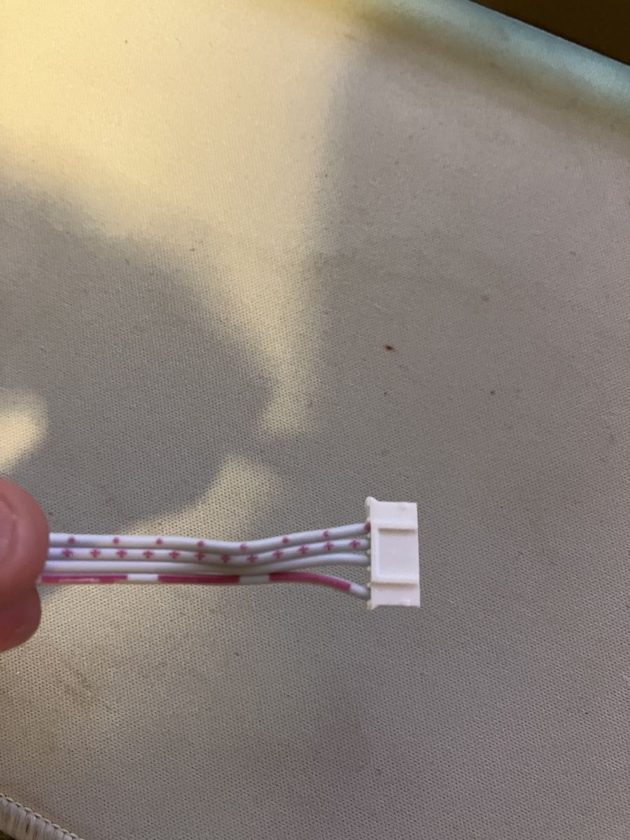
I did find it interesting that the main body says RGBW, and the socket supports RGBW, when this only and RGB strip. The circuit board also the circuitry for the W, so that makes me wonder if this was sold as an RGBW strip as a different part-number in which case the teardown and flashing would look similar.
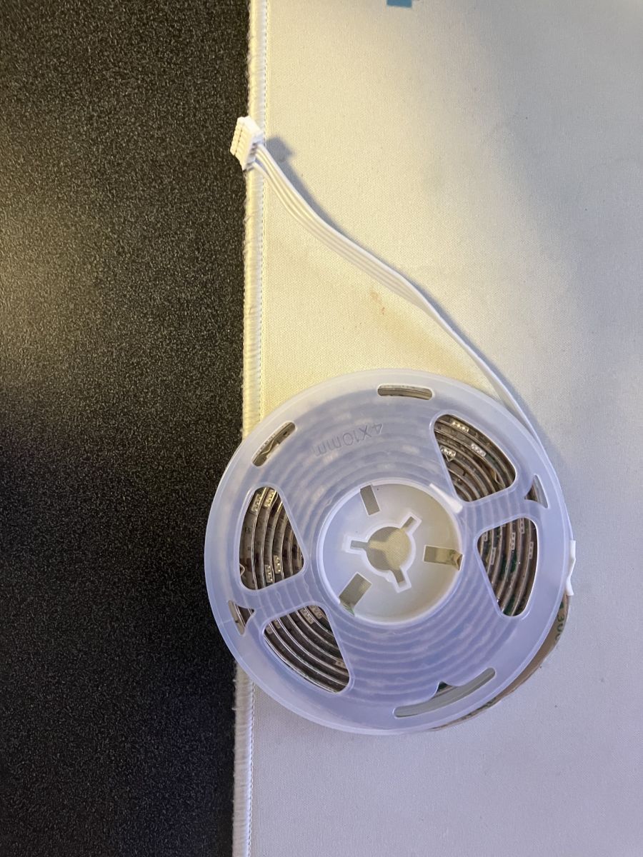
LED Strip:
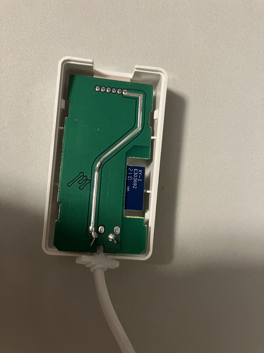
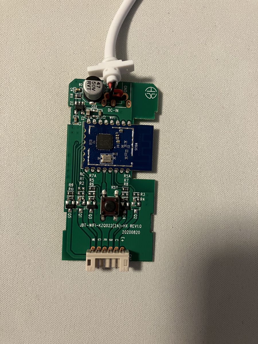
Circuit Board:
The board is powered by the WB3S chipset, and just has a very small number of components. It is interesting to note that the board appears to completely support RGBW if you solder on the missing components.
New UART:
I soldered these short dupont cables onto the UART of the chipset to making connecting my generic USB-UART adapter easier if I ever need to use it again. Flashing then went easy with the generic bin, over UART.
After getting it connected to the Wi-Fi. I got the pins configured
1 - Btn
9 - PWM1 (Red)
24 - PWM2 (Green)
26 - PWM3 (Blue)
After these were set, it auto detected it as an RGB Strip, and just worked. On a 5W power supply, the LEDs were drawing too much causing discoloration, but that was fixed with a 10W supply. The role of strip get rather warm if left like this for a while. Unsure if it could ever get hot enough to cause damage, but something to note.
Attachments:
MerkuryRGB.json.txt(480 Bytes)
You must be logged in to download this attachment.
About Author
trwbox wrote 1 posts with
rating 1 , helped 1 times.
Been with us since 2023 year.
Very good teardown, thank you for flashing it. It's nice to see that at least this device has a button. I had some strips that came without a button and had to modify them to have one:
Make sure to... [Read more]
mchipser
24 Apr 2024 23:52
I have a similar model, but I cant figured out the config to use.. MI-EW011-999W. I was able to get it flashed to OpenBK, but not sure how to configure it.. [Read more]
I tried it on a second one.. this is what I get..
https://obrazki.elektroda.pl/2079246400_1714158811_thumb.jpg
{
"abi":"0",
"id":"null",
"swv":"1.0.5",
"bv":"40.00",
"pv":"2.2",
"lpv":"3.3",
"pk":"keyr4unj7kauxym4",
"firmk":"keyr4unj7kauxym4",
"cadv":"1.0.3",
"cdv":"1.0.0",
"dev_swv":"1.0.5",
"s_id":"null",
"dtp":"0",
"sync":"0",
"attr_num":"0",
"mst_tp_0":"0",
"mst_ver_0":"null",
"mst_tp_1":"0",
"mst_ver_1":"null",
"mst_tp_2":"0",
"mst_ver_2":"null",
"mst_tp_3":"0",
"mst_ver_3":"null... [Read more]
p.kaczmarek2
27 Apr 2024 08:25
If there is no decodable configuration in your Tuya JSON partition, then the next step is to use the GPIO doctor tool from the OBK Web App. Use it to check each GPIO one by one and note which LEDs are... [Read more]
FAQ
TL;DR: For a 2 m Merkury MI-EW014-999W RGB strip, “just worked” after UART flashing OpenBeken and setting pins 1, 9, 24, and 26; use a 10 W USB supply to avoid full-white discoloration. This FAQ helps BK7231T/WB3S owners flash and configure the strip. [#20570050]
Why it matters: The thread gives a working OpenBeken pin map and power warning for a real Merkury USB LED strip teardown.
Alternative
Thread result
Best use
Limitation
OpenBeken
Flashed successfully over UART
BK7231T/WB3S Merkury strip control
Needs GPIO setup
ESPHome
Not installed on this device
ESP-based devices
The author could not put ESPHome on this strip
Key insight: The MI-EW014-999W controller exposes enough hardware for RGBW, but the shipped 2 m LED strip is RGB. OpenBeken works once RGB PWM pins and the button are assigned.
Quick Facts
The Merkury MI-EW014-999W strip is USB powered, 2 m / 6.5 ft long, and uses RGB PWM for three LED colors. [#20570050]
Full white draws approximately 10 W, while a 5 W supply caused visible discoloration. [#20570050]
Working OpenBeken roles are GPIO 1 as button, GPIO 9 as PWM red, GPIO 24 as PWM green, and GPIO 26 as PWM blue. [#20570050]
The controller case snaps open, and the author soldered short Dupont-ended UART wires for easier reflashing. [#20570050]
For unknown models such as MI-EW011-999W, use Tuya config extraction first, then GPIO Doctor if the JSON is not decodable. [#21061913]
How do I flash OpenBeken onto a Merkury Smart Wi-Fi LED Strip MI-EW014-999W with a BK7231T WB3S module over UART?
Flash OpenBeken over UART using a generic BK7231T binary and a USB-UART adapter.
Snap open the controller case.
Solder short Dupont wires to the WB3S UART pads.
Flash the generic OpenBeken binary, then connect the device to Wi-Fi.
The author kept the wires folded inside the case for later reflashing. [#20570050]
What GPIO pin configuration should I use in OpenBeken for the Merkury MI-EW014-999W RGB LED strip?
Use GPIO 1 for the button, GPIO 9 for red, GPIO 24 for green, and GPIO 26 for blue. Set GPIO 9 to PWM1, GPIO 24 to PWM2, and GPIO 26 to PWM3. After those roles were set, OpenBeken detected the device as an RGB strip. The strip then worked normally on Wi-Fi. [#20570050]
How should the button on a Merkury RGB LED strip be configured in OpenBeken for brightness and color control?
Configure the physical button as Btn_SmartLED, not only as a plain button. The responder specifically recommended Btn_SmartLED for “all nice features,” including single-button brightness control. The MI-EW014-999W has its button on GPIO 1. This matters because some LED strip controllers lack a button entirely. [#20570104]
What is the Btn_SmartLED role in OpenBeken and what features does it add for LED strip buttons?
Use Btn_SmartLED as the OpenBeken button role for smart LED strip control. "Btn_SmartLED" is an OpenBeken GPIO role that turns one physical button into an LED-strip control input, adding behaviors such as single-button brightness handling instead of only basic on/off switching. The thread explicitly names brightness control as a feature. [#20570104]
Why does the Merkury MI-EW014-999W controller say RGBW when the included LED strip is only RGB?
The controller appears built for RGBW, but the included strip uses only RGB. The main body says RGBW, the socket supports RGBW, and the PCB includes circuitry for a white channel. The author noted missing components could be soldered for fuller RGBW support. This suggests a similar RGBW variant may share the same controller design. [#20570050]
How much power supply capacity does the Merkury MI-EW014-999W USB RGB LED strip need to avoid discoloration at full white?
Use a 10 W USB power supply for full-white operation. The strip drew approximately 10 W on full white during testing. A 5 W power supply caused the LEDs to draw too much current and discolor. Switching to a 10 W supply fixed the issue. [#20570050]
Why does a USB-powered RGB LED strip change color or look wrong when powered from a 5W supply?
It changes color because the 5 W supply cannot support the strip at full white. Full white uses all three RGB channels together. In the test, the LEDs drew too much power from a 5 W supply, which caused discoloration. A 10 W supply corrected the color problem. [#20570050]
How hot can the Merkury Smart Wi-Fi LED Strip get when running full white, and what safety precautions should I take?
The thread reports the strip roll gets rather warm during extended full-white use. No exact temperature was measured. Do not leave the strip tightly rolled at full white for long periods. Use a 10 W supply, allow airflow, and check the strip by touch during initial testing. The author was unsure whether it could become hot enough to cause damage. [#20570050]
What is a WB3S module and how is it related to the BK7231T chip used in smart LED strips?
The WB3S is the module powering this Merkury controller, and it uses the BK7231T platform discussed in the topic. "WB3S" is a Wi-Fi module category used in smart devices that hosts the BK7231T chipset, exposing GPIO and UART connections for firmware flashing and LED control. The board in this teardown is powered by WB3S. [#20570050]
What is UART flashing and why would someone solder Dupont wires to a smart LED strip controller?
UART flashing writes firmware through the module’s serial interface using a USB-UART adapter. "UART flashing" is a serial firmware-installation method that connects transmit, receive, power, and ground lines, allowing low-level flashing or reflashing without relying on the original cloud firmware. The author soldered short Dupont-ended wires for easier future access. [#20570050]
What is PWM control in an RGB LED strip and how do PWM pins map to red, green, and blue channels?
PWM control drives each LED color channel separately through assigned GPIO pins. "PWM control" is a pulse-width modulation method that varies LED brightness by rapidly switching a channel on and off, with each RGB color mapped to its own controllable output. This strip maps PWM1 to red on GPIO 9, PWM2 to green on GPIO 24, and PWM3 to blue on GPIO 26. [#20570050]
OpenBeken vs ESPHome: which firmware is better for BK7231T-based Merkury smart LED strips?
OpenBeken is the working choice for this BK7231T/WB3S Merkury strip. The author stated ESPHome could not be put on the device. They then flashed OpenBeken over UART with a generic binary. After setting four GPIO roles, the device connected to Wi-Fi and worked as an RGB strip. [#20570050]
How can I use the BK7231GUIFlashTool to detect GPIO roles when flashing a BK7231 device?
Use a recent BK7231GUIFlashTool release when flashing by wires because it can detect GPIO roles. The responder said the “latest release” from 2023-05-06 added GPIO-role detection. He also noted that automatic configuration at flash time was planned. This advice applies when using wired UART flashing. [#20570104]
How do I configure a Merkury MI-EW011-999W LED strip in OpenBeken after flashing when the correct GPIO setup is unknown?
Start with config extraction, then test GPIOs manually if extraction fails. A user with MI-EW011-999W had flashed OpenBeken but did not know the configuration. The recommended next action was config extraction. After a second device produced unusable output, the next step became GPIO Doctor. [#21059344]
What should I do when Tuya config extraction does not produce a usable JSON configuration for an OpenBeken device?
Use GPIO Doctor in the OpenBeken Web App to test each GPIO one by one. The responder said this is the next step when the Tuya JSON partition has no decodable configuration. Record which GPIO controls each LED channel. Then assign the matching OpenBeken roles manually. [#21061913]
AI summary based on the discussion. May contain errors.








Comments
Very good teardown, thank you for flashing it. It's nice to see that at least this device has a button. I had some strips that came without a button and had to modify them to have one: Make sure to... [Read more]
I have a similar model, but I cant figured out the config to use.. MI-EW011-999W. I was able to get it flashed to OpenBK, but not sure how to configure it.. [Read more]
Can you do config extraction? [Read more]
I tried it on a second one.. this is what I get.. https://obrazki.elektroda.pl/2079246400_1714158811_thumb.jpg { "abi":"0", "id":"null", "swv":"1.0.5", "bv":"40.00", "pv":"2.2", "lpv":"3.3", "pk":"keyr4unj7kauxym4", "firmk":"keyr4unj7kauxym4", "cadv":"1.0.3", "cdv":"1.0.0", "dev_swv":"1.0.5", "s_id":"null", "dtp":"0", "sync":"0", "attr_num":"0", "mst_tp_0":"0", "mst_ver_0":"null", "mst_tp_1":"0", "mst_ver_1":"null", "mst_tp_2":"0", "mst_ver_2":"null", "mst_tp_3":"0", "mst_ver_3":"null... [Read more]
If there is no decodable configuration in your Tuya JSON partition, then the next step is to use the GPIO doctor tool from the OBK Web App. Use it to check each GPIO one by one and note which LEDs are... [Read more]