The RTX QS-WIFI-S04-2C WRS2 is a dual Tuya-compatible WiFi relay, opened, inspected, and reconfigured for OpenBeken local control.
Inside sits a CBU module on a separate board with a pairing button and WiFi LED, plus a KP15051SP supply and AMS1117-3.3V regulator.
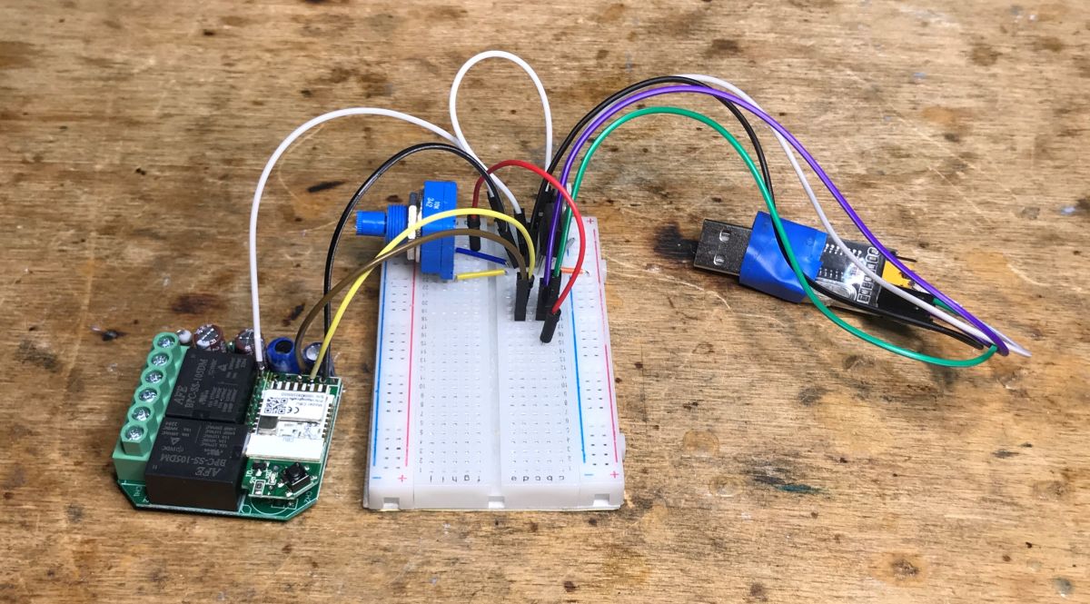
Programming uses RX, TX, 3.3V, and GND with BK7231GUIFlashTool; the article notes boot-order quirks and a CEN reset alternative.
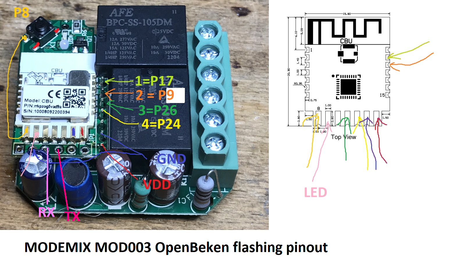
OpenBeken mapping sets P7 as WiFiLED_n, P24 and P26 as toggle channels, P9 and P17 as relays, and P8 as the shared button.
The relay cost PLN 75, shipped with almost nothing extra, and it is judged poor value despite successful 100% local operation.
Generated by the language model.
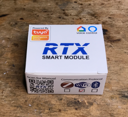
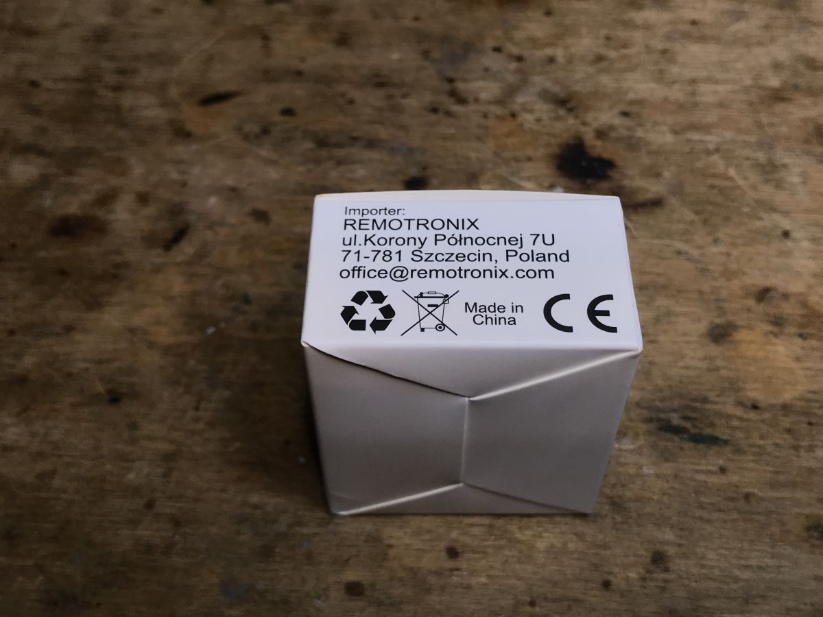
Today we release from the cloud another product that is easy to buy in our country - a double RTX relay compatible with the Tuya application. As a standard, I will show its interior, describe the process of changing the firmware (where to solder the wires, etc.) and then I will give its configuration OpenBeken (which GPIO is the button, which is the LED, etc).
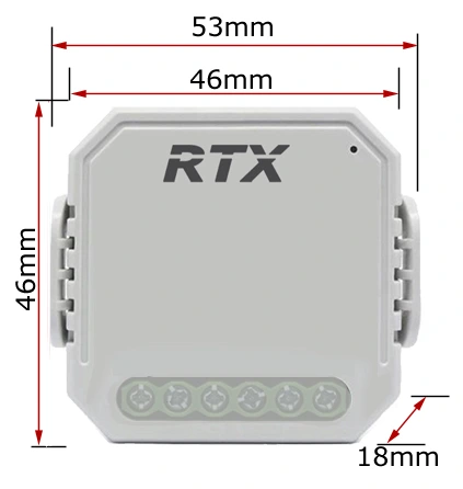
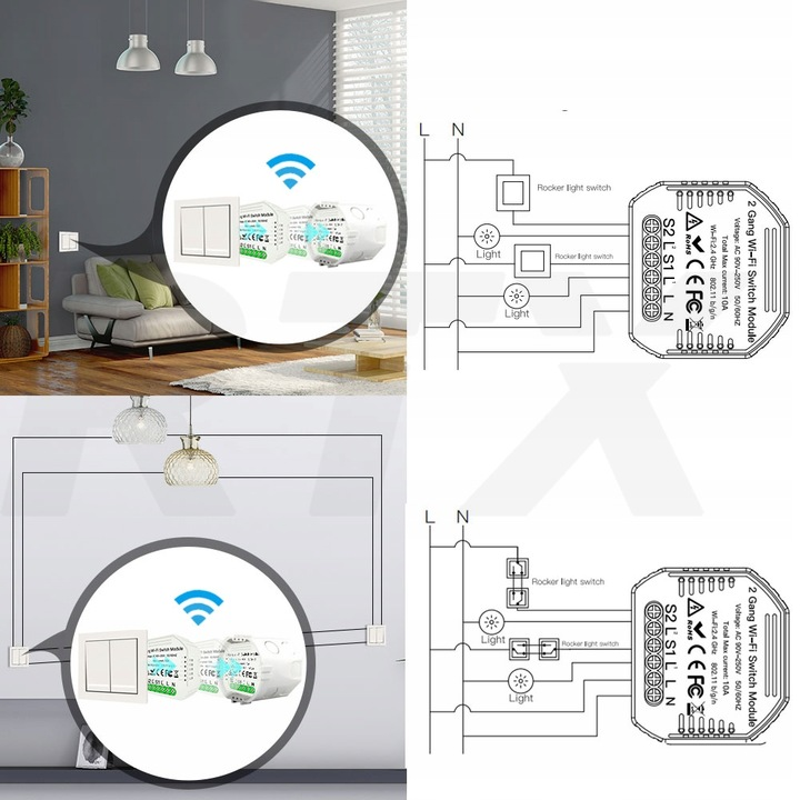
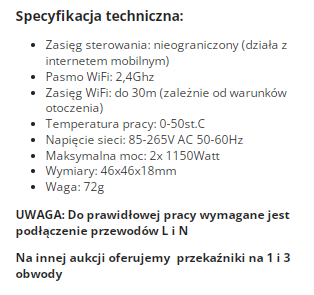
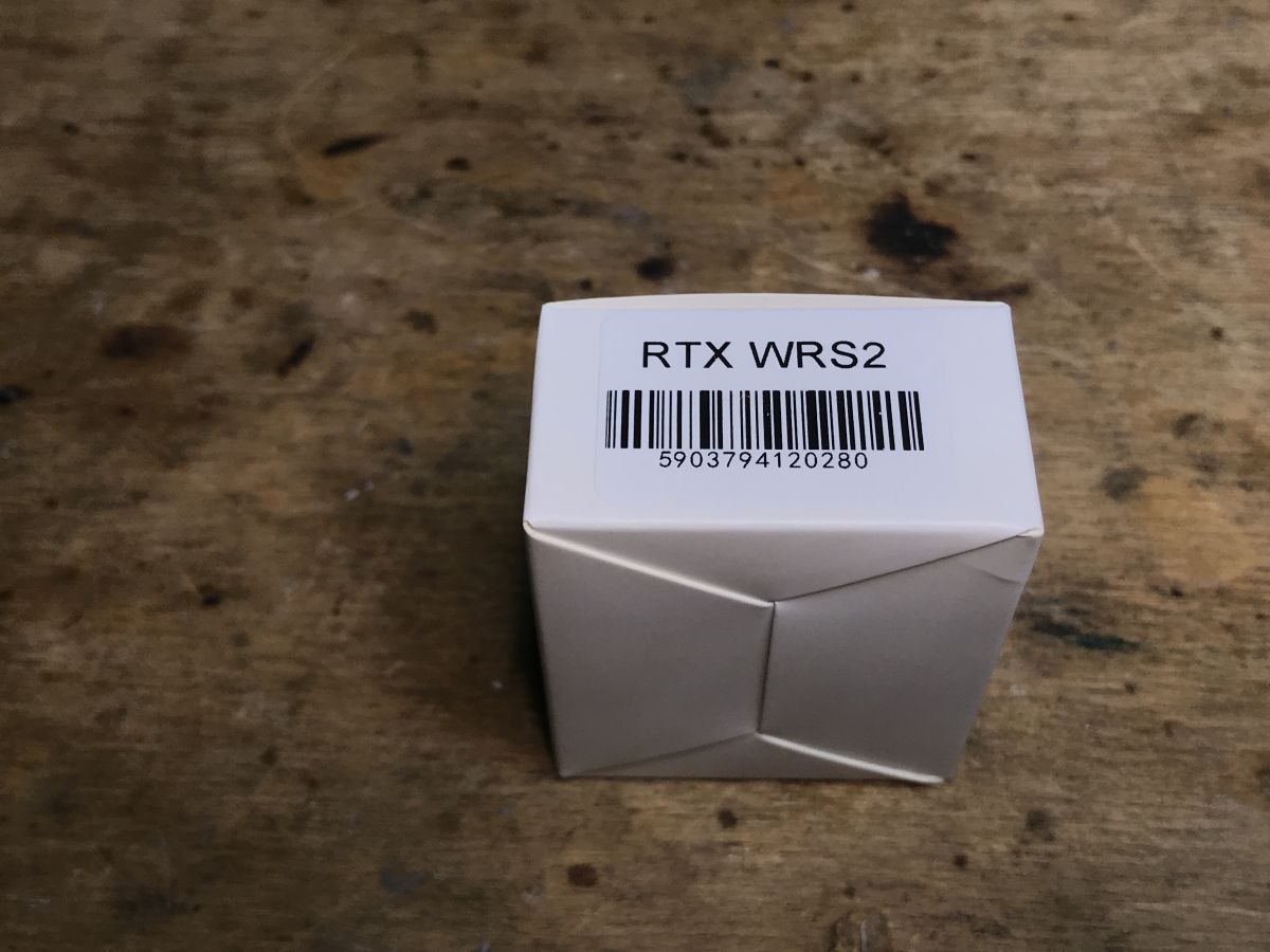
Product purchase One of my readers bought the product on a Polish auction site, and I got it just to upload it to him OpenBeken and then give back to the reader. Thank you! This is always a good opportunity to do a review and analysis. The relay was quite expensive, all PLN 75, but such prices are often as we buy in our country: Dimensions: assembly diagram: Specification: And here I must already pay attention - unlimited range? No, it's just marketing. This device connects to our WiFi network and then the Tuya cloud actually allows you to control it from around the world, but it's different. The annotation "works with mobile internet" is also interesting. Apparently, it is possible to pair this product with a hotspot and any WiFi, also mobile, ... but it does not change the fact that a WiFi router at home is needed to connect this type of Tuya products to the cloud.
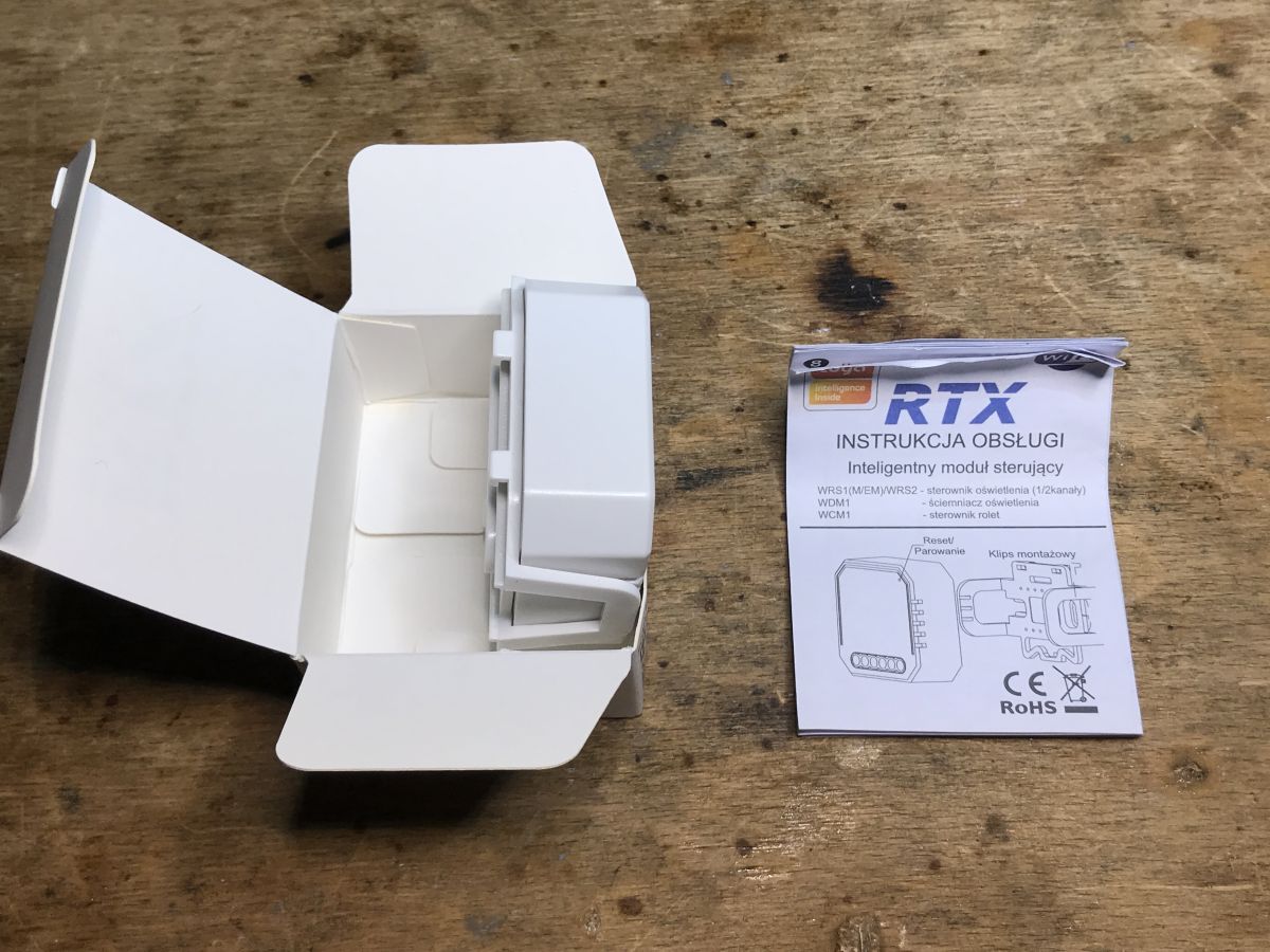
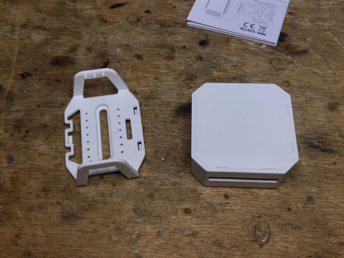
Kit contents Let's see what we get for these PLN 75. This time it's poor... not even screws. The product also does not have "wings" for attaching, although there is this plastic hook.
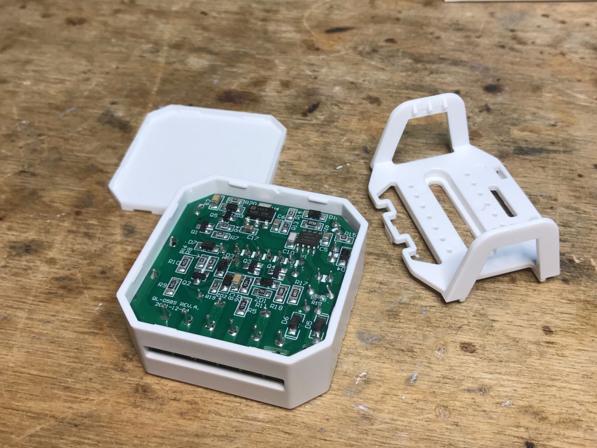
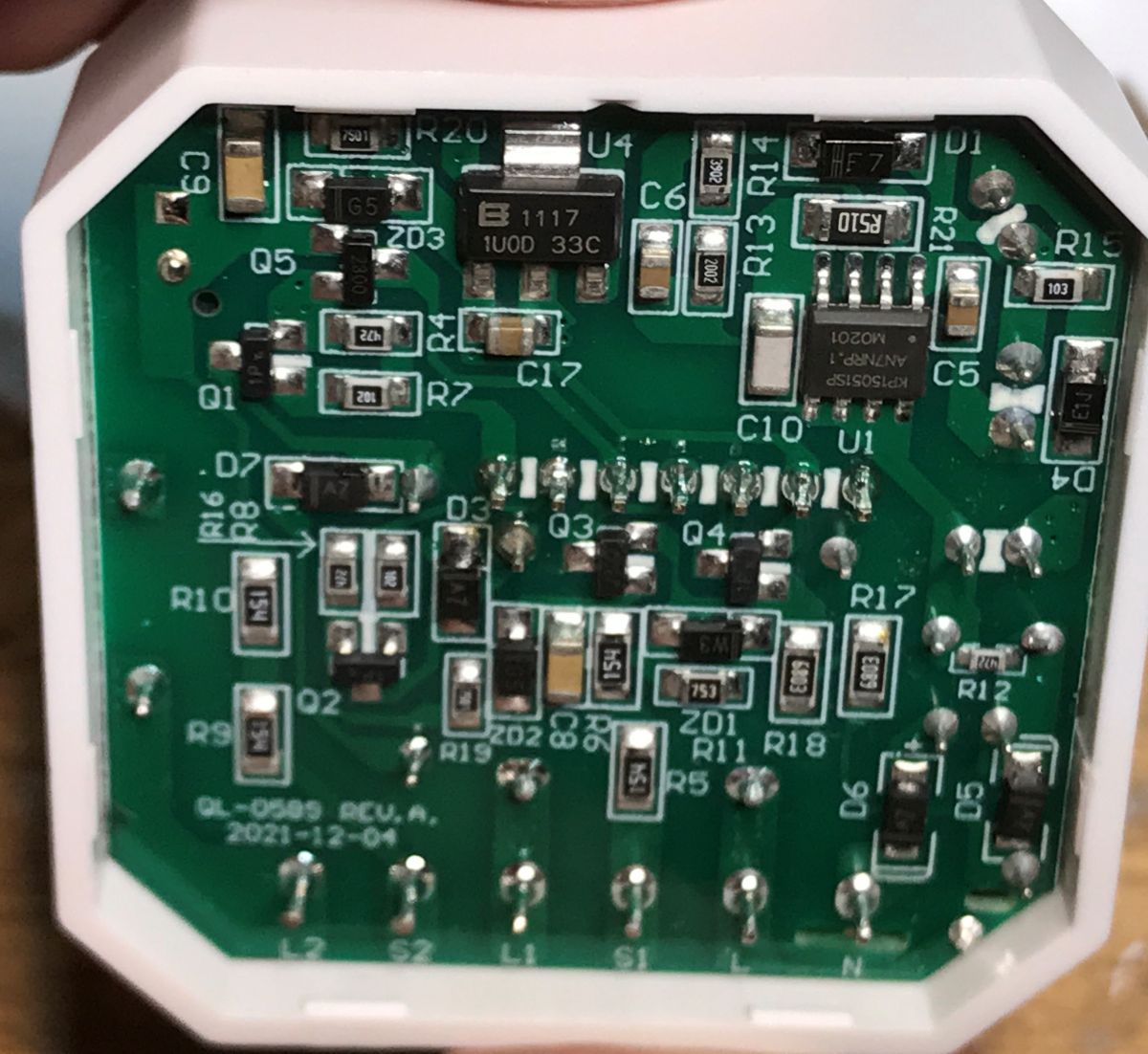
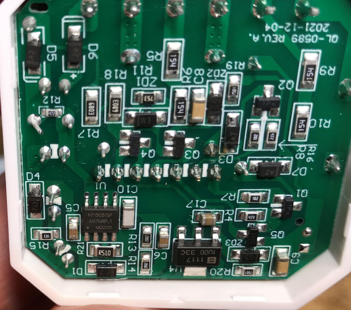
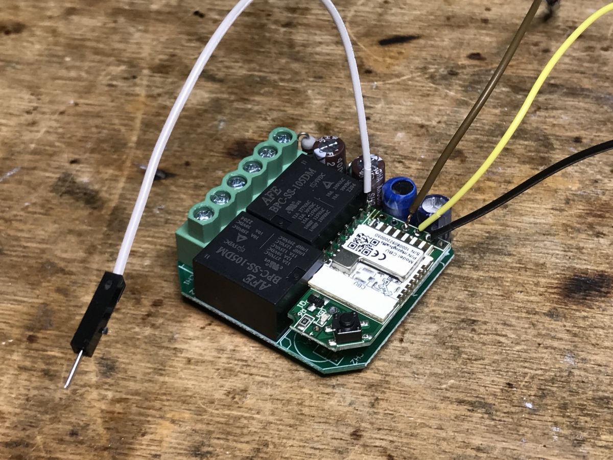
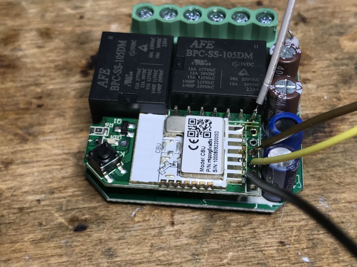
Interior and firmware change The white flap is on the hooks, just pry it with a screwdriver. The system powers the KP15051SP, next to it you can see the AMS1117-3.3V LDO regulator. The top of the PCB, in turn ... I have already described in the case of MOD003. It's identical here. Here is the analysis: There is a module inside CBU, który znajduje się na dodatkowej płytce, na której też jest już jego przycisk (od parowania) oraz dioda LED od stanu WiFi.
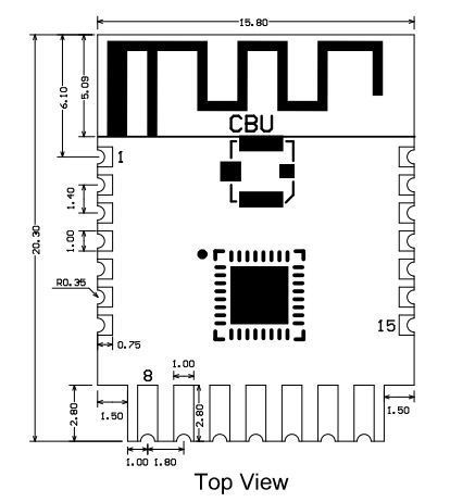
Oto jego wyprowadzenia:
Spoiler:
Pin number
Symbol
I/O type
Function
1
P14
I/O
Common GPIO, which can be reused as SPI_SCK (Correspond to Pin 11 of the IC)
2
P16
I/O
Common GPIO, which can be reused as SPI_MOSI (Correspond to Pin 12 of the IC)
3
P20
I/O
Common GPIO (Correspond to Pin 20 of the IC)
4
P22
I/O
Common GPIO (Correspond to Pin 18 of the IC)
5
ADC
I/O
ADC, which corresponds to P23 on the internal IC (Correspond to Pin 17 of the IC)
6
RX2
I/O
UART_RX2, which corresponds to P1 on the internal IC. (Correspond to Pin 28 of the IC)
7
TX2
I/O
UART_TX2, which is used for outputting logs and corresponds to P0 of the internal IC (Correspond to Pin 29 of the IC)
8
P8
I/O
Support hardware PWM (Correspond to Pin 24 of the IC)
9
P7
I/O
Support hardware PWM (Correspond to Pin 23 of the IC)
10
P6
I/O
Support hardware PWM (Correspond to Pin 22 of the IC)
11
P26
I/O
Support hardware PWM (Correspond to Pin 15 of the IC)
12
P24
I/O
Support hardware PWM (Correspond to Pin 16 of the IC)
13
GND
P
Power supply reference ground
14
3V3
P
Power supply 3V3
15
TX1
I/O
UART_TX1, which is used for transmitting user data and corresponds to Pin 27 of the IC. For the MCU solution, please refer to CBx Module.
16
RX1
I/O
UART_RX1, which is used for receiving user data and corresponds to Pin 26 of the IC. For the MCU solution, please refer to CBx Module.
17
P28
I/O
Common GPIO (Correspond to Pin 10 of the IC)
18
CEN
I/O
Reset pin, low active (internally pulled high), compatible with other modules (Correspond to Pin 21 of the IC)
19
P9
I/O
Common GPIO (Correspond to Pin 25 of the IC)
20
P17
I/O
Common GPIO, which can be reused as SPI_MISO (Correspond to Pin 14 of the IC)
21
P15
I/O
Common GPIO, which can be reused as SPI_CS (Correspond to Pin 13 of the IC)
Test point
CSN
I/O
mode selection pin. If it is connected to the ground before being powered on, enter the firmware test mode. If it is not connected or connected to VCC before being powered on, enter the firmware application mode. Correspond to Pin 19 on the internal IC.
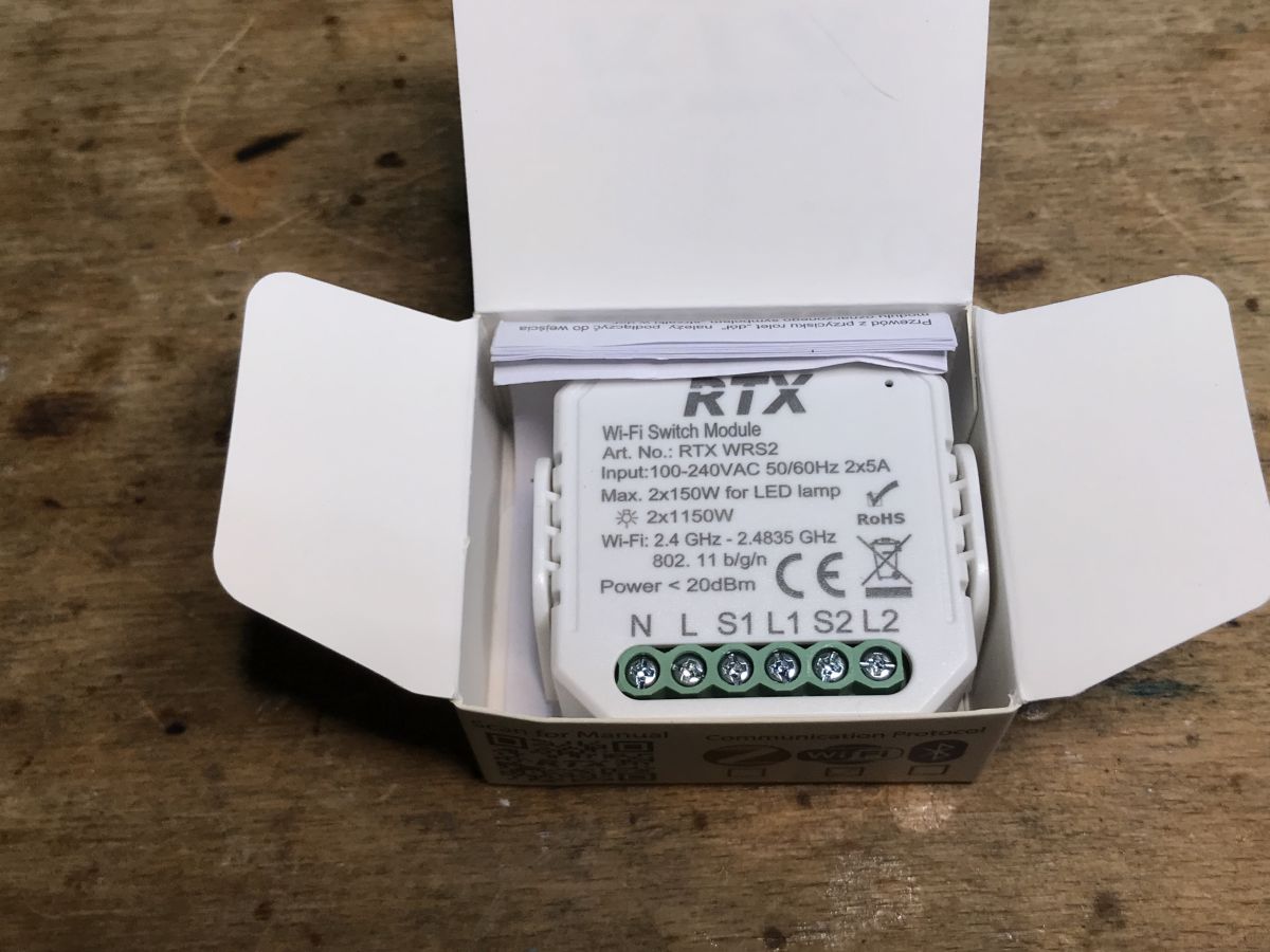
Just solder the wires to: - RX - TX - 3.3V - GND Then you need to use Flasher: https://github.com/openshwprojects/BK7231GUIFlashTool As a rule, a photo from programming: Note - performing a reboot by cutting off the power supply works only when we disconnect the whole thing from the computer with the USB to TTL programmer, and disconnect the 3.3V from the WiFi module. Then connect the USB to the computer, then start the programming/reading procedure in BK Flasher, and then connect the 3.3V pin. It will not work in any other order, nor will it catch if we just disconnect and connect 3.3V with the USB connected all the time. That is my observation. You can also use the CEN reset method instead of power cycle, but I didn't want to solder another wire. And configuration OpenBeken : - P7 - WiFiLED_n - P24 - TglChannelOnToggle - Channel 1 - P26 - TglChannelOnToggle - Channel 2 - P9 - Relay - Channel 1 - P17 - Relay - Channel 2 - P8 - Button - Channel 1 and Channel 2 (set two channels to control one by click and the other by double click) Template:
Code: JSON
Log in, to see the code
Summary This product is almost identical to the MOD003 from Modemix. The same child board from the CBU with additional pads to solder to the RX/TX. Programming went smoothly. Another device can run 100% locally. As for the price, it's not very good. Sometimes it is possible to order a smart switch from China for half that amount, only then we wait much longer for the shipment. For the same amount, you can buy the whole "smart" switch instead of the flush module, which can also be more economical, depending on the intended use. I hope someone may find this information useful. Meanwhile, there are more devices in the queue, LED strips, in which I will also change the batch for another person who does not feel up to the task of working with a soldering iron ...
About Author
p.kaczmarek2 wrote 14606 posts with
rating 12621 , helped 654 times.
Been with us since 2014 year.
TL;DR: The RTX QS-WIFI-S04-2C dual-relay module costs 75 PLN (≈ €16.5) and flashes to OpenBeken in < 2 min; “Programming went smoothly”[Elektroda, p.kaczmarek2, post #20609290] Follow four solder points and correct power-cycle order to avoid boot failure.
Why it matters: A quick firmware swap lets you run the device 100 % locally, cloud-free.
It is a compact, two-gang Wi-Fi relay module that fits behind a wall switch and links to Tuya or custom firmware. The board carries a BK7231N SoC on a CBU module and drives two mechanical relays [Elektroda, p.kaczmarek2, post #20609290]
Ground the CSN test pad before power-up or perform a precise 3.3 V power-cycle while USB remains disconnected to trigger the bootloader [Elektroda, p.kaczmarek2, post #20609290]
What GPIO pins map to relays, button and LED in OpenBeken?
The bootloader won’t respond if you only reconnect 3.3 V while USB stays powered. Disconnect USB first, then reconnect it after the device is unpowered—a frequent failure case [Elektroda, p.kaczmarek2, post #20609290]
How does this module compare to the MOD003?
Hardware is almost identical; both reuse the same CBU daughter-board. Performance and pinout match, so existing MOD003 OpenBeken templates work here [Elektroda, p.kaczmarek2, post #20609290]
Is the marketing claim of “unlimited range” accurate?
No. The module’s range is limited to your Wi-Fi network; remote control only works via the internet once the router is connected to Tuya or another server [Elektroda, p.kaczmarek2, post #20609290]
What current can each relay switch?
Typical 10 A at 250 VAC is printed on the relay can; always derate by 20 % for inductive loads [Relay Datasheet, 2023].
Can I solder the pads without fully removing the PCB?
What happens if I leave USB connected while power-cycling 3.3 V?
The bootloader stays in application mode, and the flash tool reports “sync failed.” Disconnecting USB first resolves the issue [Elektroda, p.kaczmarek2, post #20609290]


Comments