WXDM2 dual dimmer teardown and OpenBeken port analysis reveals an LMB54 BK7231N Wi‑Fi module plus two HC32F003 microcontrollers.
The Wi‑Fi module only transmits over a unidirectional UART, and each HC32F003 selects commands by 0x01 or 0x02.
A working control frame is `uartSendHex 0A FF 55 02 00 9F 00 00 0A`, with 9F acting as a 0–255 brightness value.
OpenBeken scripts can drive the dimmer from the web panel using `OnChannelChange`, and the proof-of-concept loop works.
State memory is still missing, so switching the lamp off currently means setting the dimmer to zero.
I will present here an analysis of the interior and a short reverse engineering of the UART protocol of another Tuya dimmer, this time based on a rather unusual LMB54 (BK7231N) module and two HC32F003 microcontrollers. I will fully describe here how it can be programmed and added its OpenBeken support using the scripting language offered by these firmwares. The presented dimmer will be quite unusual, because it does not use the TuyaMCU protocol as discussed products before , only from a slightly different, simpler UART communication, which in this case is unidirectional.
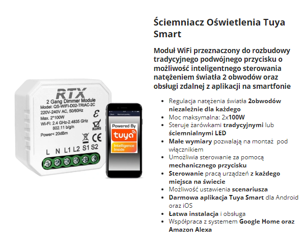
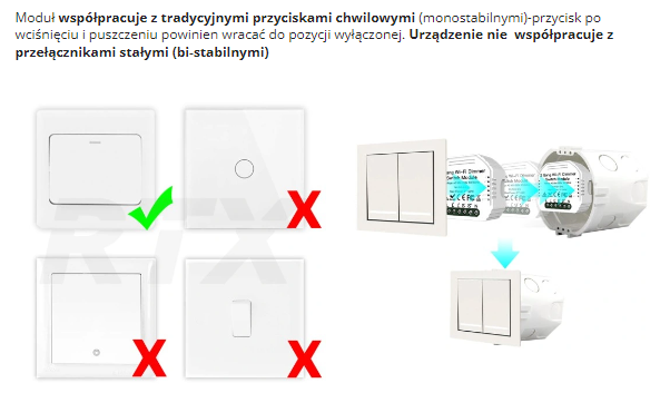
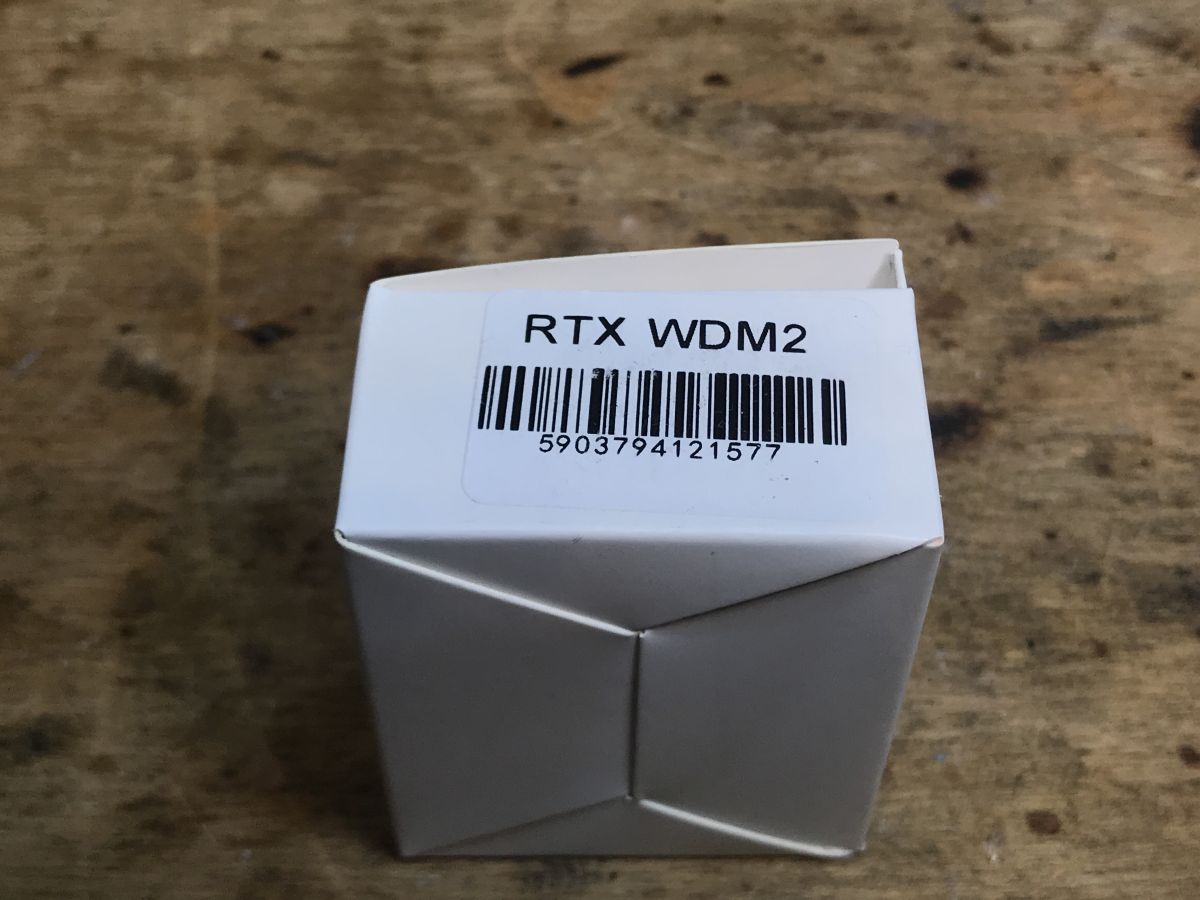
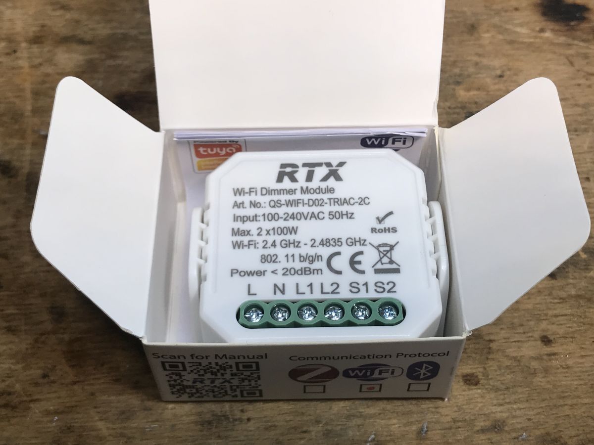
Purchase WXDM2 The dimmer gave me a reader (along with a set of other gadgets) to upload OpenBeken to them, as I wrote in the previous part. The purchase of the dimmer itself took place on the Polish auction site: The dimmer cost PLN 80, which is quite a lot, but at least it supports two light bulbs and two switches. Description from seller: Important note - in the original firmware it dims by pressing the button, so the monostable button is preferred: assembly diagram: But beware, the product shipped has the N and L places swapped, you should follow the markings on its housing, they have the "last word"
Received set This seller doesn't even provide mounting screws or tape in the kit...
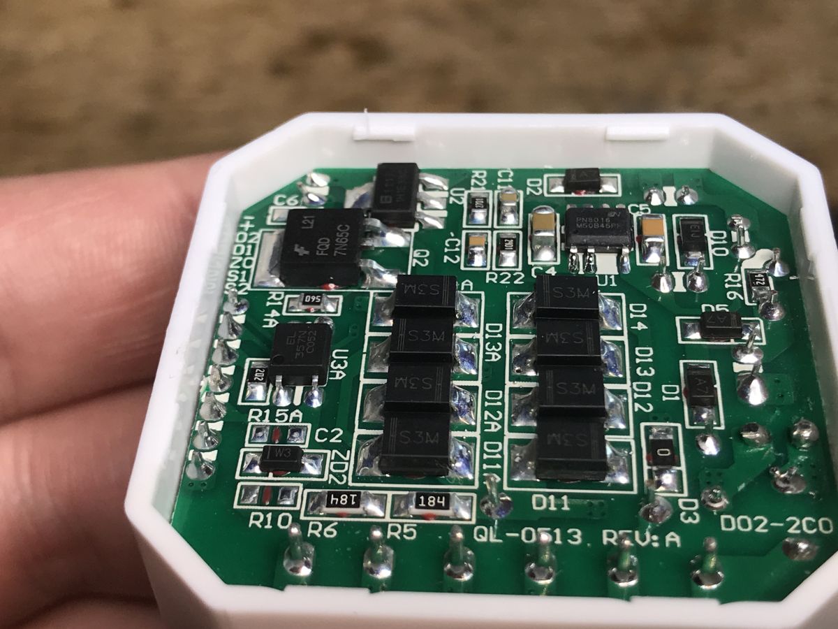
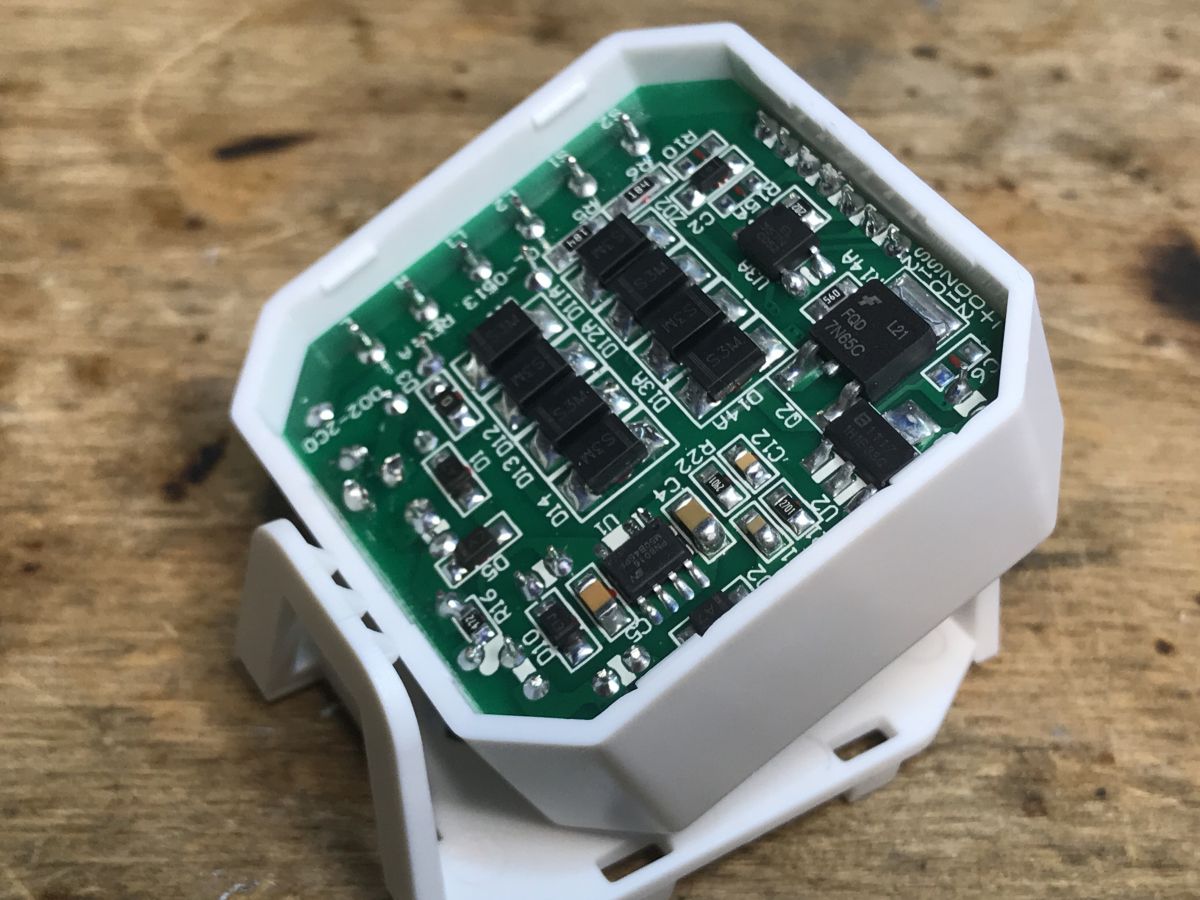
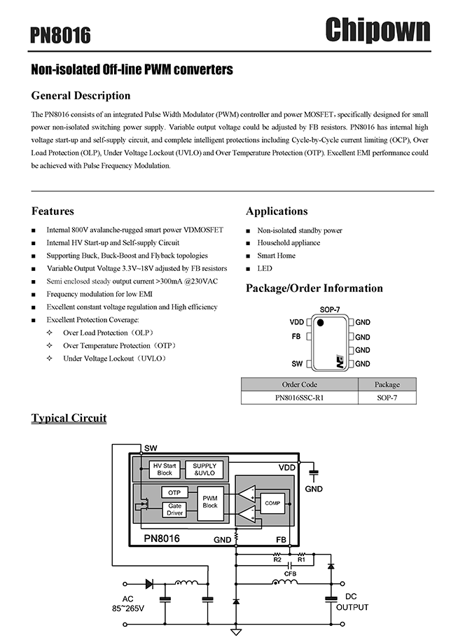
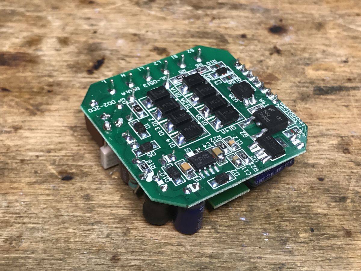
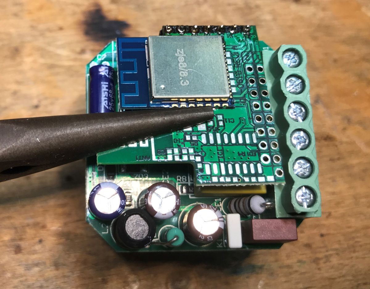
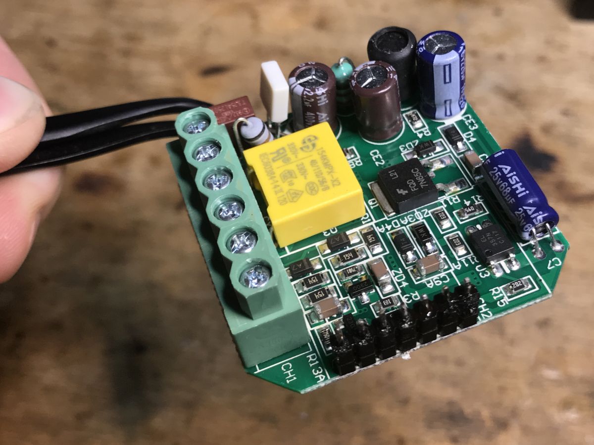
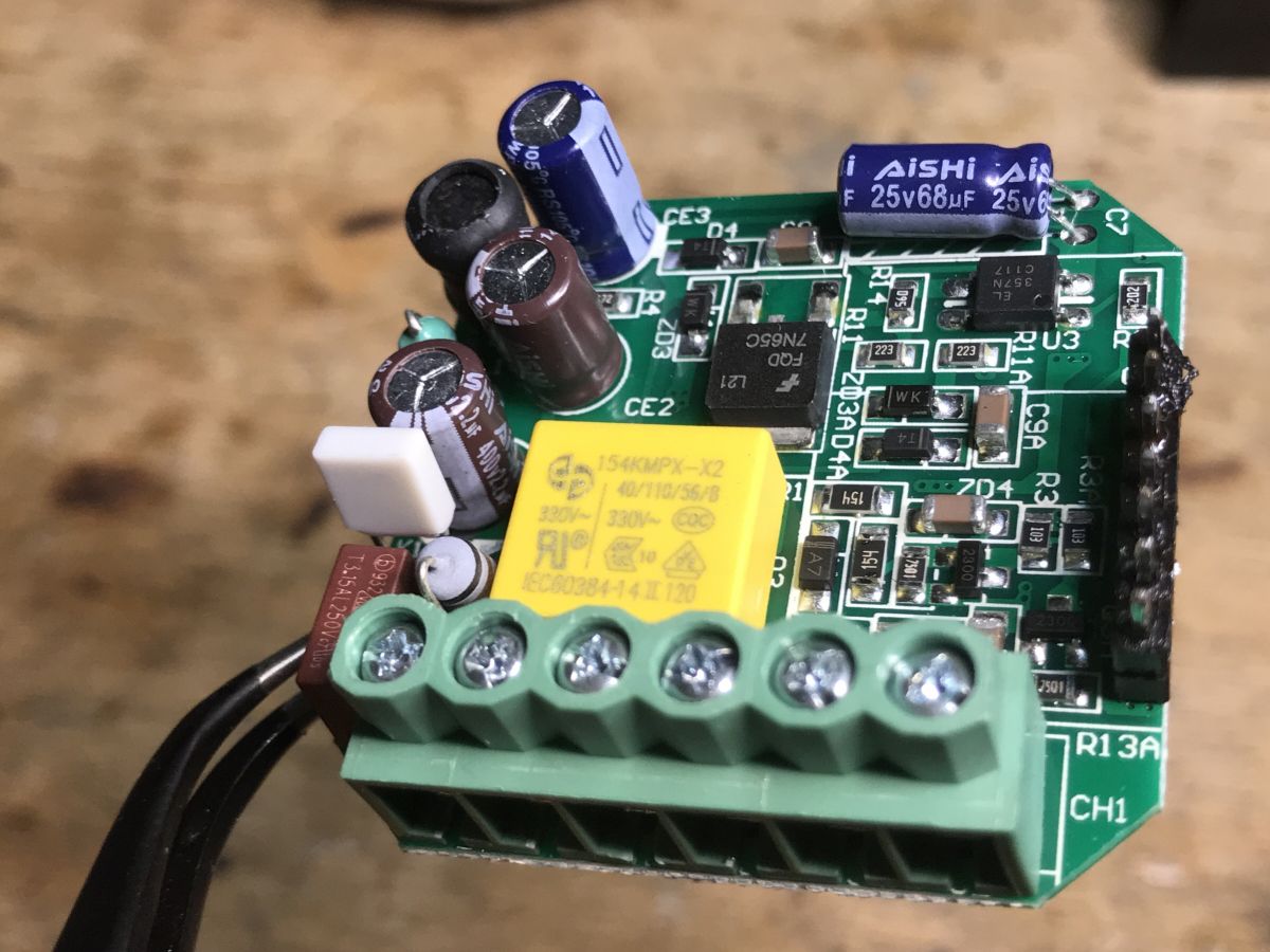
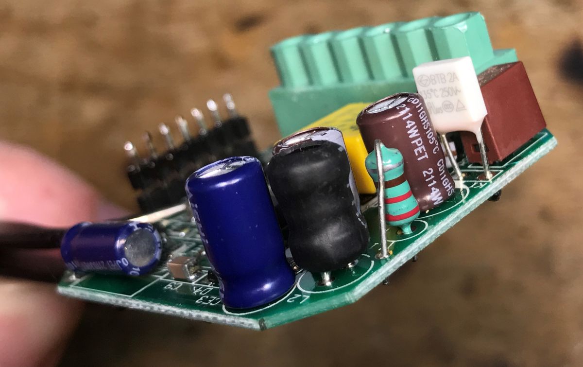
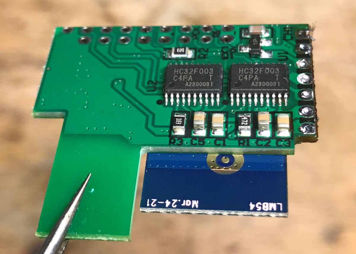
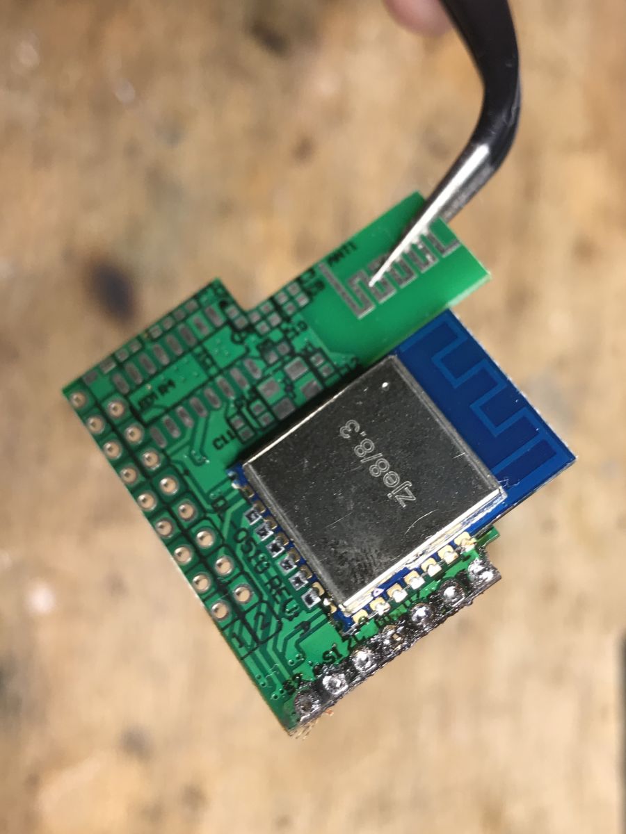
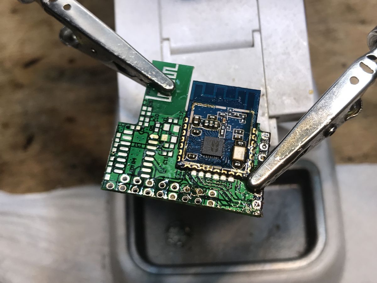
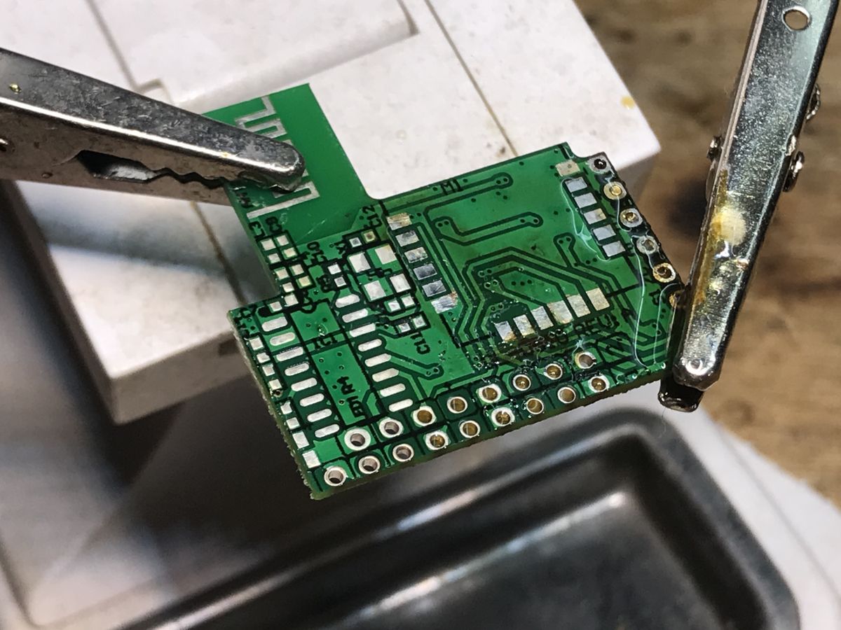
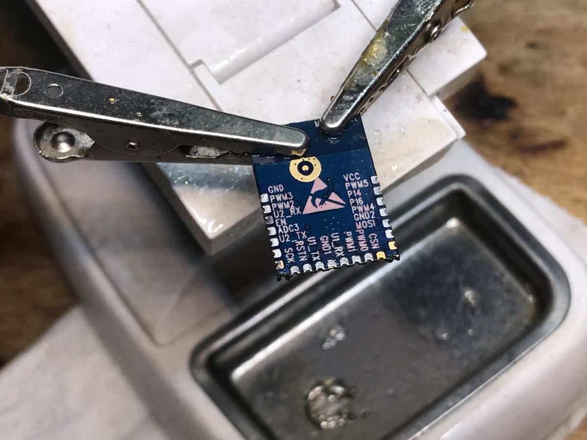
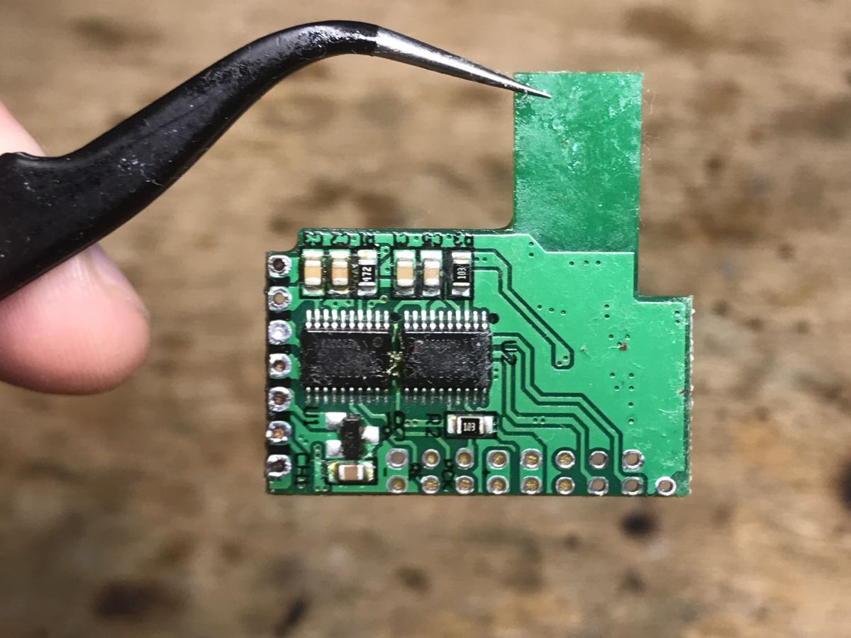
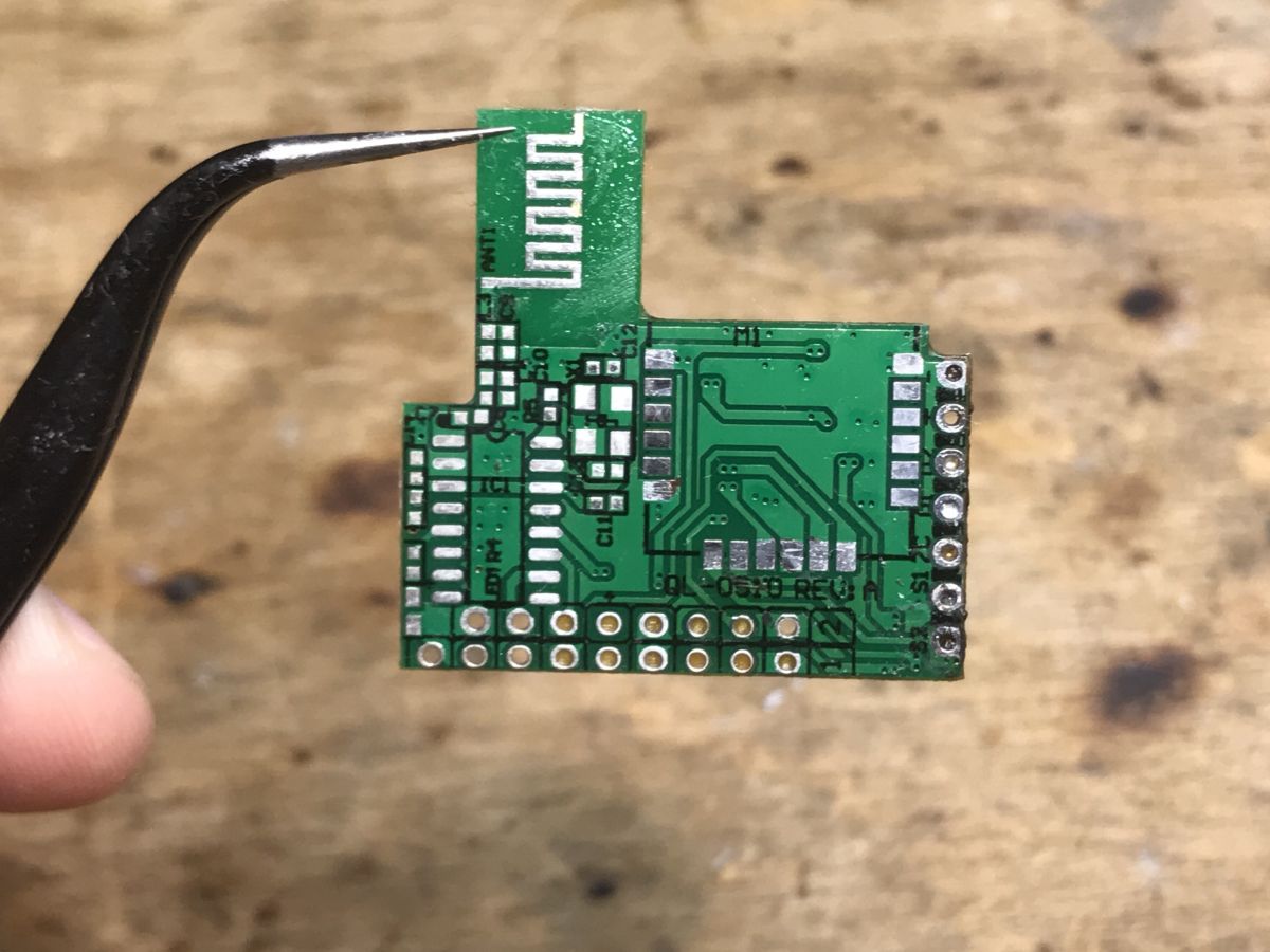
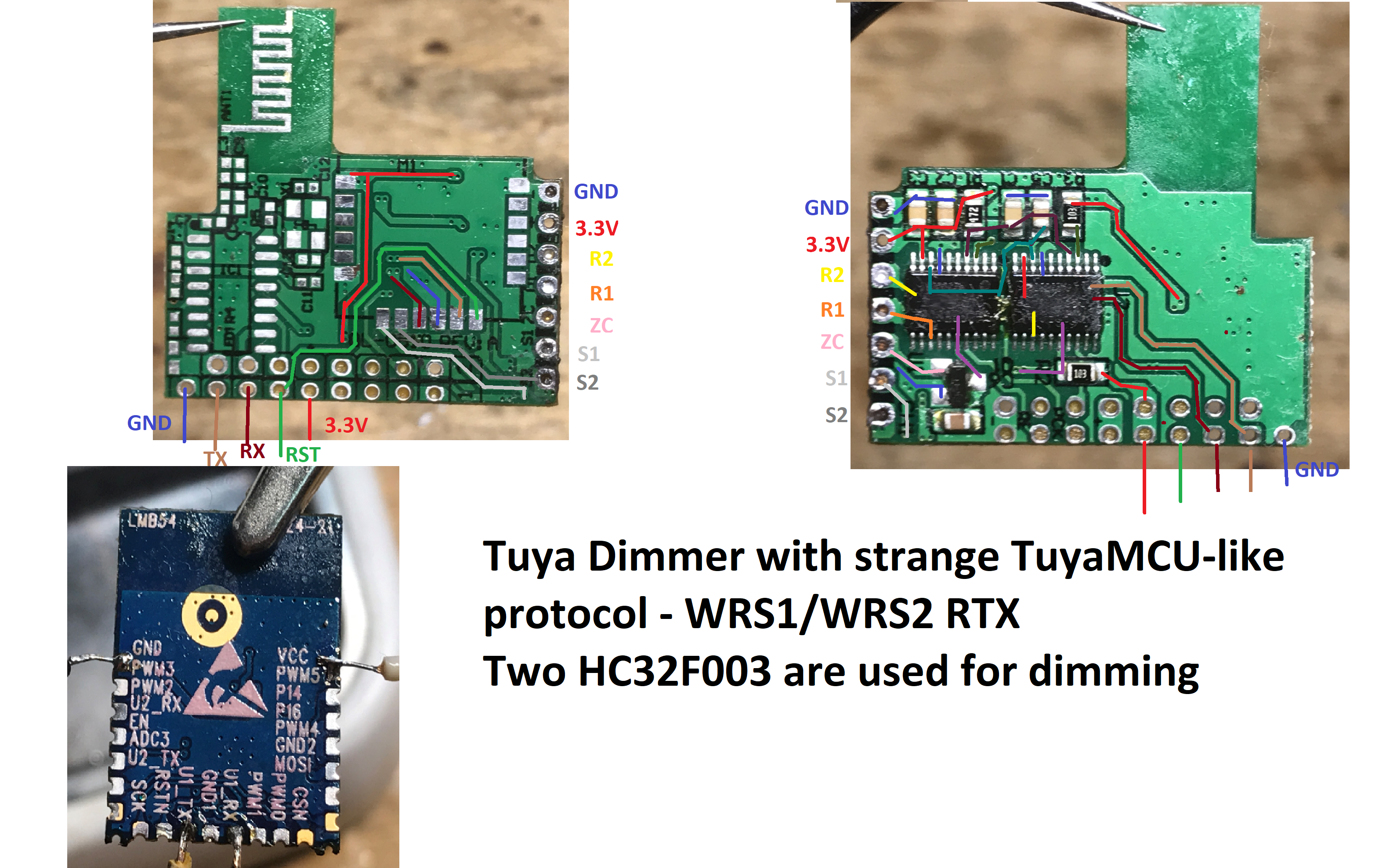
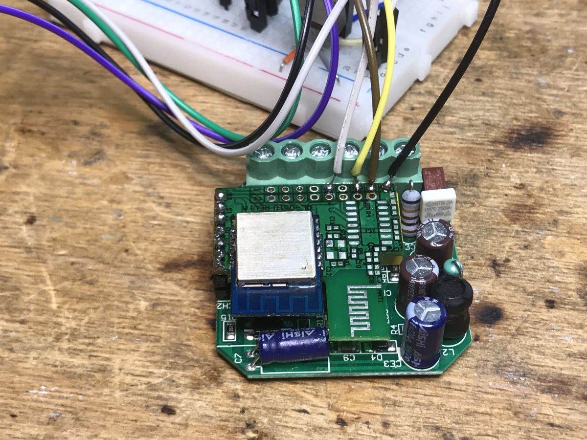
WXDM2 interior, module pins and PCB analysis Just pry the cover: The parts of the dimmer I analyzed. Here you can see a 3.3V LDO regulator, an optocoupler, a MOSFET (7N65C), 8 S3M diodes and a PN8016 converter controller. We look further - the WiFi module is not signed, it is not WB3S: Let's desolder the upper PCB: Here is the second MOSFET, 7N65C... and a large capacitor, but I haven't analyzed its role. On the bottom of the PCB with the WiFi module, there are up to two HC32F003 microcontrollers - could it be a product from TuyaMCU? But how is it two? One per dimming channel? Now you need to unsolder the screen from the WiFi module to see what's inside. BK7231N! There are chances to change the firmware. But where is the RX and TX? Let's desolder the WiFi module to check its pinout description. Hot air is essential here.
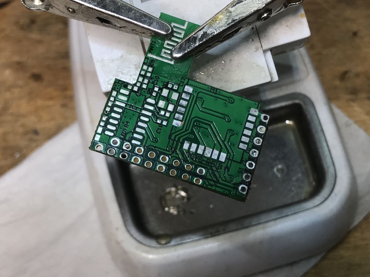
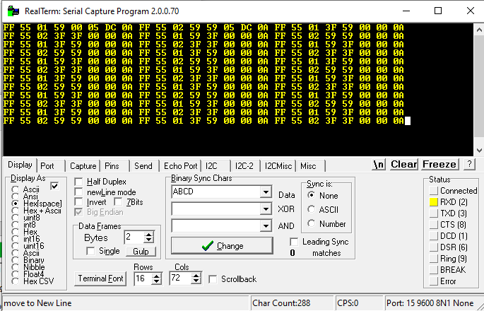
Finally, I developed a sketch: Explains: - 3.3V and GND is known, power supply - S1 and S2 are button inputs, they are connected to the WiFi module - RX and TX from the WiFi module is led outside - TX from WiFi module goes to both HC32F003 - R1 and R2 are dimmer outputs, each supports one HC32F003 - ZC is zero detection so that the dimmer knows when to start conducting (it is connected through a transistor, to both HC) I also tried eavesdropping on UART communication. Only on the TX from the WiFi system something is happening. Collected data as text:
Byte 0x55 looks like TuyaMCU protocol, but TuyaMCU is not. 0x01 and 0x02 look like identifiers which dimmer we are setting. I decided to upload OpenBeken and check if I am able to send the UART packet controlling the dimmer myself.
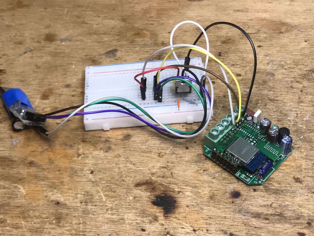
Uploading the firmware and the first tests of control However, it quickly turned out that all the fun with the soldering was unnecessary - in fact, only the WiFI module "talks" to the UART here, so it can be programmed in the system. Nothing will disturb us in the MCU. I marked the pads in the previous paragraph. Here is the connection of the programmer: I uploaded the batch via: https://github.com/openshwprojects/BK7231GUIFlashTool according to the instructions on the page above. then in OpenBeken I used the uartSendHex command to test sending various packets to the dimmers. I wanted to simulate the operation of the original firmware. This is necessary to control these dimmers. After some testing, I've come to the conclusion that the following package works:
And 9F is the brightness level value, from 0 to 255, one byte. There is no checksum here. I don't know what the rest of the bytes are, except for 0x02 which is the ID of which of the two dimmers on board we are controlling.
Proof of concept - test script I already have a suspicion of how it works. So I can prepare a simple OpenBeken script that changes the brightness of the lamp in a loop. Will the script work as expected?
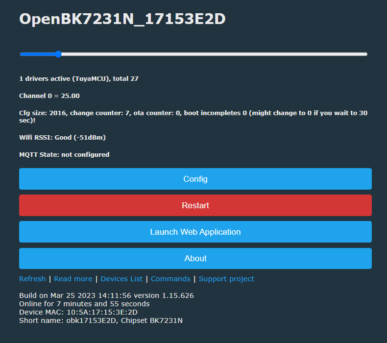
The final example - the bar and mapping its changes to the UART value OpenBeken offers the ability to set the type of channels, i.e. the way they are displayed. The Dimmer256 type is a dimmer strip with a range of 0 to 255, so it's as found here. In combination with the script below, we can get the dimmer control on the web panel:
When channel 0 is changed, a given message will be sent to the UART. This is enough to have real control over this dimmer.. Result:
Summary It was quite an unusual product. I have not met a dimmer from Tuya before, but without TuyaMCU, using instead a simplified, "one-way" UART protocol (i.e. here only the WiFi module sends information, it does not receive anything). This "unidirectionality" is a bit justified for me, however, because there are separate MCUs inside to dim each channel. Both are connected to one TX1 line from BK7231N and they only select packets intended for them by their content (one of the bytes is 0x01 or 0x02). The dimmer is already working in OpenBeken, although it could be improved a bit and, for example, remembering the dimmer state (at the moment there is only one variable, so turning off the lamp is equivalent to setting the dimmer to 0). All this is possible to do by OBK scripts, so I consider the dimmer to be anyway supported and in the future I will give a separate topic about the already mentioned scripts.
About Author
p.kaczmarek2 wrote 14649 posts with
rating 12661 , helped 655 times.
Been with us since 2014 year.
Hello.
A very interesting article.
A shortened datasheet of the above-mentioned wifi module is available on the web, which I allowed myself to attach.
Kind regards. [Read more]
pedropaislopes
29 Jun 2023 19:38
Hi! This is my first post, so please be easy with me...
I have a similar module. I've purchased it on an online store in my country (Brazil) for around 20 US dollars. It uses Tuya smart APP and has... [Read more]
p.kaczmarek2
29 Jun 2023 19:54
Thank you for a deeper insight into this device. I was not aware about the smooth transition ramp data included in the UART packets.
The 0a ff 55 seems to me just like a header "magic" constant, which... [Read more]
ferbulous
04 Aug 2023 10:14
Hi, how do you press the button on momentary switch if you need to dim or increase the brightness?
Does each long press just switch to dimming and the reverse? [Read more]
p.kaczmarek2
04 Aug 2023 10:43
Hello @ferbulous , it's been a long time since I've handled that device (I was doing it for our reader) and I no longer have access to it, I'll forward your question, but as far as I remember, the button... [Read more]
ferbulous
04 Aug 2023 11:08
Yes, I just don't quite understand how to use it with momentary switch.
Indeed, but which action increase or decrease the brightness if you recall
I have the usual smart dimmer with knobs to adjust... [Read more]
p.kaczmarek2
30 Dec 2024 23:18
It seems we have user with the same device in another topic. I'm linking to his post now, see:
https://www.elektroda.com/rtvforum/viewtopic.php?p=21369813#21369813
(post #15, 30 Dec 2024 22:23 by @danielberglund1977... [Read more]
mortadella16
11 Oct 2025 01:48
I just confirmed that the proposed config template and autoexec.bat work with the single-channel dimmer from Aliexpress. The module is CB3S Rev. C.
I removed the second channel from the configuration/autoexec... [Read more]
FAQ
TL;DR: This FAQ gives OpenBeken users 15 practical answers for WXDM2 dual dimmers; the core finding is “one-way UART”: brightness uses 0A FF 55 … 0A, not full TuyaMCU, solving BK7231N/CB3S flashing, scripting, switch dimming, and Home Assistant MQTT setup. [#20631683]
Why it matters: WXDM2-style dimmers can be taken off the Tuya cloud while keeping two independent 0–255 dimmer channels.
Alternative
WiFi module
Dimmer MCU layout
Protocol finding
Practical change
WXDM2 unit
LMB54 with BK7231N
2 × HC32F003
TX-only UART
Use OpenBeken uartSendHex scripts
Similar Brazilian unit
CB3S
1 × HK32F030MF4P6
9600 8N1 TX-only UART
Same packet idea, clearer L1/L2 bytes
Single-channel AliExpress unit
CB3S Rev. C
1 channel
Same template adapted
Remove L2 logic
Key insight: The WiFi module only transmits dimming commands. Each dimmer controller selects packets by the 01 or 02 channel byte, so OpenBeken can replace the original firmware with scripts.
Quick Facts
WXDM2 cost 80 PLN, supports 2 bulbs and 2 switches, and originally dims by holding a momentary button. [#20631683]
The PCB analysis found 3.3 V logic power, BK7231N, 2 × HC32F003, 2 × 7N65C MOSFETs, 8 × S3M diodes, and a PN8016 converter controller. [#20631683]
The working OpenBeken brightness range is 0–255, matching the Dimmer256 channel type and the one-byte brightness field. [#20631683]
The reported Home Assistant setup used MQTT client topic DM02, qos: 1, retained messages, and brightness state from channel 11. [#20635703]
How do you flash OpenBeken onto a WXDM2 dual dimmer with a BK7231N or CB3S WiFi module?
Flash OpenBeken through the WiFi module UART pads, using BK7231GUIFlashTool for BK7231N or CB3S devices.
Open the dimmer and identify 3.3 V, GND, RX, and TX.
Connect a UART programmer to the exposed pads.
Flash OpenBeken, then test dimming with uartSendHex.
The author found desoldering was unnecessary because only the WiFi module talks on UART. Do not power the mains side while using a low-voltage programmer. [#20631683]
What UART packet format controls brightness on the WXDM2 dual dimmer using OpenBeken?
The brightness packet uses a Tuya-style header, a channel byte, one or two brightness bytes, ramp bytes, and final 0A. The CB3S variant used 0A FF 55 01_or_02 L1brightness L2brightness Dimmer_ramp Dimmer_ramp 0A at 9600 8N1. Brightness runs from 00 to FF, so OpenBeken maps it cleanly to 0–255. For the WXDM2 test, uartSendHex 0A FF 55 02 00 9F 00 00 0A controlled channel 2. [#20635703]
How can I configure OpenBeken autoexec.bat to control both L1 and L2 dimmer channels independently?
Use separate OpenBeken Dimmer256 channels and separate OnChannelChange handlers for L1 and L2. One working setup used channel 11 for L1 and channel 12 for L2. It sent 0A FF 55 01 $CH11$ 00 05 DC 0A for L1. It sent 0A FF 55 02 00 $CH12$ 05 DC 0A for L2. Auxiliary channels 21 and 22 stored long-press direction. This keeps both outputs independent in OpenBeken and MQTT. [#20635703]
What does the UART command `0A FF 55 02 00 9F 00 00 0A` mean on a Tuya-style dual dimmer?
The command sets dimmer channel 02 to brightness 9F, which is 159 on a 0–255 scale. 0A FF 55 acts as a fixed header. 02 selects the second dimmer. 00 9F maps channel values, with 9F used as the active brightness byte in the author’s test. 00 00 gives an immediate transition instead of the smoother 05 DC ramp. The final 0A terminates the packet, not a confirmed checksum. [#20631683]
How do momentary wall switches control brightness increase and decrease on the WXDM2 or similar Tuya dimmer?
A momentary switch toggles on short press and changes brightness while held. In the shared OpenBeken script, a click on pin 8 toggles L1 between 0 and 255. Holding the switch changes brightness by 15 steps per event. A helper channel stores direction as 1 or -1. On release, the script reverses that direction, so the next hold dims the other way. The same logic applies to S2 on pin 9. [#20635703]
What is the purpose of the `05 DC` ramp bytes in the WXDM2 dimmer UART protocol?
The 05 DC bytes define a smooth brightness ramp of about half a second on the tested CB3S dimmer. Replacing both ramp bytes with 00 00 produced an immediate brightness change. The tester could not change L1 and L2 ramp behavior independently. That means the ramp likely applies globally inside the dimmer MCU for each received command. [#20635703]
What is TuyaMCU, and how is this WXDM2 dimmer protocol different from the normal TuyaMCU protocol?
“TuyaMCU is a serial device-control protocol that lets a Tuya WiFi module exchange structured commands with a separate MCU, usually using bidirectional UART frames and defined datapoints.” This WXDM2 protocol differs because the analyzed unit used only TX from the WiFi module. The dimmer MCUs did not send data back. The author saw Tuya-like bytes FF 55, but concluded it was not normal TuyaMCU. There was also no confirmed checksum. [#20631683]
What is OpenBeken, and why is it useful for replacing Tuya cloud firmware on BK7231N and CB3S devices?
“OpenBeken is open firmware for Beken-based smart devices that provides local control, scripting, MQTT integration, and Tuya-firmware replacement without cloud dependency.” It helped here because BK7231N and CB3S modules could send custom UART bytes with uartSendHex. OpenBeken channels also expose 0–255 dimmer controls. One user reported that after converting this dimmer, Tuya integration was officially switched off in Home Assistant. [#20635703]
BK7231N vs CB3S dimmer modules — what changes when reverse engineering and flashing OpenBeken?
BK7231N and CB3S both work with OpenBeken, but their boards expose different module layouts and MCU arrangements. The WXDM2 used an LMB54 module with BK7231N and 2 × HC32F003 controllers. The similar Brazilian dimmer used CB3S and 1 × HK32F030MF4P6 controller. Reverse engineering therefore focuses on finding each board’s UART pads and button pins. The dimming packet concept stayed the same: TX-only control with 01 and 02 channel selection. [#20635703]
How can I use Home Assistant MQTT with an OpenBeken-flashed dual dimmer?
Configure Home Assistant MQTT lights against OpenBeken channel topics. The shared example used MQTT client topic DM02. L1 state came from DM02/11/get, and commands went to DM02/11/set. The YAML used schema: template, qos: 1, retain: true, and optimistic: false. It mapped brightness 0 to off and nonzero values to on. For L2, repeat the pattern with channel 12. [#20635703]
Which pins on the WXDM2 or CB3S dimmer are used for UART flashing, TX dimmer control, and S1/S2 button inputs?
The key pins are 3.3 V, GND, RX, TX, S1, S2, dimmer outputs, and zero-cross detection. On the WXDM2, TX from the WiFi module goes to both HC32F003 dimmer controllers. S1 and S2 connect to the WiFi module. R1 and R2 drive the dimmer outputs. ZC carries zero-cross detection through a transistor to both dimmer controllers. In the CB3S OpenBeken script, S1 used pin 8 and S2 used pin 9. [#20631683]
Why does the WXDM2 dual dimmer use one-way UART communication from the WiFi module to HC32F003 or HK32F030 microcontrollers?
The design uses one-way UART because the dimmer MCUs only need brightness commands from the WiFi module. In the WXDM2, both HC32F003 controllers share one TX line from the BK7231N module. Each controller filters packets by channel byte, 01 or 02. The WiFi module does not need return status for basic dimming. This simplifies the protocol, but it also removes feedback and error reporting. [#20631683]
How can I add long-press dimming behavior for S1 and S2 buttons in OpenBeken scripts?
Add click, hold, release, and channel-change handlers for each switch. For L1, the shared script used OnClick 8 to toggle channel 11 between 0 and 255. It used OnHold 8 to add or subtract 15 brightness points. It used channel 21 as the direction variable. OnRelease 8 flipped that variable. L2 repeated the same pattern on pin 9, channel 12, and direction channel 22. [#20635703]
What safety issues should I check before wiring a WXDM2 dimmer, especially if the seller diagram swaps N and L?
Check the markings on the dimmer housing before wiring live and neutral. The seller diagram showed N and L reversed for the shipped product. The author warned that the housing markings have the “last word.” This is a mains-voltage dimmer, and S1/S2 in the similar module connect to AC voltage. Do not trust only the auction diagram. Verify L, N, load outputs, and switch inputs before energizing the circuit. [#20631683]
Can the OpenBeken configuration from a dual-channel Tuya dimmer be adapted for a single-channel AliExpress CB3S dimmer?
Yes, remove the second channel logic and keep the matching single-channel UART command. A later tester confirmed the proposed template and autoexec.bat worked on a single-channel AliExpress dimmer with CB3S Rev. C. They removed L2 configuration because the device had only one dimmer output. This is the main edge case: dual-channel scripts will reference missing channels unless you delete the unused L2 handlers. [#21716540]


Comments
Hello. A very interesting article. A shortened datasheet of the above-mentioned wifi module is available on the web, which I allowed myself to attach. Kind regards. [Read more]
Hi! This is my first post, so please be easy with me... I have a similar module. I've purchased it on an online store in my country (Brazil) for around 20 US dollars. It uses Tuya smart APP and has... [Read more]
Thank you for a deeper insight into this device. I was not aware about the smooth transition ramp data included in the UART packets. The 0a ff 55 seems to me just like a header "magic" constant, which... [Read more]
Hi, how do you press the button on momentary switch if you need to dim or increase the brightness? Does each long press just switch to dimming and the reverse? [Read more]
Hello @ferbulous , it's been a long time since I've handled that device (I was doing it for our reader) and I no longer have access to it, I'll forward your question, but as far as I remember, the button... [Read more]
Yes, I just don't quite understand how to use it with momentary switch. Indeed, but which action increase or decrease the brightness if you recall I have the usual smart dimmer with knobs to adjust... [Read more]
It seems we have user with the same device in another topic. I'm linking to his post now, see: https://www.elektroda.com/rtvforum/viewtopic.php?p=21369813#21369813 (post #15, 30 Dec 2024 22:23 by @danielberglund1977... [Read more]
I just confirmed that the proposed config template and autoexec.bat work with the single-channel dimmer from Aliexpress. The module is CB3S Rev. C. I removed the second channel from the configuration/autoexec... [Read more]