logo elektroda
logo elektroda
X
logo elektroda

[CB2S/BK7231N] TuyaMCU Elegrp DPR10 Smart Dimmer Switch Teardown: Tuya, OpenBeken

efirestone 3108 8
ADVERTISEMENT
  • Helpful post
    #1 20559665
    efirestone
    Level 1  
    This is a tear down of the ELEGRP Smart Dimmer DPR10, which is a dimmer switch with a slick touch-sensitive dimmer strip. It can be connected to the ELEGRP app, or to Tuya Smart Life app. The chip inside is a CB2S (Beken BK7231N) and should be compatible with OpenBeken.

    The body of the switch is held together by four T7 screws. The black back of the switch has a board that contains the relay and other electrical components. It's covered by a metal piece that's held in by another T7, and held to the body with a small Philips head screw. For flashing purposes, there's no reason to actually disassemble this part.

    [CB2S/BK7231N] TuyaMCU Elegrp DPR10 Smart Dimmer Switch Teardown: Tuya, OpenBeken
    Front of the component board

    [CB2S/BK7231N] TuyaMCU Elegrp DPR10 Smart Dimmer Switch Teardown: Tuya, OpenBeken
    Back of the component board

    The "smarts" are all enclosed in the white plastic part of the product, directly behind the user-tappable part of the wall switch. It took some work, but the white plastic rocker switch piece does separate from the back white plastic piece that the chip board is mounted to. There is a ribbon cable between the two pieces, so be careful to yank them apart carefully.

    [CB2S/BK7231N] TuyaMCU Elegrp DPR10 Smart Dimmer Switch Teardown: Tuya, OpenBeken
    The separated switch and chip board housing

    [CB2S/BK7231N] TuyaMCU Elegrp DPR10 Smart Dimmer Switch Teardown: Tuya, OpenBeken
    Close up of the main chip

    [CB2S/BK7231N] TuyaMCU Elegrp DPR10 Smart Dimmer Switch Teardown: Tuya, OpenBeken
    Close up of the secondary chip

    [CB2S/BK7231N] TuyaMCU Elegrp DPR10 Smart Dimmer Switch Teardown: Tuya, OpenBeken
    Back of the chip board

    I haven't yet tried flashing the chip with OpenBeken

    Added after 12 [minutes]:

    I'd like to try flashing this with OpenBeken, but I'm not sure the best way to get to the Tx and Rx pins, which appear to be underneath the BK7231N based on the datasheet. Can I solder to the two circles in front of the chip, which look to align with those pins on the underside? The same circles are available on the underside too if that's preferred for whatever reason.

    [CB2S/BK7231N] TuyaMCU Elegrp DPR10 Smart Dimmer Switch Teardown: Tuya, OpenBeken
  • ADVERTISEMENT
  • #2 20559671
    p.kaczmarek2
    Moderator Smart Home
    Hello, thank you for detailed teardown.

    This device appears to be a TuyaMCU dimmer.

    You can read about TuyaMCU dimmers here:
    Dimmer EDM-01AA-EU 300W for BK7231 and TuyaMCU - configuration
    MoesHouse DIY Smart WiFi Light LED Dimmer Switch Smart Life
    The problem is that you will most likely not be able to flash without disconnecting TuyaMCU first. But try it anyway.

    In worst case you will have to cut traces or desolder something.
    We have hot air tutorial on our channel: https://www.youtube.com/@elektrodacom

    Don't forget to make 2MB firmware backup of your device and attach it here. Thanks!

    Added after 1 [minutes]:

    PS: My quess would be that those two traces are RX/TX lines between UART1 of WiFi module and TuyaMCU:
    [CB2S/BK7231N] TuyaMCU Elegrp DPR10 Smart Dimmer Switch Teardown: Tuya, OpenBeken
    So worst case scenario is that you will have to cut them for the time of the flashing, but maybe first try without cutting.

    Flash tool:
    https://github.com/openshwprojects/BK7231GUIFlashTool
    Helpful post? Buy me a coffee.
  • #3 20560117
    spin55
    Level 17  
    efirestone wrote:
    Can I solder to the two circles in front of the chip, which look to align with those pins on the underside?


    Add two pins (pre-cut the head) to the Rx and Tx terminals of USB cable and try without soldering.

    [CB2S/BK7231N] TuyaMCU Elegrp DPR10 Smart Dimmer Switch Teardown: Tuya, OpenBeken [CB2S/BK7231N] TuyaMCU Elegrp DPR10 Smart Dimmer Switch Teardown: Tuya, OpenBeken
  • ADVERTISEMENT
  • #4 21221144
    psyko_chewbacca
    Level 6  
    Alright, I'll pick up where it was left off.

    I bought an ELEGRP DPR30, which is basically the same hardware except there's extra circuitry on the back of the component board to support the traveler wire this model has extra over the DPR10.

    Other than that, same hardware.

    I managed to flash OpenBK on it on the first try.
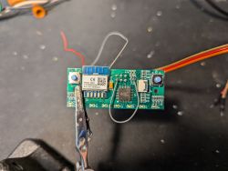
    Instead of cutting traces to silence the TuyaMCU, I went with a more delicate approach. I forced RST of the MCU to GND in order to keep it in RESET state. The TuyaMC has a 10K pullup to 5V on that /RST signal. So bridging it to GND is fairly easy.
    A circuit board with a CB2S communication module, visible with several connected wires.
    As it turns out, this is not needed. More on that below.

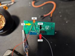
    Turns out @efirestone was right about the 2 vias being TX and RX. I took a leap of faith and soldered straight on the vias. I had to scrape the solder mask a bit to get a good connection.
    Close-up of a circuit board with labeled TX, RX, GND, and 3.3V pins.

    Then I used the BK GUI Flash tool. Everything went smoothly. No config to extract other than a baud rate value of 9600.

    As I mentioned earlier, it turns out I did not need to hold the TuyaMCU in RESET. After soldering the wires, I did a spot check and noticed the CB2S wasn't connected to the 5V rail. Double-checked its datasheet and yep, it's a 3.3V part.
    Then I noticed the 3.3V test point right beside the header.
    It turns out the TuyaMCU is powered via 5V and the CB2S through a dedicated 3.3V supply coming from the base PCB. So effectively, you can keep the TuyaMCU at bay by simply not powering the board through the 5V pin.

    I tried first with /RST tied to ground as I had already soldered it but I later retried without it, just to be sure.
    In both cases, I was able to access the flash of the CB2S without issue.

    So now my DPR30 is back in one piece, connected to my home WIFI and ready to be configured properly.

    Added this autoexec.bat onto the filesystem

    
    startDriver TuyaMCU
    setChannelType 1 toggle
    setChannelType 2 dimmer
    tuyaMcu_setBaudRate 9600
    tuyaMcu_setDimmerRange 1 1000
    linkTuyaMCUOutputToChannel 1 bool 1
    linkTuyaMCUOutputToChannel 2 val 2


    The dimmer works fine except the status LED at the bottom of the touch bar is constantly blinking like crazy.

    Where can I upload the backup bin of the original firmware?


    EDIT
    I managed to read a bit on how to interface TuyaMCU and I figured how to stop that Status LED from blinking.
    Here's my final script

    
    startDriver TuyaMCU
    setChannelType 1 toggle
    setChannelType 2 dimmer
    tuyaMcu_setBaudRate 9600
    tuyaMcu_setDimmerRange 1 1000
    linkTuyaMCUOutputToChannel 1 bool 1
    linkTuyaMCUOutputToChannel 2 val 2
    tuyaMcu_defWiFiState 4
    PowerSave 1


    I also enabled "Flag 43 - [TuyaMCU] Use queue" whatever that does. The device seems more responsive with it but I have no definitive clue on what it's for. I just saw a lot of recommendations to enable in other threads.
  • #5 21221979
    psyko_chewbacca
    Level 6  
    Ok so I managed to find how to extract dpIDs supported on a TuyaMCU.

    Here's the log output

    
    Info:TuyaMCU:ParseState: byte 1
    Debug:TuyaMCU:ApplyMapping: id 104 (val 1) not mapped
    Info:TuyaMCU:ParseState: id 108 type 2-val len 4
    Info:TuyaMCU:ParseState: int32 1000
    Debug:TuyaMCU:ApplyMapping: id 108 (val 1000) not mapped
    Info:TuyaMCU:ParseState: id 109 type 3-str len 5
    Info:TuyaMCU:ParseState: id 113 type 3-str len 5
    Info:TuyaMCU:ParseState: id 110 type 1-bool len 1
    Info:TuyaMCU:ParseState: byte 0
    Debug:TuyaMCU:ApplyMapping: id 110 (val 0) not mapped
    Info:TuyaMCU:ParseState: id 111 type 2-val len 4
    Info:TuyaMCU:ParseState: int32 0
    Debug:TuyaMCU:ApplyMapping: id 111 (val 0) not mapped
    Info:TuyaMCU:ParseState: id 114 type 1-bool len 1
    Info:TuyaMCU:ParseState: byte 0
    Debug:TuyaMCU:ApplyMapping: id 114 (val 0) not mapped
    Info:TuyaMCU:Received: 55 AA 03 03 00 00 05 
    Info:TuyaMCU:ProcessIncoming[v=3]: cmd 3 (WiFiState) len 7
    Info:TuyaMCU:Received: 55 AA 03 07 00 20 02 02 00 04 00 00 01 5C 03 02 00 04 00 00 00 C8 05 02 00 04 00 00 03 E8 65 02 00 04 00 00 00 32 F2 
    Info:TuyaMCU:ProcessIncoming[v=3]: cmd 7 (State) len 39
    Info:TuyaMCU:ParseState: id 2 type 2-val len 4
    Info:TuyaMCU:ParseState: int32 348
    Debug:TuyaMCU:ApplyMapping: mapped dp 2 value 348 to 34
    Info:TuyaMCU:ParseState: id 3 type 2-val len 4
    Info:TuyaMCU:ParseState: int32 200
    Debug:TuyaMCU:ApplyMapping: id 3 (val 200) not mapped
    Info:TuyaMCU:ParseState: id 5 type 2-val len 4
    Info:TuyaMCU:ParseState: int32 1000
    Debug:TuyaMCU:ApplyMapping: id 5 (val 1000) not mapped
    Info:TuyaMCU:ParseState: id 101 type 2-val len 4
    Info:TuyaMCU:ParseState: int32 50
    Debug:TuyaMCU:ApplyMapping: id 101 (val 50) not mapped


    Here's what I could extract and my suppositions on what unmapped dpIDs could be

    
    id1   bool  len1   toggle     (already mapped)
    id2   int32 len4   dimmer     (already mapped)
    id3   int32 len4   value:200  (ramp on delay in ms?)
    id4   enum  len1   value:3    (power on state? like ON, OFF or 'last state')
    id5   int32 len4   value:1000 (ramp off delay in ms?)
    id6   int32 len4   value:0
    id101 int32 len4   value:50   (configurable min brightness?)
    id103 enum  len1   value:1
    id104 enum  len1   value:1
    id108 int32 len4   value:1000 (configurable max brightness?)
    id109 str   len5
    id110 bool  len1   value: 0
    id111 int32 len4   value:0
    id113 str   len5
    id114 bool  len1   value: 0


    I couldn't find a lot of information on how to configure channels and what types of channels are available.
    For example, for a slider controlling (what could be) ramp off delay, should I set the channel type as "dimmer" or is there a more appropriate type?
    What a dpID of str type could be used for? Especially with a length of 5.

    I want to tinker with it to find out what all these dpIDs do but I just can't go in blind without knowing all the possible parameters of `setChannelType` command.

    Added after 8 [hours] 35 [minutes]:

    I found this thread with info on the DTR30 which is a very similar model to the DPR30. Probably only a faceplate swap.

    https://community.home-assistant.io/t/elegrp-dimmer-switch-is-it-ha-compatible/641951/7

    It has a ESPHome configuration with dpIDs listed. I will try to set OBK with this info.

    I would still like some info on how to properly configure channel types if anyone is reading!
  • ADVERTISEMENT
  • #6 21399706
    xapienz
    Level 1  
    Hello!
    Thank you for the detailed teardown of this dimmer.

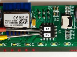
    I found that if you are not comfortable soldering or messing with the board, you can use tiny IC chip clamps and connect directly to the legs of TuyaMCU, where RX and TX of CB2S are going to. You can see the trace between the chips on the back side of the board, and it will make it easier to do less damage.
    Then I could flash CB2S using `ltchiptool` and ESPHome firmware.

    PCB with TX and RX labels on a chip and CB2S module.
  • #8 21635347
    razzamatazm
    Level 1  
    @psyko_chewbacca - did you ever get this running on OpenBeken? I've used your ESPHome config, and while it works, I feel like ESPHome has gotten less reliable lately...
  • ADVERTISEMENT
  • #9 21635694
    psyko_chewbacca
    Level 6  
    >>21635347

    Hi,

    No, I did not try OpenBeken. It's not my cup of tea.
    I too found ESPHome to be a bit less reliable the past few months but it seems to be doing fine lately. I did move from using the API to MQTT though (in the mqtt branch from my repo). It might not be entirely suited to be readily usable as it's more or less tailored to my needs. But with minimal efforts, you could make it work.
    I think the ESPHome API implementation isn't all that stable on LibreTiny platform at the moment. But I still want to stay on ESPHome framework as I do have specific features coded in that would probably be impossible to implement with OpenBeken's scripting capabilities. Hence why the move to MQTT.

    There is a https://github.com/libretiny-eu/libretiny/issues/316 on LibreTiny that awaits a fix. There is a workaround for it in "mqtt" branch.
    ESPHome did a refactor on a number of components that could have introduced memory leaks the past few releases.

    At this moment, all my devices are working reliably (fingers crossed).

Topic summary

The discussion centers on the teardown and firmware flashing of the ELEGRP Smart Dimmer DPR10, a touch-sensitive dimmer switch compatible with the ELEGRP and Tuya Smart Life apps. The device uses a CB2S (Beken BK7231N) WiFi module and integrates a TuyaMCU for dimmer control. The hardware is secured with T7 screws and includes a relay board covered by a metal shield. Flashing custom firmware such as OpenBeken or ESPHome requires accessing UART lines (RX/TX) between the WiFi module and TuyaMCU. Several methods to enable flashing are discussed: cutting or desoldering traces, forcing the MCU reset line low to hold TuyaMCU in reset, or using IC chip clamps to connect directly to the RX/TX pins. Flashing tools like BK7231GUI and ltchiptool are recommended. A firmware backup of 2MB is advised before flashing. The DPR30 model shares similar hardware with additional traveler wire circuitry. A ready-to-use ESPHome device package is available for these dimmers. Extraction of TuyaMCU dpIDs and debugging logs are also mentioned for advanced integration.
Summary generated by the language model.
ADVERTISEMENT