logo elektroda
logo elektroda
X
logo elektroda

Gosund/Ghome SW2 [BK7231T] wifi dimmer switch - subsystem identification

bkespoke 2211 26
ADVERTISEMENT
  • #1 20815331
    bkespoke
    Level 4  

    Following from the excellent SW5 teardown and template which works well for me, I am now struggling with the Gosund / Ghome SW2.
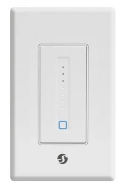
    It's a dimmer with both a traditional US Decora style press-button but also a touch front panel with a row of LEDs. Generally a high-quality product, as with all Ghome I've seen so far. Purchased from Amazon, also sold direct, $15-$20.
    FCC ID 2APUZ-SW2 UL listed ES09666 Model SW2 Date 05/2022. 120 V 4 A.
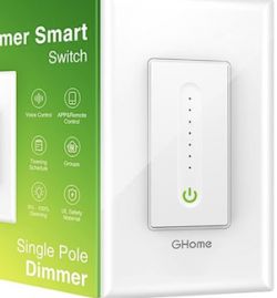
    GHome smart dimmer with voice and app control features.

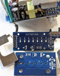
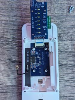
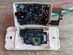
    It contains FOUR PCBs connected by thin flex cables:
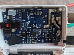
    - Main switch/relay/psu/dimmer board, including a mysterious IC "GK1DD8S003F3P6" which must do the dimming.
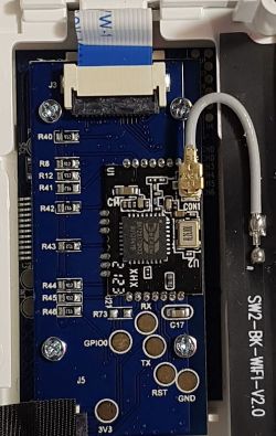
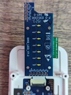
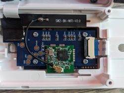
    - CPU board containing the BK7231T (module) and the seven LEDs
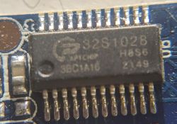
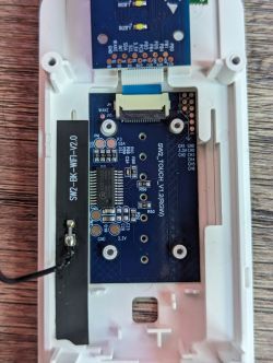
    - Touch board with an APTchip "32S1028H8S6" microcontroller.
    - 2.4 GHz antenna with coax and U.FL or IPEX

    Stock firmware offers on/off, dimming by touch / sliding finger, bar graph of LEDs, very nice.
    But it needs to run OpenBK and talk to HA.

    Questions:
    Does anyone have experience with these peripherals?
    Are there any libraries that might work?
    I can flash the BK7321 fine, but there is firmware on the other parts, which it would be best to use as-is.
    Is the next step to power it up with isolated 120 V, sniff the I2C between the boards and attempt to reverse-engineer the protocols? Urgh!
    Does the S in the APTchip indicate that it has no flash, needs to be programmed on power-up?
    I guess it would be OK to just have dimming, bar graph and wifi, ignore the touch board.

    Any other pointers or suggestions would be welcome. Am I biting off too much here?
    I'd also be happy to ship my one in pieces to a real expert...

    Thanks!


    Touch board IC:
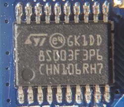
    Close-up of a microchip with visible markings and numbers.

    Dimmer board IC:
    Close-up of an integrated circuit on a printed circuit board, labeled as BL602T.

    CPU board (nice programming pads)
    Electronic circuit board with components and wiring

    General assembly:
    Teardown of Gosund SW2 LED V1.0 electronic circuit with visible components and board.
  • ADVERTISEMENT
  • Helpful post
    #2 20815398
    p.kaczmarek2
    Moderator Smart Home
    Hello, why do you think this device uses I2C?

    I'd rather think it's just yet another TuyaMCU device, which should be easily supportable by OpenBeken, altough flashing may be a bit hard due to the UART1 port being used for both programming and TuyaMCU communication. It also may be required to do the UART packets capture first, and it must be done in a safe manner. They can be later analyzed in https://github.com/openshwprojects/TuyaMCUAnalyzer

    Or maybe we could just skip the UART analysis part, just make firmware backup (just in case) and then try to flash OBK and just try to query dpIDs from device and try to guess their meaning... TuyaMCU dimmers are not usually very complicated, they are often using the same dpIDs in many different models.
    Helpful post? Buy me a coffee.
  • #3 20819144
    bkespoke
    Level 4  

    Thank you!! This pointed me in the right direction. After much investigation about TuyaMCU...

    With the stock firmware, I have found serial communications at 115200 to/from the BK7231, but not TuyaMCU packets.
    Also I2C between various things on the boards, not yet sure which parts are talking.

    A bunch of information that doesn't yet completely make sense (all values are hex)

    1) I2C seems to control the bargraph LEDs.
    Evidence: When pressing the microswitch for On, when the light was previously at full brightness, apart from the relay click, the bargraph lights run up in sequence 1 to 7. I2C packets are (writing to address A6): 00 01, then 00 03, 00 07, 00 0F, 00 1F 00 3F 00 7F.
    Turning off, they just drop instantly to a single dot, with a matching packet.

    2) Serial seems to control the dimmer.
    Evidence: When touching the dimmer touch board, with the light in the On state, apart from the LED I2C packets, now we get:
    - I2C write address A6: 01 A7
    - I2C read address A7: 00
    - BK serial RX: 24 00 01 5D 23
    -repeat- I2C write address A6: 01 A7
    -repeat- I2C read address A7: 00
    -repeat- BK serial RX: 24 00 01 5D 23
    - BK serial TX 0x41
    - BK serial TX 0x81
    - I2C write A6: 00 01 [the LED command]

    3) More serial dimming - when running a finger UP the dimmer slider:

    I2C LEDsI2C (dimmer control?)Serial RX on BK (Dimmer?)
    write:A6: 00 03read:A7: 3E 24 3E 01 5C 23
    write:A6: 00 07read:A7: 43 24 43 01 5C 23
    write:A6: 00 0Fread:A7: 4F 24 4F 01 5C 23


    3) When the relay is OFF, there are no I2C packets (because the LEDs don't change)
    But also no serial packets, so I assume whatever is Transmitting the serial dimming command is not bothering while the relay is off.

    4) The BK7231 is also sending single serial bytes at 115200, not obviously synchronised with any of the other packets, but only happening when there's some action. They're in pairs, brightness increasing:
    41 81
    41 89
    41 92
    41 98
    42 9E
    42 A3
    42 A4
    42 AA
    43 AE
    ...
    46 DA
    46 DE
    47 E4
    Maybe this could be: (0x40+number_of_LEDs_4bits 0x80+True_brightness_7bits)

    5) There's no heartbeat at all. The LED and other commands are sometimes sent a second time, 100 ms later.

    6) there's no packet on either bus associated with the relay click

    7) BUT once while flashing the BK7231 with an external serial port, forgetting the other boards connected, the relay started clicking randomly as though it was receiving a command.


    Next Steps:


    1) take one for the team and install the smart home app, send some commands that way

    2) disconnect the boards one at a time and see who is still talking to whom

    3) probe the three microcontrollers actual pins looking for these signals, to see which ones even get the various messages.


    Any other suggestions or ideas?
  • Helpful post
    #4 20825305
    bkespoke
    Level 4  
    I've finished decoding most of it now.

    tl;dr is it worth trying to get OpenBeken to speak to this dimmer?
    It's definitely not the usual TuyaMCU protocol. Is it fairly simple to write something that receives and sends these messages, updates its internal dimming state etc? The LEDs and Button are easy, but how would it parse the 5-byte serial messages to get the touch input, and send the serial dimmer and LED commands?

    Have you seen a device like this before? Shall I flash it with OBK and try sending some of these commands? Thank you!


    The gory details:

    TouchController (APTchip) - reads the touch, controls the 7 LED bargraph.

    PowerDevice controls the relay and the Triac.

    PowerDevice and TouchController speak by I2C - one message A6 00 bb is the LED mask. The other A6 01 A7 tt is the touch position.
    Also an INT line for APTchip to tell PowerDevice it's been touched
    And a WAKE line for PowerDevice to tell TouchController to listen to I2C.

    The BK7231-relevant parts are as follows:
    - Physical button connected to the BK module
    - WifiLED and PowerLED connected to BK
    - Serial TX from BK to PowerDevice is to turn relay on and off, and set dimmer (via I2C eventually).
    - Serial RX from PowerDevice is to tell BK the touch state.
    - BK not connected to I2C

    The BK sends only these bytes, 115200bps:
    OFF: 0b 0000 0aaa where aaa is 1 to 7 depending on the brightness before turning off
    ON: 0b 1ddd dddd where ddd dddd is the dimmer setting, 0-100 (percent)
    LED: 0b 0100 0ggg where ggg is the LED bargraph 1 to 7.

    It's usually sent as a two-byte message, first the LEDs then the Dimmer.
    14 ms apart. Sometimes repeated after 20-100 ms or longer, but if you're sliding the brightness on the app, it keeps sending new values, no duplicates. I don't think the timing order of the bytes is useful information, they're decoded separately.

    The reason the OFF message also contains the brightness 1-7 is so the PowerDevice can tell the TouchController to leave that single LED on, indicating how bright it will be when switched on again.

    the BK receives the touch position from PowerDevice by serial, 115200, with this 5-byte packet:
    0x24 0xTT 0x01 0x69 0x23 where TT is the touch position, approximately 0x01 to 0x96
    It then usually sends out a new dimmer setting and LED bargraph (which is then relayed by i2c...)

    At startup the PowerDevice says this 9 times on the serial port:
    Packet 1, 37 bytes: 74 6F 75 63 68 20 61 64 64 72 20 6E 6F 74 20 61 63 6B 20 77 68 65 6E 20 74 78 20 77 72 69 74 65 20 63 6D 64 21
    in english, it's saying: touch addr not ack when tx write cmd!

    Then it says
    Packet 10: 72 65 73 65 74 21 0A 6D 63 75 20 76 65 72 3A 20 76 32 2E 31 2E 32
    reset!
    mcu ver: v2.1.2


    It finally stops complaining once the TouchController ACKs the I2C

    BK says nothing on startup.

    There are no heartbeats that I've seen, complete radio silence on Serial and I2C unless there's a command on the app, button press or the touch surface is touched.
  • #5 20825371
    p.kaczmarek2
    Moderator Smart Home
    Very good job, it reminds me of WXDM2 dual dimmer, which also had a custom UART protocol. You can read about it here:
    https://www.elektroda.com/rtvforum/topic3985978.html#20631683
    Do you need help with getting that into OBK?
    Helpful post? Buy me a coffee.
  • #6 20825408
    bkespoke
    Level 4  
    Hi, I think I could get the HexSend working, and make it function as a dimmer and indicate its state on the bargraph.
    It's easy to flash, because the BK board can be isolated by disconnecting the flex cables. I'll try this tomorrow.

    Is there a way to receive the 5-byte packets, to receive the touch input?
    Or is that a major rebuild like cloning the TuyaMCU driver?

    Also - do you support dimming commands by Hue Emulation? This looks like a fairly messy process :( I don't yet have a HA server, so it would be useful to control the dimmer like this.

    Thanks!
  • #7 20825423
    p.kaczmarek2
    Moderator Smart Home
    Our Hue is not ready, but we have Wemo.

    What about creating a driver directly in C? Maybe this would be easier to support this device.

    We are usually using Tasmota apps to control OBK, like Tasmota Control, etc.
    Helpful post? Buy me a coffee.
  • ADVERTISEMENT
  • #8 20825586
    bkespoke
    Level 4  

    Sorry, I'm not up for writing a new driver in C, I'll get lost.

    Ha ha if only my internet search was as good as my logic analysis. Blakadder took the SW2 apart and decoded the protocol years ago (when it was still made with an ESP).

    Thanks for all your work on OBK, it's doing well on my other switches. I hope this post helps someone else trying to figure out the SW2.
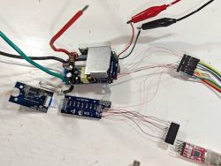
    Time to put it back together.
    Disassembled electronic circuit board with connected wires on a white background.
  • #9 20932602
    GeraldOfPataskala
    Level 1  

    Can you show how you used the Blackadder script to make it work? I assume you translated it to an autoexec.bat file?
  • #10 20932611
    p.kaczmarek2
    Moderator Smart Home
    I'm not sure if @bkespoke got it working. I could do it for you, but I don't have access to this device, I would need to get one piece for testing.
    Helpful post? Buy me a coffee.
  • #11 20932670
    bkespoke
    Level 4  
    Hi, sorry I didn't get it working at all.
    Blakadder had decoded the serial protocol from the ESP8266 to the other micro(s) in the switch, and written a script for Tasmota. This was back when the SW2 used an ESP, now they're BK7231. I just didn't find it when searching, and did it all again myself.

    It might be possible to write an OBK script to send and receive commands to make a SW2 work, but it really needs a new serial port driver and that's beyond me.

    You can see all of the commands above and on Blakadder.


    I'd be happy to test your script or set up a sandbox for you to work on the SW2. I just can't help much with the code.
  • #12 21025838
    mikekornikh
    Level 2  

    Hello! I just got the Shelly Plus wall dimmers, and it uses the exact same chips except for an ESP32 instead of the Beken. I'd love to get this working in ESPhome! Shelly Plus circuit board with mounted LEDs. Close-up of the internal electronic circuitry of a Shelly Plus wall dimmer. Internal view of a Shelly Plus wall dimmer showing circuit boards with an ESP32 chip. Interior of a Shelly Plus wall dimmer showing the electronics. View of the interior of a wall dimmer with an ESP32 chip. Interior of a Shelly Plus wall dimmer showing integrated circuits and circuitry. Shelly Plus wall dimmer with touch button and LED indicators.
  • ADVERTISEMENT
  • #13 21025865
    p.kaczmarek2
    Moderator Smart Home
    Whoa, you are lucky, how did you get one with ESP32? Which mobile app was it dedicated for, is it for Tuya or something else?
    Helpful post? Buy me a coffee.
  • #14 21025892
    bkespoke
    Level 4  

    Interesting! Perhaps I'll order one more to see if it's changed back to ESP.


    If the internal serial protocol is unchanged, there's a fairly straightforward recipe and script at Blakadder. As the boards are connected with flex PCBs it's easy to separate them so you can flash the ESP by its serial port without interference.

    Things to watch out for:

    1. Is the protocol the same? Check with a scope or logic analyzer, or even just your FTDI cable before you flash, that it's sending the same messages as I found. Likely to be ok because it was stable between 2021 and 2023. Back up the ESP firmware?

    2. The ESP will probably talk to the other micro with some non-standard serial port pins, not its usual Tx and Rx. You'll need to find them by staring at the board. See the blakadder page for the esp8266 version of this.


    Don't connect it to mains power and your computer at the same time! It's fairly easy to power the whole switch from 5 V on the relay/PSU board.
  • #16 21591363
    hardware4200
    Level 7  
    Very interesting discussion:

    I have a GHOME device SW17 having a LN882HK1 on it. I was able to successfully flash it using openbelken. However I discovered the same issue with the dimming, seems there is I2C, I am wondering if the capability to control the dimmer was added to the library. I am pretty new to all of this but I have some C chops and would be willing to take this on and figure it out.
  • #17 21593208
    divadiow
    Level 35  
    I don't believe anything has been written for the dimmer chip. Does your device have the same chips as seen in the first post in the SW2?

    Did you capture boot log for factory firmware? Maybe it has clues about driver loaded...
  • #18 21593400
    hardware4200
    Level 7  
    >>21593208 re: Boot.log. I am not sure how to capture this other than watching the UART. I have a connection to the device when it boots and I see nothing on the serial console.

    re: Chips. SW17 has a LN882HK1 (which I've successfully flashed with OB) and a 32S1028H8S6 which is the capacitive touch MCU.

    I think this could be a significant game changer if this device were adopted, as it costs roughly $7-9ea in quantities of 4.

    I am happy to do the work if there isn't anything existing, ideally someone who knows the firmware (that might be you) could give me some guidance of how I would actually implement this. I know it will require an I2C interface, but I am wondering more about how should surface this to the UI. How to select SCL/SCA, addresses.

    I am getting my environment setup to put the device on a logic probe, etc.
  • #19 21593412
    p.kaczmarek2
    Moderator Smart Home
    Helpful post? Buy me a coffee.
  • #20 21593497
    divadiow
    Level 35  
    does this help?

    https://templates.blakadder.com/gosund_SW2.html

    Code: Text
    Log in, to see the code


    https://github.com/ab0tj/esphome-devices/blob/master/gosund_sw2_output.h
    https://github.com/ab0tj/esphome-devices/blob/master/gosund_sw2_uart.h

    https://cocoontech.com/threads/gosund-wifi-dimmer-replacing-firmware.32175/

    Added after 1 [hours] 1 [minutes]:

    hardware4200 wrote:
    re: Boot.log. I am not sure how to capture this other than watching the UART. I have a connection to the device when it boots and I see nothing on the serial console.

    hmm OK. it'd be a case of flashing back factory and listening on B9. or send me dump and I'll flash and capture.

    Added after 1 [hours] 2 [minutes]:

    http://en.aptchip.com/list_112/655.html#gongju

    Part NO.Op.VoltTempFreqPinGPIOHSIOFlashRAMDflashHWDIWDTWWDTBTCNTARTCLPTEPTGPTUARTIICSPINOTTTLPWMADCTouchDeep SleepPACKAGE
    APT32S1028H8S61.8v~5.5v-40~8548MHz2422464k4k2k11211111311116bit,12ch12bitx16ch17ch5uASSOP24


    looks like a CK-Link type chip http://en.aptchip.com/tiaoshi
  • #21 21593661
    p.kaczmarek2
    Moderator Smart Home
    There seem to be some confusion, the linked driver is a simple UART byte send, I can port it easily.

    I've started porting it, but it's not I2C so it may not fit your device, but anyway...
    Gosund/Ghome SW2 [BK7231T] wifi dimmer switch - subsystem identification
    https://github.com/openshwprojects/OpenBK7231T_App/pull/1702
    Futhermore, on which platform should I enable it? LN882H?

    I am also missing one more thing - what is the baud rate there?
    Helpful post? Buy me a coffee.
  • #22 21594088
    bkespoke
    Level 4  
    Re >>21593661
    The baud rate on the serial port was 115200 - for the dimming control messages, and the startup message.

    I still have the .logic captures for various operations of the dimmer, but my summary in >>20825305 contains everything I could figure out. I never tried sending the various codes from openbk to the dimmer controller.

    If you have firmware for it, and I'm the only one with hardware, I could probably flash it and try it out.
  • #23 21594301
    p.kaczmarek2
    Moderator Smart Home
    Well, that does not match the SW2 driver I ported... maybe we could do driver according to your specs, but I am not sure if info is complete. Do you know C basics?
    Helpful post? Buy me a coffee.
  • #24 21594323
    bkespoke
    Level 4  
    Me? I can read C and hack it but not construct a whole interconnected application.

    Quote:
    that does not match the SW2 driver I ported

    From where? Perhaps the power driver microcontroller and hence its interface has been changed. My dimmer is almost 2 years old now.

    What I said about my 2023 device and investigations:
    Quote:
    The BK sends only these bytes, 115200bps:
    OFF: 0b 0000 0aaa where aaa is 1 to 7 depending on the brightness before turning off
    ON: 0b 1ddd dddd where ddd dddd is the dimmer setting, 0-100 (percent)
    LED: 0b 0100 0ggg where ggg is the LED bargraph 1 to 7.


    To explain my earlier writing a bit more carefully:
    On every power state change the BK should send something like this at 115200 bps
    1. the LED byte which is 0x40 | (state*7)
    2. pause 14 ms (this is 200 characters, a non-trivial delay (could experiment to see if it needs to be so long. Perhaps the dimmer micro can't receive serial while talking to the display on I2C?)
    3. the dimmer setting which if the power is on, should be 0x80 | (state*127).
    If the power is off, send 0x00 | (state*7) (I can't remember why the state is required. Perhaps this takes precedence over the LED byte if power is off. Dimmer LEDs??)
    4. Repeat the above a second time after 100 ms of idle time (guarding against corruption?)
    5. Max rate of about 100 ms, even if the touch input is coming in every 40 ms.

    This isn't quite what's in DRV_GosundSW2_Write() in your new code. - you're only controlling the dimmer, not the bargraph LEDs.

    DRV_GosundSW2_RunFrame() looks OK. No idea if it will stay synchronised, maybe that's taken care of by a short timeout. From my logic analyser captures, the 5-byte frames arrive about every 39 - 50 ms when sliding your finger on the touch strip.
    You'll need to adjust the touch strip limits to ensure you can get 100% and 0%. I got values up to 0x96 which is 150, so maybe use float dimmerVal = constrain(buff[1] / 145.0, 0.0, 1.0) or something.


    The original Ghome firmware has some further neat functionality for the bargraph:
    - at least one dot always showing
    - remembers the brightness when you switched off by pressing the button
    - displays this last brightness so you know what you'll get when pressing
    - possibly accepts touch inputs to change brightness while the light is off, so you can pre-dim it before turning on with the physical switch
    These could be emulated in various ways.
  • #25 21594484
    divadiow
    Level 35  
    bkespoke wrote:
    and the startup message.


    thanks for the dump of your BK7231T SW2 factory firmware. Here is boot log (on dev board so missing the other components in dimmer of course)

    Code: Text
    Log in, to see the code


    Code: Text
    Log in, to see the code
  • ADVERTISEMENT
  • #26 21600913
    hardware4200
    Level 7  
    >>21593412
    p.kaczmarek2 wrote:
    But do we know the protocol?

    Regarding code - copy sample driver, or some driver using I2C, and build from there:
    https://github.com/openshwprojects/OpenBK7231T_App/blob/main/src/driver/drv_sht3x.c
    How to create a custom driver for OpenBeken with online builds (no toolchain required)


    Thanks for the above. Apologies for the delayed response, been real busy here. I am going to take this on and try to figure it out. Appreciate the pointers.

    Added after 10 [minutes]:

    >>21594301 If you are asking me. Yeah, I have some decent C chops. I need to go through the links that have already been provided and figure out how I would implement/catch the I2C communication and pass that to TRIAC that controls the dimming.
  • #27 21601119
    bkespoke
    Level 4  
    @hardware4200 The BK7231 doesn't use I2C - it only speaks on the serial port, to the dimmer controller ST Micro.

    Here's a sketch of the whole unit.
    Gosund/Ghome SW2 [BK7231T] wifi dimmer switch - subsystem identification
    It looks like it was cobbled together from existing / working parts, not designed from the ground up (some risk of it being redesigned...)

    Edit: We may be talking about different units - there's also a "shelly" ESP32 version. Though from the photos it is likely the same control arrangement. Maybe Mike can confirm this. It took me a while to figure out that the I2C passes through the main board, even has test pads there, but it's not a common bus, not even connected to the BK7231.

Topic summary

The discussion focuses on the Gosund/Ghome SW2 WiFi dimmer switch featuring a BK7231T CPU module, a dimmer MCU labeled "GK1DD8S003F3P6," an APTchip 32S1028H8S6 touch controller, and a 2.4 GHz antenna. The device uses a complex subsystem with four interconnected PCBs communicating via I2C and serial interfaces. The bargraph LEDs are controlled over I2C, while dimming commands and touch inputs are exchanged through a custom 5-byte serial protocol at 115200 baud, distinct from the common TuyaMCU protocol. Efforts to integrate the device with OpenBeken (OBK) firmware highlight challenges due to the proprietary serial protocol and the need for a new serial driver. Flashing the BK7231T is feasible by isolating the CPU board, but decoding and implementing the dimmer control requires detailed protocol analysis and custom scripting. Related devices like the Shelly Plus wall dimmer use similar chips but with ESP32 instead of BK7231. Community members reference Blakadder’s prior ESP8266-based protocol reverse engineering and Tasmota scripts as starting points. The discussion also touches on potential development of custom drivers in C, I2C protocol reverse engineering, and integration with home automation platforms such as Home Assistant and Wemo. The conversation includes boot log analysis, logic captures, and firmware dumps to aid in understanding the device’s communication and control mechanisms.
Summary generated by the language model.
ADVERTISEMENT