logo elektroda
logo elektroda
X
logo elektroda
Dostępna jest polska wersja

Czy wolisz polską wersję strony elektroda?

Nie, dziękuję Przekieruj mnie tam

[BK7231] Martin Jerry Single Pole Smart Switch US-SS01 Flashing Guide & Template GPIO

xSPARExSTEWx  1 2745 Cool? (+2)
📢 Listen (AI):

TL;DR

  • A Martin Jerry US-SS01 single-pole smart switch with a WB2S/BK7231T board was opened, flashed with OpenBK7231, and configured with a manual GPIO template.
  • The key trick was soldering 3.3V, GND, RX, TX, and momentarily grounding CEN, while disconnecting RX from the main board to enter flashing mode.
  • The switches came in a 4-pack for $52, and the pin map used P8 "Rel", P10 "Btn", P24 "WiFiLED", and P26 "LED_n".
  • After flashing, the device broadcasted an OpenBK7312T_XXXXX access point, connected to 2.4GHz Wi‑Fi, and was discoverable in Home Assistant via MQTT.
  • The setup requires manual module configuration, and the author notes the CEN timing is the hardest part of flashing.
Summary generated by AI based on the discussion content.

This switch was actually pretty easy to figure out and flash/configure thanks to the OpenBK team. I am mainly using the Feit Smart Dimmer switches as my local Costco had the $.00 manager clearance sale on them for $7 for a 2 pack a few months ago. So I bought all 13 2 packs they had left. Now nearly every light switch is smart and dimmable in my house. Thanks bleeblak8 for figuring out that one to get me started and have some foundation to figure out this one.

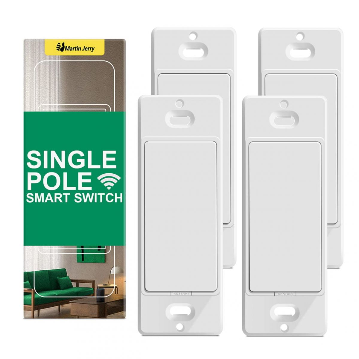
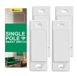
I wanted to control a few fans and could not easily figure out how to disable the dimmer safely, so I bought a 4 pack of Martin Jerry switches for $52 (almost 4x what I paid for the Feit ones lol) as it seemed like they were all cheap ESP devices that I could easily flash tasmota on, but the US-SS01 has the WB2S WiFi board instead. This is the same BK7231 in the Feit so I poked around to see if I could easily flash it. Turns out it was very easy to open and flash. Took me about 3 hours to figure this all out.
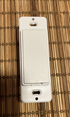


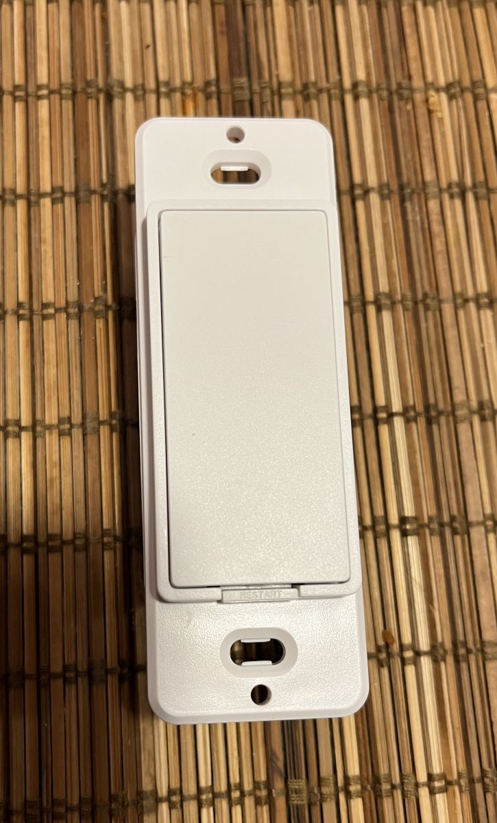
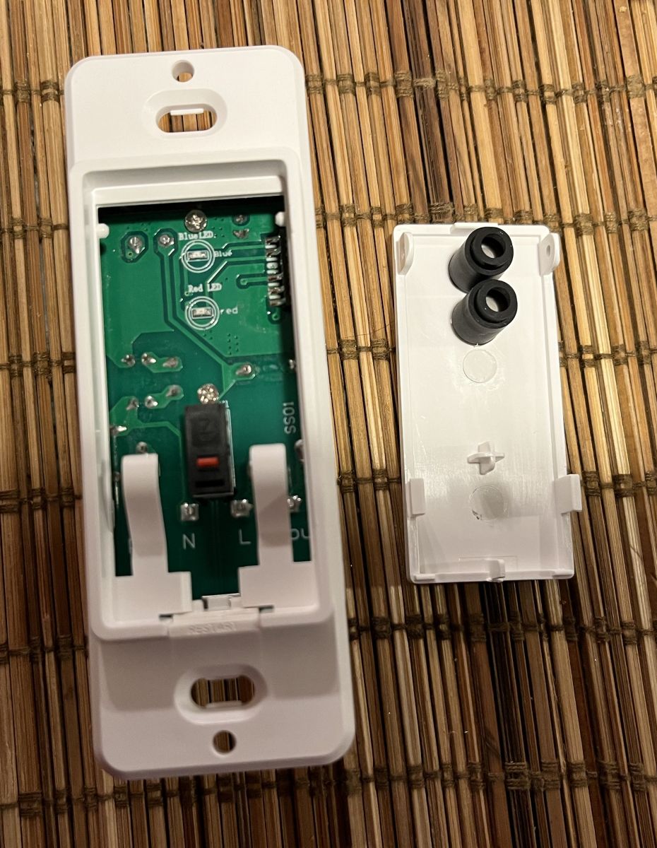
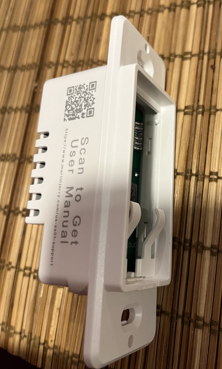
All the plastic is held together by tabs so it is easily removed. All we need to do is pop off the button.
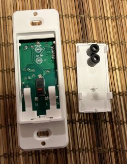


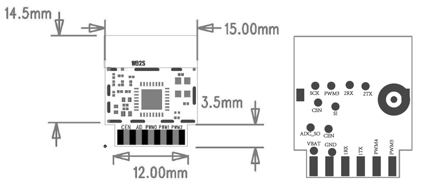
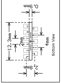
Now the little board that is sticking out on the top right is the WB2S, luckily everything we need is accessible from this side of the board. Here is the pin out if you want to get a better feel of what we are doing.
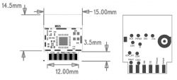
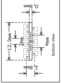


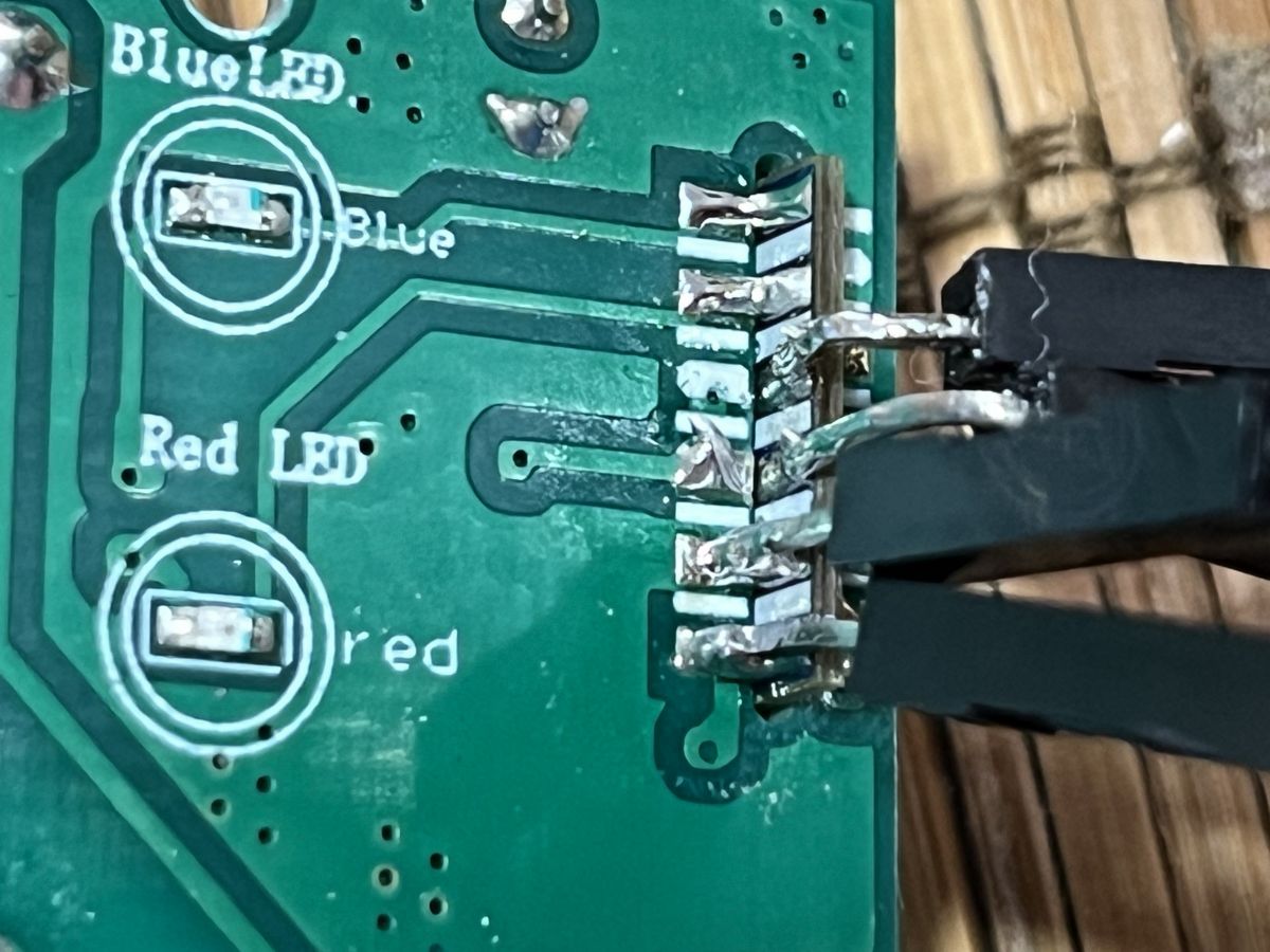
3.3v (VBAT), GND, RX, TX are all facing the LEDs, from the bottom up. We will need to solder leads to each of them or you might even be able to use thin alligator clips as the pins are zig-zagged with gaps or just insulate the other side from making contact. If you are worried about melting the plastic or want more room to work you can completely take the board out. All you have to do is undo 4 tabs between the plate that goes on the wall and the back part of the unit. I did this for my first one as I was figuring it out, but the other 3 I did not.
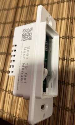


Now RX is connected to the main board and it will not flash if it is. I used a solder sucker and my iron to remove the connection and add a little back to the WiFi board so I can connect my lead. Other solder removal tricks like a wick should work here too. Hopefully you can see this in my photo below. I would do this connection first.
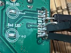


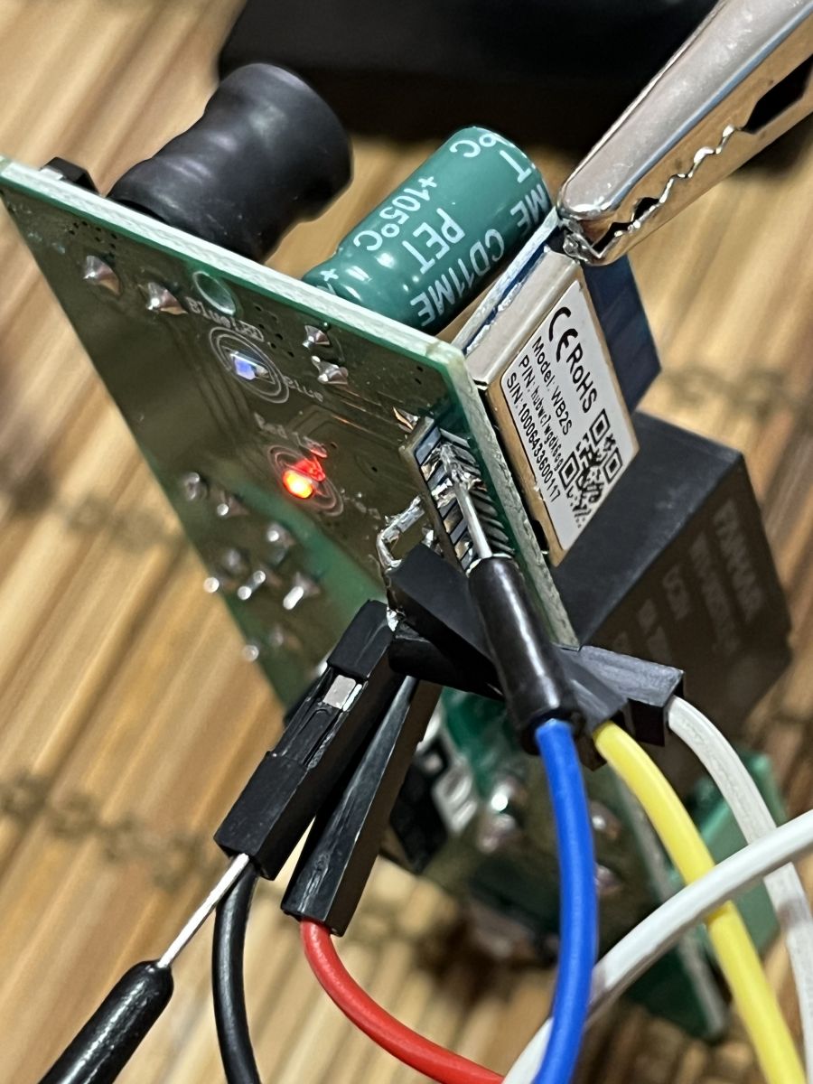
You will need 2 leads for ground as you will have to momentary ground CEN on the other side to get into flashing mode. In the photo below the blue lead is actually touching the very top pad, but only looks like it is on the 2nd from the top. The other side is stabbed in the back of the ground lead. You could use a button to make this very easy to get timing correct during flashing.
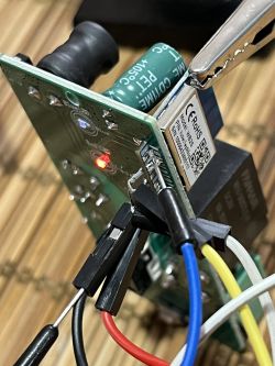


Once you are all soldered we are ready to flash.

Download the latest OpenBK7231 flasher https://github.com/openshwprojects/BK7231GUIFlashTool/releases
Select BK7231T under chip type
Click download latest from web
Plug in your USB to UART. Connect the 3.3v, ground, RX and TX (remember RX from the board goes to TX on the USB UART and TX to RX) Do not have anything else connected while flashing or working on the board!
Click either "Do backup and flash new" or "Do firmware write (no backup!)". I do the 2nd as I will not need the old firmware again.
Now it is going to have some yellow text asking you to restart the device. This is when you connect CEN to ground for about a second. Getting the timing is the hardest part. It took me a few times and I accidentally did it again while it was erasing. If it has already erased part of it you should no longer need to do this as it will just connect and flash automatically.

Once it is done flashing remove power from the device and re-power it. You can put it back together now, but I like to make sure it flashed correctly first. Once you power it back up you should see a new open WiFi network like OpenBK7312T_XXXXX with the Xs being something else. Once connected go to 192.168.4.1 in your browser.

I configure WiFi first so I can get internet back on my laptop again right away. So go to "Config" -> "Configure WiFi" and then type in your WiFi SSID and Password. This device is 2.4ghz only so make sure the network your connecting to is 2.4ghz. Now it will try to connect to your network. Login to you router and find the switches IP address. It will be named the same thing as it's network was. Type in the new IP and it should take you back to the same main screen again.

In the Web App of OpenBK there is a way to select a device to auto populate the pin config, but I am not sure how to add this switch to that right now so you will have to manually do it. The switch will not function at all if you don't do this. Click "Config" -> "Configure Module" and enter the following:

P8 "Rel" 1
P10 "Btn" 1
P24 "WiFiLED"
P26 "LED_n" 1
Click save at the bottom and it is all ready to go now! When you are ready to put it back together just unsolder all the leads and reconnect RX to the main board again.

This config is set up so that when it is trying to connect to WiFi a red LED will flash, but be off once it does. If you want it to be on while connected to WiFi select "WiFiLED_n" instead. It is also set up so that while the switch is off the blue LED will be off, and while it is on the blue LED will be on. You can invert this by selecting "LED" instead. You can switch the colors by flipping the setting between 24 and 26 too or completely disable them by selecting nothing on either or both. Also, you can keep either LED on 24/7 while the switch has power by selecting "LED" and entering a different number than 1, but this will add a 2nd "switch" on the home page and in Home Assistant which will control the LED.

All that is left to set up is the name of the switch, and MQTT on the device and Home Assistant.

On the switches home page click "Config" -> "Configure MQTT". You will need to fill out the host which is your MQTT server, Client Topic which can be anything (I just do what I named the switch), and the MQTT servers username and password. Then in the config at the bottom click on "Home Assistant Configuration" and then "Start Home Assistant Discovery". Home Assistant should find the switch if MQTT is setup correctly.


Code: JSON
Log in, to see the code

About Author
xSPARExSTEWx wrote 4 posts with rating 5 . Been with us since 2023 year.

Comments

N0ctrnl 24 Jan 2026 21:36

I bought a 4-pack of these quite a while back. Flashed them and just put them on the shelf for when needed. They worked when I put them away but after pulling one out, hooking it up, upgrading it, the... [Read more]

FAQ

TL;DR: In about 3 hours, one user found the Martin Jerry US-SS01 “very easy to open and flash” with OpenBK7231 on its WB2S/BK7231T module. This FAQ helps OpenBK users wire, flash, map GPIOs, and fix the known button issue seen after newer firmware upgrades on this switch. [#20670667]

Why it matters: This thread gives a complete, device-specific flashing path for a BK7231T wall switch, plus a real firmware regression note that can save hours of troubleshooting.

Device Wireless module Chip Purchase detail Best use from thread
Martin Jerry US-SS01 WB2S BK7231T 4-pack for $52 Non-dimming on/off loads such as fans
Feit Smart Dimmer Not stated in template block Same BK7231 family $7 for a 2-pack on manager clearance Cheap dimmable lighting control

Key insight: The critical hardware step is isolating the WB2S RX pad from the main board before flashing. The critical software caveat is that firmware 1.18.248 was reported to break the physical button, while 1.17.797 still worked.

Quick Facts

  • The switch uses a WB2S Wi-Fi board with a BK7231T chip, and the working OpenBK module map is P8=Rel 1, P10=Btn 1, P24=WiFiLED, P26=LED_n 1. [#20670667]
  • Flashing uses 3.3V, GND, RX, and TX on the WB2S side facing the LEDs, ordered from the bottom up. [#20670667]
  • The author bought Martin Jerry switches as a 4-pack for $52, compared with Feit dimmers bought earlier for $7 per 2-pack on clearance. [#20670667]
  • To enter flash mode, the thread says to momentarily ground CEN for about 1 second when the flasher asks for a device restart. [#20670667]
  • A later report says the button worked on OpenBK 1.17.797 but stopped working after upgrading to 1.18.248. [#21818741]

How do I flash a Martin Jerry US-SS01 single pole smart switch with OpenBK7231 on the WB2S/BK7231T module?

Flash it by exposing the WB2S board, wiring a 3.3V USB-to-UART adapter, and using the OpenBK7231 GUI Flash Tool with chip type BK7231T. 1. Pop off the button and access the WB2S pads. 2. Disconnect the RX pad from the main board, then wire 3.3V, GND, RX, and TX. 3. In the flasher, choose BK7231T, start flashing, and briefly ground CEN for about 1 second when prompted to restart. [#20670667]

What GPIO template should I use for the Martin Jerry US-SS01 in OpenBK7231 so the relay, button, and LEDs work correctly?

Use P8 as Rel 1, P10 as Btn 1, P24 as WiFiLED, and P26 as LED_n 1. That mapping enables the relay, the physical button, and both status LEDs on the Martin Jerry US-SS01. The thread also includes the same values in JSON for the WB2S/BK7231T board: pins 8, 10, 24, and 26 are the only configured GPIOs. [#20670667]

Why do I need to disconnect the RX pad from the main board before flashing the Martin Jerry US-SS01?

You need to disconnect RX because the thread states the switch will not flash while RX remains tied to the main board. The author removed that connection with a solder sucker and then added solder back on the Wi-Fi board side for the UART lead. Do that hardware isolation first, because it is the main flashing blocker on this model. [#20670667]

What is the WB2S module, and how does it relate to the BK7231T chip in smart switches like the Martin Jerry US-SS01?

"WB2S" is a Wi-Fi module that carries the BK7231T system chip, provides the switch’s wireless control, and exposes pads used for serial flashing. In this thread, the Martin Jerry US-SS01 uses a WB2S board, and the author notes it is the same BK7231 family used in the Feit device they had already flashed. [#20670667]

What is the CEN pin on a BK7231T board, and how is it used to enter flashing mode?

"CEN" is a control pin that lets the BK7231T enter the boot state needed for firmware flashing, using a brief ground pulse at the right moment. Here, the author used a second ground lead and momentarily connected CEN to ground for about 1 second after the flasher displayed the restart prompt. [#20670667]

Which pins on the WB2S board are 3.3V, GND, RX, and TX when flashing the Martin Jerry US-SS01?

On this switch, 3.3V, GND, RX, and TX are the four pads facing the LEDs, ordered from the bottom up. The thread explicitly identifies them as VBAT for 3.3V, then GND, RX, and TX. You must also cross the serial lines correctly: board RX goes to USB-UART TX, and board TX goes to USB-UART RX. [#20670667]

Why does the Martin Jerry US-SS01 button stop working on OpenBK firmware 1.18.248 while it still works on 1.17.797?

The thread reports a firmware regression, not a proven hardware fault. A later user said the switches worked when first flashed, but after upgrading, the physical button stopped responding on 1.18.248 and worked again after downgrading to 1.17.797. That points to a codebase change between those two versions rather than a wiring change on the switch itself. [#21818741]

What troubleshooting steps should I try if the physical button on a flashed Martin Jerry US-SS01 no longer responds after a firmware upgrade?

First, verify the firmware version and the button pin mapping. 1. Check that P10 is still set to Btn 1. 2. Compare behavior on 1.18.248 versus 1.17.797. 3. Downgrade to 1.17.797 if the button failed only after the upgrade. The thread’s failure case is specific: one user restored button operation by rolling back from 1.18.248 to 1.17.797. [#21818741]

How do I configure Wi-Fi, MQTT, and Home Assistant discovery after flashing a Martin Jerry US-SS01 with OpenBK7231?

After flashing, connect to the device’s temporary OpenBK Wi-Fi network, then configure Wi-Fi, MQTT, and Home Assistant discovery from the web interface. The thread says to browse to 192.168.4.1, set your 2.4GHz SSID and password under Configure WiFi, then enter the MQTT host, client topic, username, and password under Configure MQTT. After that, click Home Assistant Configuration and Start Home Assistant Discovery. [#20670667]

How can I change the red and blue LED behavior on the Martin Jerry US-SS01 in OpenBK7231?

Change LED behavior by reassigning P24 and P26 or by swapping normal and inverted LED roles. In the posted setup, the red LED flashes during Wi-Fi connection attempts and turns off after connection, while the blue LED follows relay state. You can invert behavior with LED instead of LED_n, swap colors by flipping pins 24 and 26, or disable either LED by leaving its function unassigned. [#20670667]

What’s the difference between using LED, LED_n, WiFiLED, and WiFiLED_n in an OpenBK7231 pin configuration?

LED and WiFiLED are normal-output indicators, while LED_n and WiFiLED_n invert the active state. In this thread, LED_n on P26 makes the blue LED follow the switch state with inverted logic, and WiFiLED on P24 makes the red LED flash during connection attempts and turn off after Wi-Fi connects. The author also notes WiFiLED_n would keep the Wi-Fi LED on while connected. [#20670667]

How does the Martin Jerry US-SS01 compare with the Feit Smart Dimmer for OpenBK7231 flashing and smart fan control?

The Martin Jerry US-SS01 cost more, but it was chosen because it is a plain switch better suited to fans. The author says they could not easily disable dimming safely on the Feit Smart Dimmer, so they bought the Martin Jerry 4-pack for $52. They also say the US-SS01 was easy to open and flash, while the Feit devices had already provided the BK7231 foundation. [#20670667]

What should I do if the OpenBK7231 GUI Flash Tool does not detect the BK7231T switch after I ground CEN?

Retry the timing and check whether the chip has already started erasing. The author says grounding CEN at the restart prompt was the hardest part and took a few tries. They also note that once part of the flash was erased, the tool no longer needed that step and would connect and flash automatically. If detection still fails, confirm RX was disconnected from the main board. [#20670667]

Which USB-to-UART wiring mistakes most often prevent a BK7231T-based switch from flashing successfully?

The most common mistakes in this thread are wrong serial crossover, leaving extra connections attached, and keeping RX tied to the main board. Board RX must go to USB-UART TX, and board TX must go to USB-UART RX. Use only 3.3V, GND, RX, and TX during flashing, and do not have anything else connected while working on the board. [#20670667]

What safety precautions should I follow when opening, soldering, and flashing a mains-powered smart switch like the Martin Jerry US-SS01?

Work with the switch completely unpowered, use only a 3.3V USB-to-UART adapter for flashing, and avoid accidental shorts while the board is exposed. The thread recommends removing the board if you want more room or want to avoid melting plastic, and it warns not to have anything else connected during flashing. The author also used insulation and careful lead placement because the WB2S pads are close together. [#20670667]
Summary generated by AI based on the discussion content.
%}