Another Solar Tracker - controller and description of the structure
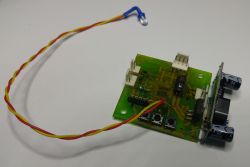
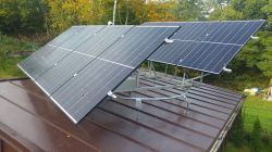
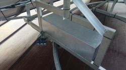
Today I am presenting another controller of my creation for the solar tracker (the first one from 2011 is described here: Photovoltaic panel turntable controller ). This time, a rudder designed for a friend who made the mechanics himself based on an old trampoline, or more precisely, its rim with a welded-in gear. Everything is placed on a relatively flat garage roof, mounted on pins with stiffening reinforcements. They are not in the attached photos yet (actually there is one, the rest are being made). The structure with panels rolls on rollers, and there are similar rollers on the bottom to prevent the wind from blowing away the "sail". The rotation could be 360 degrees, but for obvious reasons it is limited to about 260-270. If by some miracle the limit switches do not work, the rack will simply run out and the movement will stop, and the engine will turn off automatically after a short time (time protection in the program will activate). The controller is single-axis (panorama only) - these were the assumptions.
It would seem that tracking the sun could be done using one or two comparators and the matter would be solved - nothing could be further from the truth. As my experience has shown, a good algorithm means failure-free and fruitful operation of the whole. There are two schools of following the sun: 1-tracking, 2-clocking. I support option 1 and no one has yet had strong enough arguments to convince me to choose option 2.
So what does my driver have in it? It is based on Atmega168 (smd), and the program takes about 8kb written in C (predecessor in BASCOM. First of all, all movement options, buttons, etc. are protected by a time delay, e.g. there is no sudden change of direction without waiting first at least 1-2 seconds (longer in some situations).
The controller manages two 24V relays, switching on and changing the direction of a three-phase motor (a friend had one and it suited his project). If there was a sudden turnaround without time delay, it is easy to imagine that even a strong fuse would blow.
The light sensor consists of two phototransistors placed with a partition in the dome camera housing (hermetically improved). This casing worked well in the first project, so why drill down.
There is no additional photoresistor, which is sometimes found in other controllers of this type, to determine the parking level, and I am surprised by such solutions, because it is completely pointless, having two photoelements on board, which are perfectly capable of assessing the light level. The use of phototransistors instead of photoresistors as directional sensors is also important, because it is impossible to wake up the system by shining a typical, popular LED flashlight on the sensor, even if someone wanted to do it out of curiosity or malice.
At the startup and installation stage, I updated the software a few times, correcting minor errors or adding simplifications, but this is a normal process in a living organism, because the fact that everything works beautifully on the desk is only a theory, and practice usually quickly verifies it.
Currently, the positioner copes well with the sun, gets up and goes to sleep when the time comes, and the sleeping position in this (as well as in my first tracker) is the southern position. This is an almost ideal position for our region, because 90% of the wind blows from the west, sometimes slightly from the southwest, and it is also an excellent anti-wind position (the panels facing the wind offer little resistance).. Plus, it's the best place to start tracking. No, not the eastern one, I don't agree with that and no one will convince me that the eastern part is better.
Main features of the controller:
- tracking in both directions east - west,
- on-demand programming of the tracking threshold (brightness level at which work starts and ends) stored in the eeprom memory,
- tracking interval of at least 10 minutes (fixed), sometimes depending on the sunlight or lack thereof, after the countdown there is a waiting time for stronger light,
- protection against momentary flashes (the sensor must be in a clear lighting state for at least 2 seconds),
- manual positioning with tracker buttons in both directions (e.g. for maintenance purposes),
- time protection against failure to reach the target (tracking, parking) and related personalized alarms to quickly determine the cause of the fault,
- manual shortening of time delays (tracking interval, parking on demand, wake-up) for maintenance and testing purposes using a button,
- each controller state is signaled by an individual, very intuitive and clear LED blinking time combination (9 states),
- the parking position is determined by an additional switch (in this case the southern one),
- all limit switches are connected to the processor via optocouplers for safety reasons (e.g. induction of voltages in the cables).
The rudder also has an anti-wind input prepared and it is partially programmed (the executive part, i.e. parking on the southern end switch regardless of which side of the end switch it is located on), but my friend does not have any sensor at the moment and does not know the parameters to which the program should respond, so for now the input is unused and inactive.
I do not share the program. Let the above description be an inspiration for someone who would like to make such a rudder but does not know what functions to equip it with.
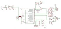
And finally, a few photos.
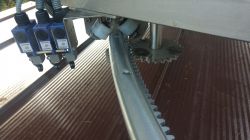
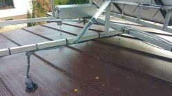
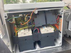
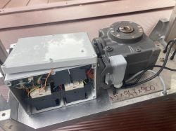
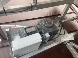
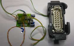
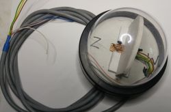
The video shows a part of the ride during calibration right after turning it on.


Comments
Cool driver. What is the total cost of RBH? Why not something industrial? Even this Logo! to be enough, you can add a preview online, etc., etc. I don't like the use of the yellow-green cable to control... [Read more]
And how does tracking perform in full cloud cover, when it is difficult to obtain a differential signal from phototransistors? [Read more]
The electronic side - costs about PLN 100, but the execution (diagram, board, soldering) requires a day's work. The program took a total of 1-2 days (including tests). The rest (mechanics, box, contactors,... [Read more]
What is the estimated energy cost of such control? How much energy does the operation of the controller and actuators consume? Did you count it? [Read more]
@Sofeicz, I didn't count. I'm taking a common sense approach here :) Taking into account the 10-minute interval with several seconds of movement and the correct setting of the tracking threshold,... [Read more]
Maybe I'll try :) In option 1, the main problem is the possibility of contamination of the optics. If a bird leaves its white substance on the western or eastern part, the system will immediately... [Read more]
Well, sorry, but the complexity of the system you describe begs for systematic failures :) Still not convinced. In fact, most opponents of tracking write about sensor contamination. Pay attention to its... [Read more]
I don't see any room for systematic failures. Reed switches are a very good solution - they are effective and practically failure-free. Basically, you can reduce their number by 2, i.e. make synchronization... [Read more]
How did you solve the problem of defining hysteresis? I once saw a similar controller that had the disadvantage that when reaching the target point, it fell into oscillations caused by too narrow hys... [Read more]
You can also do it differently - add only the limit switches (actually, you should only add one "morning"), and determine the position using the light barrier installed on the lower gear. Then we simply... [Read more]
For tooth counting, an inductive sensor reacting to metal or an encoder on the motor will be better. [Read more]
How many kilowatts does it take to turn the tracker? Does it really matter? But to the point: no one can convince you to choose 'option number 2', i.e. clock-based positioning. And for me to... [Read more]
If I were to play with these blocks on a larger scale, because I play on a micro scale, that's why I observe topics like this and I had the right conditions, I would rather choose trackers, and rather... [Read more]
There is no problem with hysteresis, because it takes a stable 2 seconds to change the sensor state, and after making a movement, the lock is immediately activated for 10 minutes. My first solution... [Read more]
Are you sure? Please correct me if I'm wrong, but aren't tracker installations most often made in such a way that the panels are placed 'lying down' during windy conditions? If so, it is... [Read more]
It depends on who writes the software :) Most of the trackers I've read about do just that, i.e. place the panels, while I position them quite sharply vertically and sideways to the wind. This solution... [Read more]
Nicely made, I've seen a similar diagram - 4 phototransistors that can be placed in two planes. [Read more]
Thanks :) Initially, I was going to make a universal version with two axles, but my friend doesn't even plan on changing the design, so I only made him a left-right one. [Read more]
It is much more difficult to follow the sun in two planes - especially mechanically. Once at school we had a purely conceptual project to think about how to do it using op. amps as follow-up regulators. ... [Read more]