How to flash LN882H with open source Tasmota/Esphome style firmware - backup procedure included
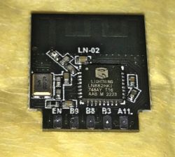
Here I will show you how you can easily flash the new LN882 modules via UART, just like you would flash ESP8266. Flashing those modules will soon allow you to free them from the cloud and connect them to Home Assistant. I've already covered some of the more technical details in the LN882H datasheet topic, so here I will only present the firmware change guide.
2025.01.04 UPDATE:
Please see this topic for latest discussion and YOUTUBE LN882H tutorial.
Update 2026
As of 2026, this platform read/write is also supported by our flash tool:
https://github.com/openshwprojects/BK7231GUIFlashTool
The connection (soldering, wires), is the same, but you can use our tool instead of the legacy one.
Please check it out and use it instead of legacy tools, let us know how it works for you!
Hardware preparation
You will need an USB to UART converter and a reliable 3.3V power supply. Powering directly from 3.3V pin on USB to UART converter may not work.
The procedure is very similiar to ESP8266 and BK7231, so watch our flashing tutorials here:
https://www.youtube.com/@elektrodacom
But basically, in case of LN882, you need to connect:
- Module TX -> UART RX
- Module RX -> UART TX
- Module GND -> UART GND
- Module 3V3 -> UART 3V3 (make sure your USB UART supports and is in 3V3 mode if it is selectable)
- Module BOOT/GPIOA9 -> GND
GPIOA9 must remain LOW during whole flashing process (do not disconnect it!.
Then, once all connections are done, connect USB to UART converter to your PC.
NOTE: if you try to flash and it fails, or you want to flash again, make sure to disconnect and reconnect USB to UART converter from your PC, while keeping BOOT signal low.
Soldering tips
If you are new to soldering, you can watch some of our BK7231 flashing guides, BK7231 is a different module but soldering method is the same. For example:
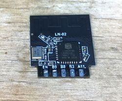
Module can be easily desoldered with some flux, some extra Pb solder, and solder wick.
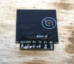
Here is desoldered module:
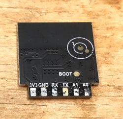
In order to solder wires easily, first add some flux:
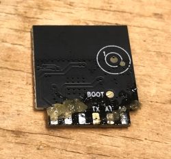
Then add some Pb solder to the pads (also tin the wires):
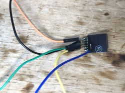
Then, solder wires:
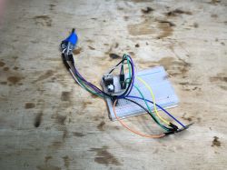
And, finally, here is my circuit - it's an USB to UART converter in 3.3V mode with an extra AMS1117-3.3V / TC1264-3.3V LDO on proto board so I can get reliable 3.3V current source:
Making original firmware backup
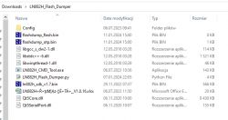
Extract both archives to single directory, like:
Navigate to it in CMD, install Python if you're missing it, change COMx to your COM port name, like COM15, run the command:
python LN882H_Flash_Dumper.py COMx flashdump
NOTE: You must have in the same directory as Python script! Otherwise, you will get this error:
If you have connected something incorrectly, or swapped RX and TX, you will get:
Otherwise, the slow and long flash dump procedure will begin:

Flash read will continue until it hits the end of the flash, it will end with following message:
This is not an error! Dump files will be created here:
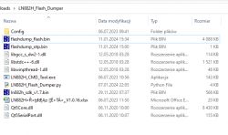
Flashing new firmware
First, get new firmware for NL882H platform, it should be available here, either check link or Releases tab:
https://github.com/openshwprojects/OpenBK7231T_App/blob/main/docs/LN882H.md
https://github.com/openshwprojects/OpenBK7231T_App
Navigate to the dir, just like when doing flash backup, then use:
LN882H_CMD_Tool.exe COMx download flash 921000 0x0 flashimage.bin
It should flash in few moments:
To run firmware, disconnect everything from power, disconnect BOOT from ground, and reconnect power:

Connect to the access point, open page at 192.168.4.1 and configure your device like you'd configure any other OpenBeken/OpenBL602/OpenW600/OpenW800/OpenXR809/Tasmota device.
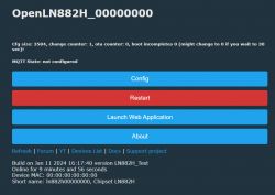
For mode OBK tips, please see our channel:
https://www.youtube.com/@elektrodacom
For a generic IoT devices teardowns list and guides list, see:
https://openbekeniot.github.io/webapp/devicesList.html
Download
Here are tools used for flashing, as described in this topic:
Summary
LN882H is very easily flashable via UART, just like ESP. You need to solder 5 wires: 3.3V, ground, RX, TX and boot signal, boot must be pulled low for bootloader to work. Remember to power off/on whole module after each flashing cycle, this is mandatory. The flashing procedure will allow you to flash our multiplatform firmware so your devices can work with Home Assistant and be free from the cloud.
PS: At the time of the posting this topic, LN882H port is still WIP, so please wait patiently for Release to be posted on Github.


Comments
Which oem/smart home device using this chip? Haven’t seen this one yet [Read more]
We have mentioned few devices with this chip in our datasheet topic: https://www.elektroda.com/rtvforum/topic4027545.html Futhermore, soon our devices list will be updated to include LN882H: https:... [Read more]
2024-01-20 UPDATE Now OpenBeken OTA on OpenLN882H is working. Futhermore, builds are now public, see: https://github.com/openshwprojects/OpenBK7231T_App/releases https://obrazki.elektroda.pl/8423092500_1705761556_thumb.jpg... [Read more]
Is it possible to flash the chip without removing it from the PCB? ATTENTION it is not connected to 220v [Read more]
It should be, but keep in mind that you need to have access to BOOT pin, and you also have to make sure that RX and TX are not connected on your board, because, if for example, there is a button with a... [Read more]
cozilife smart switch https://obrazki.elektroda.pl/3511312200_1705967044_thumb.jpg [Read more]
If you have the same switch as me, then it may be hard to access BOOT without desoldering the module. Futhermore, are RX/TX used for some purpose on your board? [Read more]
if it's this device I was able to solder boot in place and flash LN-02 without desoldering the module or cutting RX/TX. https://www.elektroda.com/rtvforum/viewtopic.php?p=20911009#20911009 [Read more]
Fair point, but it may require some tricky soldering. I have the same device as you @divadiow (as you probably know) and I'm halfway in the process of making YT video for that. [Read more]
True. A little tricky! You have to be careful once soldered. I ripped the pad off boot on my first LN-02 mini switch not moving it around delicately enough 😳 [Read more]
I can't flash the chip, try with 3 different programmers -> Arduino Nano with CH340 -> Prolific USB-to-Serial Comm Port (USB to TTL) -> ESP programer (USB-SERIAL CH340) I use with AMS1117 3.3 800mah... [Read more]
How your setup looks like? Why are you trying to flash LN882H with BK7231 flasher or bkWriter? It's not a BK7231. It will not work. You need to use the tool I mentioned in the flashing guide. [Read more]
C:\temp\LN882H_CMD_TOOL>python LN882H_Flash_Dumper.py COM23 flashdump LN882H flash dump tool v1.0 Loading RAMCode... Error: Fail. Could not go in download mode. I've already checked the pins and... [Read more]
Do you know that after every attempt, even if it fails, you need to disconnect whole setup from power, while keeping boot on GND all the time? If you try to flash, and it fails, then it will lock itself... [Read more]
Thank you, the first step is done and I know that the programmer is working. Now you can dump ------------------------------------------------ C:\temp\LN882H_CMD_TOOL>LN882H_Flash_Dumper.py COM21 flashdump LN882H... [Read more]
Do you power off/on after doing the dump? It's required after every operation. [Read more]
and unplug/replug the USB-TTL with GND/BOOT still connected to the LN-02 before powering up from external 3.3v. I did a LN882H/WL2S last night. I also shortened my cables after moving the USB-TTL closer... [Read more]
I've tried everything, I always get the error with and withtou admin command line C:\temp\LN882H_CMD_TOOL>LN882H_CMD_Tool.exe COM21 download flash 2000000 0x0 c:\temp\LN882H_CMD_TOOL\OpenLN882H.bin Fail.... [Read more]
I'd start with shortening the wires. We already had cases where BK7231 flashing was failing due to the too long wires between USB to UART converter and WiFi module. [Read more]