Teardown & Flashing Guide for BSEED SmartLife Touch Switch
In this teardown I only had the 2 Gang version of the switch available.
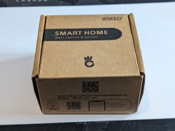
Like a lot of the smart switches, this does require a neutral at the switch.
Unboxing the switch & what is in the box, the first thing I noticed and was impressed with was the mounting plate, it's a strong metal plate, which is a substantial upgrade to a lot of the flimsy plastic housings. Also this is the first switch I have seen using touch panels not springs.
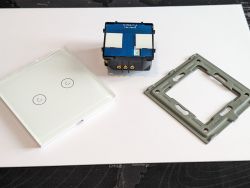
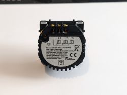
The touch panel pcb is secured in place solely by the 6 pin connector and is easily removed by gently prying around the edges.
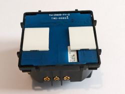
Upon removal of the touch panel pcb, it was revealed that the switch uses the tuya CBU module, so whilst soldering is a possibility, I decided to design and make a solderless jig for the module. The module snaps tightly over the module so does not need holding in place and is readily available here at www.printables.com to download and print (if you don't have access to a 3D printer and want a module sent please PM me)
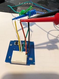
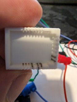
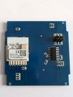
Flashing the module took a few attempts, it would not accept the method of tapping CEN to GND, so I had to revert to removing and reapplying power, this threw various errors and failed but after several attempts the device was read and flashed successfully. In the photo showing the flashing jig and wires in place, the connections are as follows Red(3.3v), Black(Gnd), Green(Tx), White(Rx), Yellow(CEN)
The template for this switch:

Like a lot of the smart switches, this does require a neutral at the switch.
Unboxing the switch & what is in the box, the first thing I noticed and was impressed with was the mounting plate, it's a strong metal plate, which is a substantial upgrade to a lot of the flimsy plastic housings. Also this is the first switch I have seen using touch panels not springs.


The touch panel pcb is secured in place solely by the 6 pin connector and is easily removed by gently prying around the edges.

Upon removal of the touch panel pcb, it was revealed that the switch uses the tuya CBU module, so whilst soldering is a possibility, I decided to design and make a solderless jig for the module. The module snaps tightly over the module so does not need holding in place and is readily available here at www.printables.com to download and print (if you don't have access to a 3D printer and want a module sent please PM me)


Flashing the module took a few attempts, it would not accept the method of tapping CEN to GND, so I had to revert to removing and reapplying power, this threw various errors and failed but after several attempts the device was read and flashed successfully. In the photo showing the flashing jig and wires in place, the connections are as follows Red(3.3v), Black(Gnd), Green(Tx), White(Rx), Yellow(CEN)
The template for this switch:
Code: JSON


Comments
A CBU-based device, nice. CBU is unique among Tuya modules because it has P16 routed out, while CB3S and CB2S don't have it. This device could be hacked to even use a WS2812B LED strip. [Read more]
https://obrazki.elektroda.pl/2529565300_1709139069_thumb.jpg https://obrazki.elektroda.pl/4775507500_1709139069_thumb.jpg https://obrazki.elektroda.pl/5574347100_1709139069_thumb.jpg https://obrazki.elektroda.pl/5727009500_1709139070_thumb.jpg... [Read more]
I've responded via PM regarding the flashing jig. Also, the 6-pin connector is a good place to connect to for power on these boards. Just use a continuity meter to check which pins to use. This makes... [Read more]
@peny11 this may be TuyaMCU device. See the TuyaMCU guide: TuyaMCU flashing, setup and configuration guide - configure dpIDs for Home Assistant Added after 1 [minutes]: You may need to disconnect... [Read more]