
.
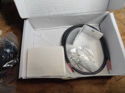
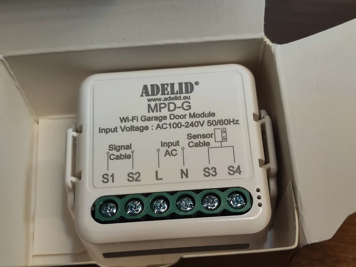
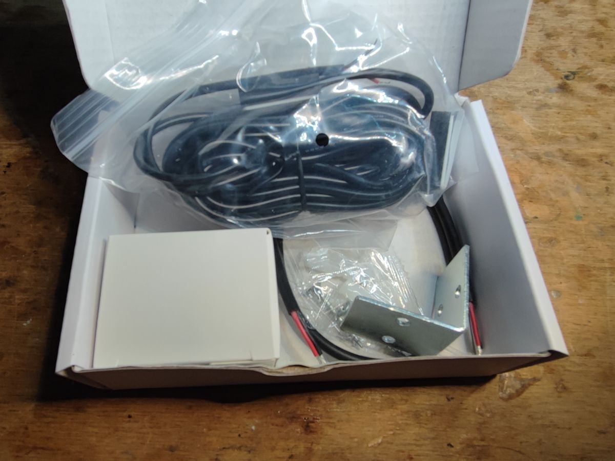
Shown here is a tiny but simple to reprogram garage door controller. The controller shown here normally interfaces with the Tuya cloud and offers door status detection based on an external sensor and the ability to simulate the pressing of a door button via a single voltage-free relay. It is powered by 230V. After
changing the firmware it works without the cloud and is compatible with Home Assistant.
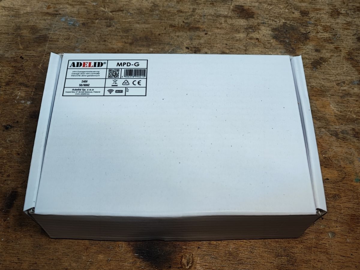
My copy came labelled MPD-G, where G is probably an abbreviation for Gate, although this product goes by different names.

.
The kit still came with an angle bracket and mounting screws:


.
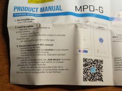
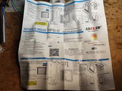
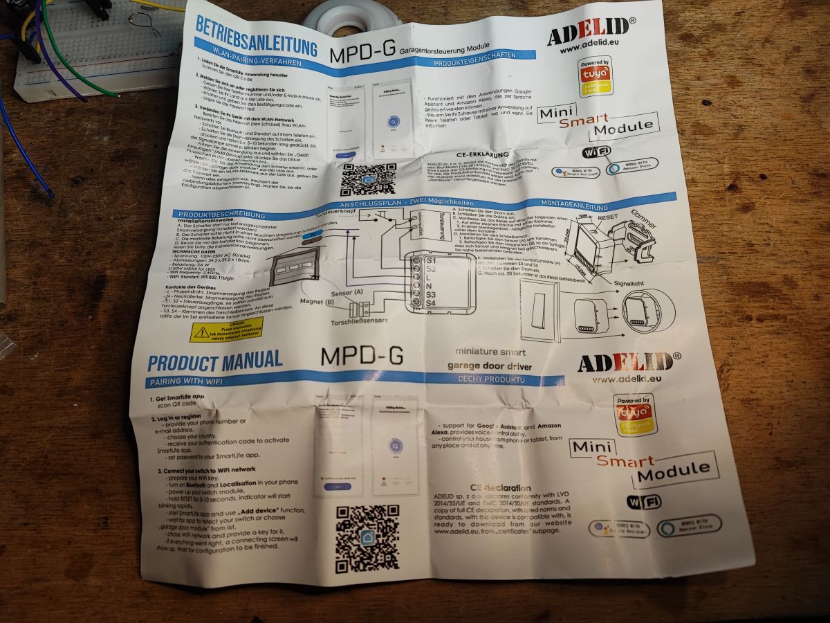
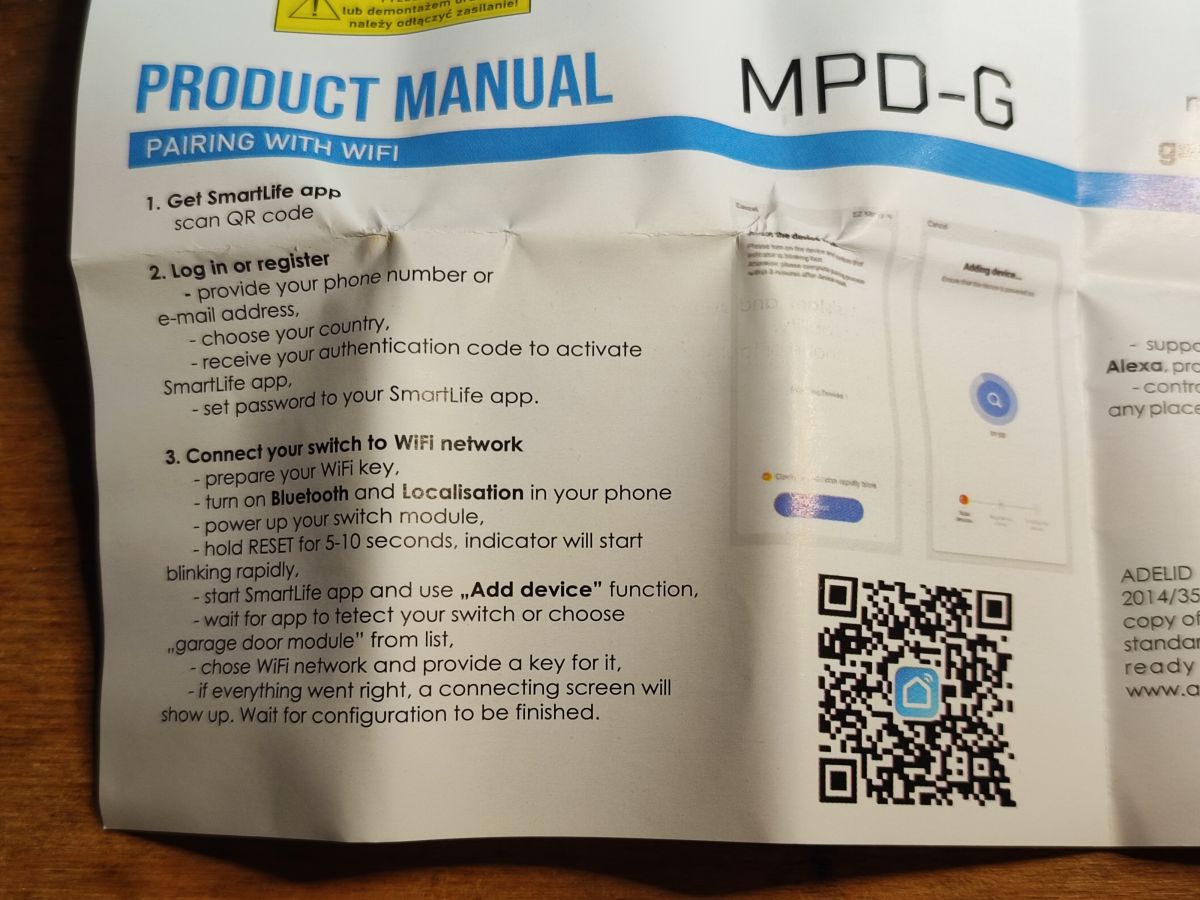
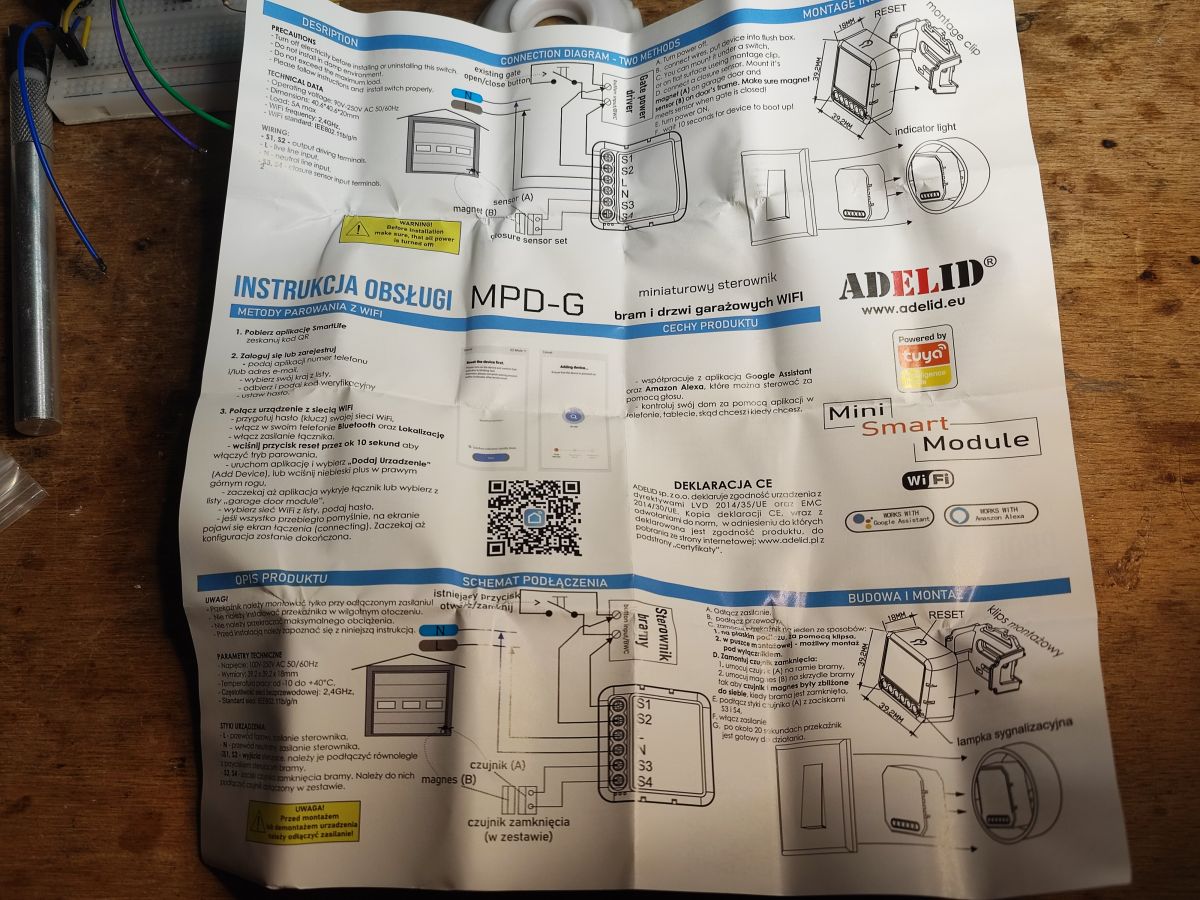
The manual is in several languages, including Polish. It may be of use to someone, it also specifies how to connect the controller to an existing gate controller.

.
However, we are interested in the things that are not found in the manual. Now it is time to look inside.
The casing is a snap-fit. There are no screws in there.

.
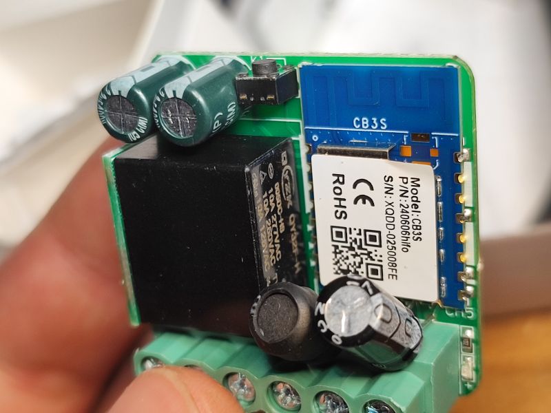
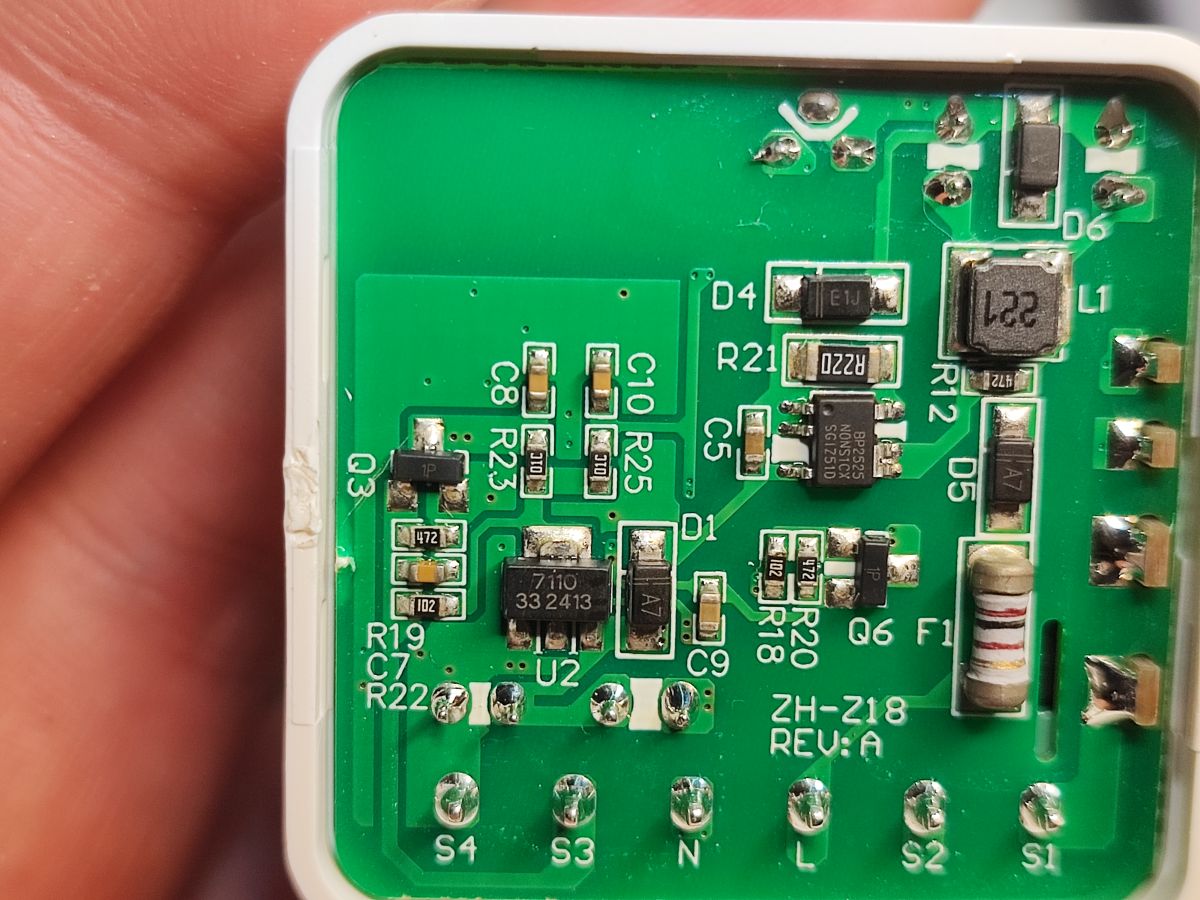
The unit is powered by a non-isolated step-down inverter based on the BP2525. This means that if you break the insulation of the magnetic sensor, there could be mains potential on it. The PCB designation is ZH-Z18 REV:A, and the WiFi module itself is additionally powered by an LDO 7110 33 (3.3V). The PCB also shows Q3 (1P), the transistor that controls the relay.

.
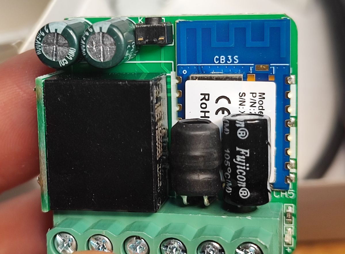
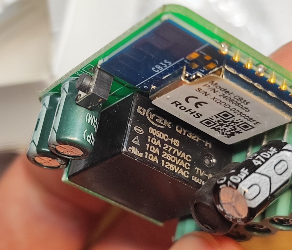
On the other side, we can see the capacitors from the power supply section, the coil from the step-down converter (the one from the mains voltage), and the cleverly placed relay (on the side) with the WiFi module controlling the whole device.

.
This is a CB3S, you can upload Polish firmware to it
OpenBeken .
It's time to change the firmware. You will need a USB to UART converter. We follow the instructions of our flasher:
https://github.com/openshwprojects/BK7231GUIFlashTool
I first whittled down the pads:
.
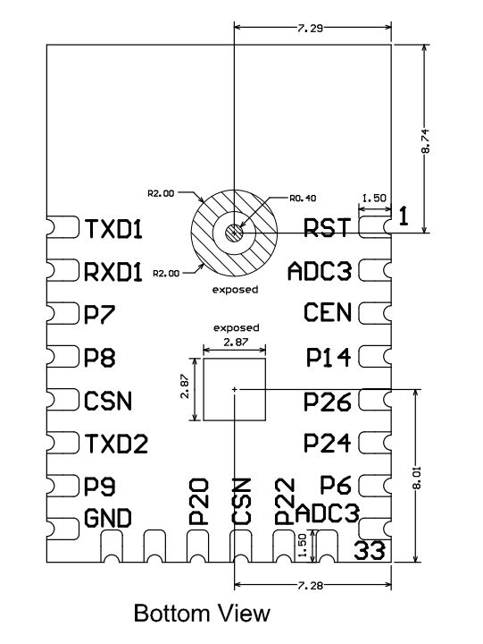
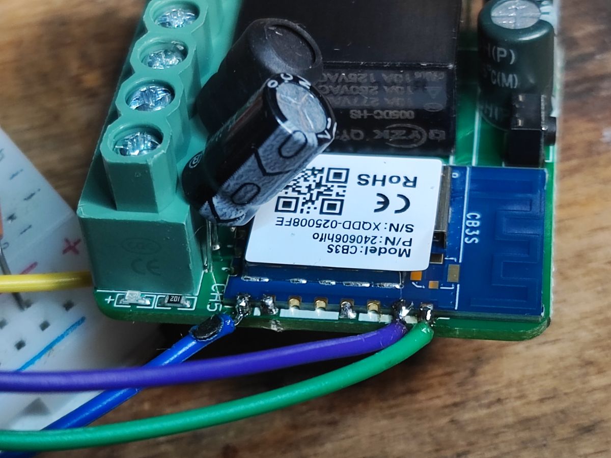
CB3S pad layout (bottom view):
.
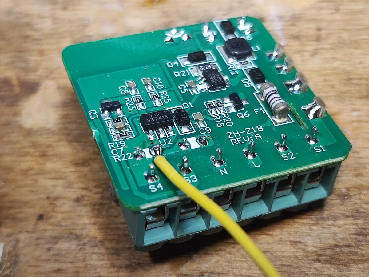
The CB3S power pad was obscured, so I fed the power in differently.

.
There was no problem with the others:

.
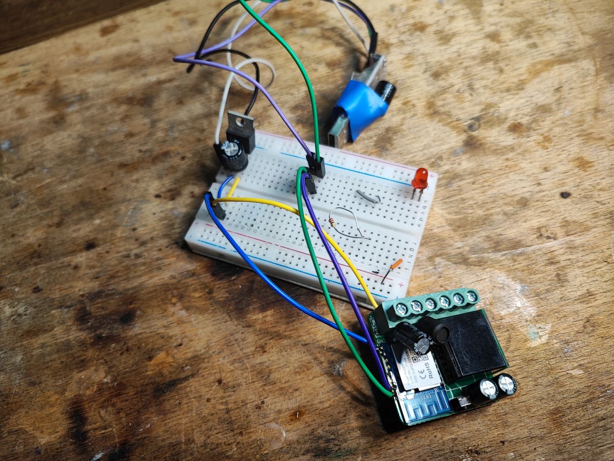
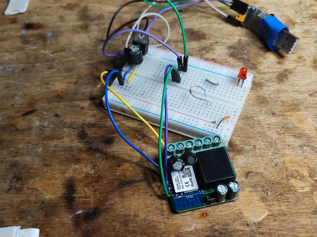
Here is my complete circuit - I had an external LDO from 3.3V:

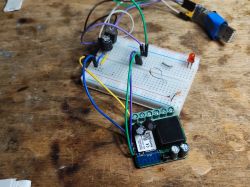
.
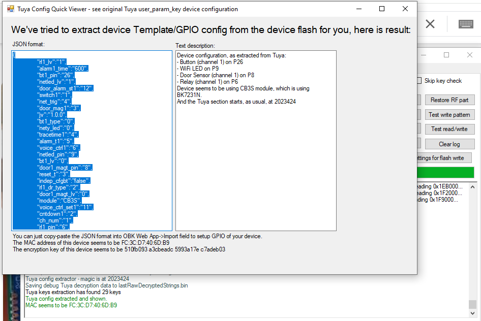
Flasher has correctly detected the GPIO configuration:

JSON Tuya:
.
Verbal description:
Device seems to be using CB3S module, which is BK7231N chip.
- Relay (channel 1) on P6
- WiFi LED on P9
- Door Sensor (channel 1) on P8
- Button (channel 1) on P26
OBK template:
Now you still need to reconfigure the gateway logic. This can be done in HA or in OBK. I will present this at another time, however, if you have any questions, please feel free to write - I will certainly help.
In summary, this was another easy product to reprogram. It can now already open gates in conjunction with Home Assistant, without connecting to the manufacturer's cloud. We can now also configure it freely, for details I invite you to
document the project . For the advanced, there is also the option of programming it in Berry directly on the WiFi module:
Berry scripts for various IoT platforms - OBK scripting tutorial, part 1 .
Which gateway controllers do you use?


Comments
Strange nomenclature, how can a simple WiFi relay be called a gate controller? Gate controllers have various security functions implemented, which are simply missing here. [Read more]
This is simply marketing nomenclature, so that the customer can find the product. It is the same in the situation of roller shutter controllers. There, too, the interior is almost identical to that of... [Read more]