 .
.
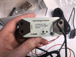
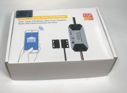
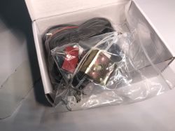
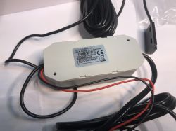
Here I will show a garage door controller that can be easily changed in software so that it works 100% locally, without the cloud, and connects to Home Assistant. Here is the ATLO-GDC2-TUYA, available to buy for just £60. Normally it works with Tuya, but it is built on CB2S, so you can upload our Polish soft to it. All you need for this is a USB to UART converter, but perhaps let's start by looking at the contents of the kit:
 .
.
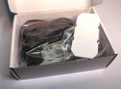
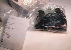
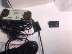
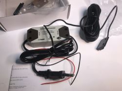
The kit is quite extensive, because in addition to the gate controller itself with the sensor on the long cable, you also get the mounting components, and the whole thing is mains-powered, i.e. it has a built-in power supply. I have already seen kits that required an external power supply fed into the USB port, there is no such problem here.
 .
.
 .
.
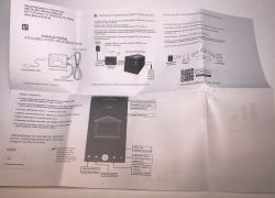
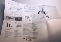
There is also a manual included, which strangely shows a USB powered controller.... perhaps it is the latter version - ATLO-GDC1-TUYA. The manual also describes pairing with an app, which I omit here.
 .
.
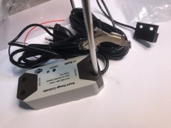
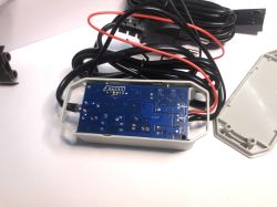
I then move straight on to the presentation of the interior. The screws need to be removed.
 .
.
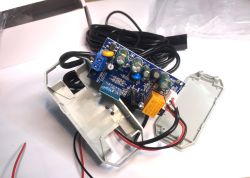
The board is double-sided, but the components are only on the top. It mixes surface mount and through-hole assembly. From the solder side you can see the WiFi module already soldered in.
 .
.
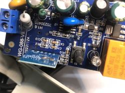
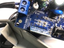
The first impression is positive. A fuse and even a varistor? Apparently these are the basics, but in the cheapest products I often don't see a varistor. Apart from that, there is a non-isolated power supply (step down), a 3.3V LDO, a WiFi module and a relay. The PCB designation is WG-088-V8, date 20230409.
 .
.
The relay (used to short-circuit the gate button) is HUI KE HK4100F-DC5V-SHG.
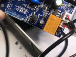
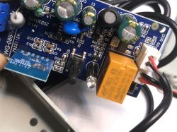 .
.
WiFi module, or CB2S (BK7231N):
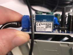
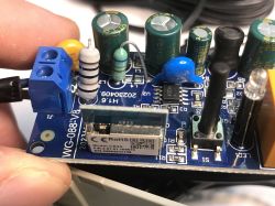 .
.
OBK can be uploaded to it: https://github.com/openshwprojects/OpenBK7231T_App
You will need a USB to UART converter and a 3.3V power supply.
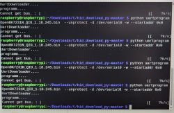
Just use our Flasher: https://github.com/openshwprojects/BK7231GUIFlashTool.
Program according to the flasher readme or according to our Elektroda Youtube videos: https://www.youtube.com/@elektrodacom
We solder the four wires - RX, TX and GND and the power supply (3.3V):
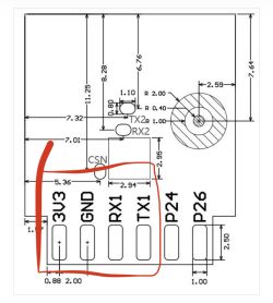 .
.
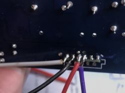 .
.
Here is my whole circuit (with a 3.3V supply, as the device cannot be connected to the mains normally as its power supply does not provide galvanic isolation.... one could make a short circuit and damage the computer).
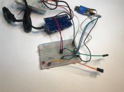 .
.
The mentioned flasher allows to first read the manufacturer's batch and then upload the OBK. In addition, it detects the GPIO configuration:
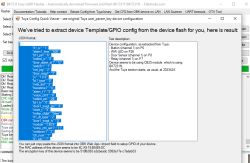 .
.
Tuya configuration:
Code: JSON
You can now use the template converter:
https://openbekeniot.github.io/webapp/templateImporter.html
OBK configuration:
Code: JSON
Verbal description:
Device seems to be using CB2S module, which is BK7231N chip.
- Relay (channel 1) on P7
- WiFi LED on P26
- Door Sensor (channel 1) on P8
- Button (channel 1) on P6
Now you can already freely configure the GPIO as required and/or connect the device to the Home Assistant ( tutorial ). It doesn't have any pre-made interactions at the moment, so it's up to us to decide where and how we script it - it can be done in HA, or in OBK too, via obk or Berry scripts:
https://github.com/openshwprojects/OpenBK7231T_App/blob/main/docs/autoexecExamples.md
Berry scripts for various IoT platforms - OBK scripting tutorial, part 1
Finally, it is probably still possible to write a few words about the operation of this controller itself. The relay on pin P7 is used to simulate pressing the button from opening/closing the gate, it is potential-free. The sensor on P8 allows the current status of the gate to be read out. The button on P6 is the small button for pairing, and the WiFi LED, as you know, shows the status of WiFi. We configure the behaviour of the whole thing as required. Perhaps I will prepare a separate topic, independent of the specific hardware, showing how to configure such a thing.
In summary , the product was with a board dated April 2023, essentially 2 years ago (at the time of writing this topic). Inside was a CB2S (BK7231N) and the firmware change went smoothly. After the conversion, the whole thing is freely configurable and scriptable, as well as linking to Home Assistant. Do you use this type of controller with HA? Feel free to discuss.
Cool? Ranking DIY Helpful post? Buy me a coffee.


