Today, a slightly less typical device, namely the WiFi add-on for controlling the garage door. This device plugs into the existing garage door switch and allows you to remotely close/unlock the garage by briefly shorting the appropriate contacts (simulating a button press). In addition, it offers a simple magnetic sensor put on the gate to check whether it is open. That's all - but it's enough. It's time to see what's inside and change the firmware to free the product from the cloud and from the manufacturer's servers.
Buying a gate controller
I bought the product for about PLN 80. In my opinion, it is quite expensive and we pay more for its function than for electronics. DIY would be much cheaper. When I bought it, it was shipping from the Czech Republic and a slightly different price:

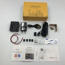
Set contains:
1 x Smart WiFi Garage Door Opener Controller
1 x USB Charging Adapter
1 x USB cable
1 x Manual
1 x Mounting accessories
Photo of the set (according to the seller):

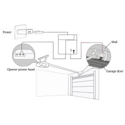
assembly diagram:
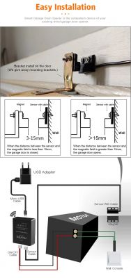
Promotional graphics:


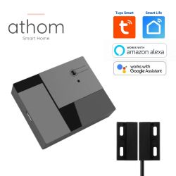
Actual Kit Contents:

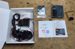
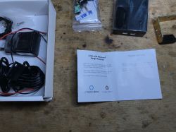

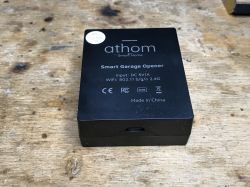
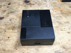
A short test with the Tuya application
As a test, I paired the device with the manufacturer's application. I did the reset by pressing the button from the housing for more than 5 seconds.
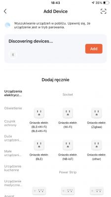
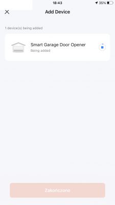
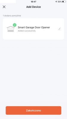
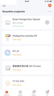
The video shows how it works:
Basically, pressing the button on the housing (or controlling from the app) simply shorts the relay for a short while, simulating pressing the button of the proper gate controller. In addition, an animation appears in the application that the gate is opening, etc. The closing/opening sensor is also supported and is used to show the current state of the gate.
The inside of the gate controller
The plastic housing is held on by hooks. They hold quite solidly, you need to use some force when prying:
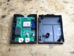
Inside there is a CB3S module, i.e. BK7231N and programming signals.
So you can upload OpenBeken .
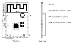
A quote from Tuya publicly available documentation:
Quote:
pin number Symbol I/O type functions 1 RST AND Low-level reset, high level active (the pin has been pulled high internally), correspond to CEN of the IC 2 ADC3 AI ADC pin, which corresponds to P23 of the IC 3 PRICE AND Enabling pin, which is pulled high internally to be compatible with other modules 4 P14 I/O A common GPIO interface, which corresponds to P14 of the IC 5 P26 I/O GPIOP_26, which corresponds to P26 of the IC, PWM 5 6 P24 I/O GPIOP_24, which corresponds to P24 of the IC, PWM 4 7 P6 I/O GPIOP_6, which corresponds to P6 of the IC, PWM 0 8 VCC P Power supply pin (3.3V) 9 GND P Power supply reference ground 10 P9 I/O GPIOP_9, which corresponds to P9 of the IC, PWM 3 11 TXD2 I/O UART2_TXD (used to display the module internal information), which corresponds to P0 of the IC 12 CSN I/O Production test control pin. If it is used as a common I/O pin, it must be connected to the VCC externally. Do not connect it to the ground before the module is powered on. 13 P8 I/O GPIOP_8, which corresponds to P8 of the IC, PWM 2 14 P7 I/O GPIOP_7, which corresponds to P7 of the IC, PWM 1 15 RXD1 I/O UART1_RXD (user serial interface), which corresponds to P10 of the IC. Do not connect it to the VCC. By default, the MCU serial port should be in low-level or high-impedance state. 16 TXD1 I/O UART1_TXD (user serial interface), which corresponds to P11 of the IC. Do not connect it to the VCC. By default, the MCU serial port should be in low-level or high-impedance state. 17 ADC3 AI (Not recommended. If needed, please use Pin 2) ADC port, which corresponds to P23 of the IC. Programmed SPI 18 P22 I/O (Not recommended ) GPIOP_22, which corresponds to P22 of the IC. Programmed SPI 19 CSN I/O The pull-up resistor is needed during usage of customers. Do not connect it to the ground before the module is powered on. Correspond to P21 of the IC. 20 P20 I/O (Not recommended. ) GPIOP_20, which corresponds to P20 of the IC. Programmed SPI 21 NC - - 22 NC - -
I only use TXD1 and RXD1 for programming. But first we will see the rest of the PCB:
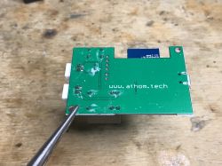
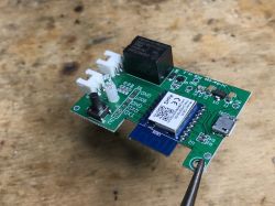
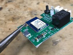
Basically on the PCB we have:
- LDO AMS1117 (gives us 3.3V for WiFi module with 5V)
- small button and LED
- connector for the button from the garage (with a relay, this relay shorts them and simulates pressing)
- connector for gate opening/closing sensor
The role of BK7231 pins:
- P7 - relay (the one that turns on the right gate)
- P8 - gate opening/closing sensor input
- P24 - LED from the board
- P26 - button from the board
ADVERTISEMENT
programming procedure
Programming this particular BK7231 will be very simple.
All you need is a USB to UART converter with 3.3V voltage levels. Solder three wires - ground, RX and TX.
Then we run the program on the computer (bkWriter 1.60, or better, hid_download_py) and when you need to RESET the system, simply disconnect the USB cable from the connector on the board. We just reboot.
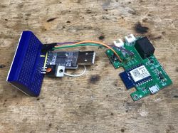
Thanks to this, you do not need to solder this "BOOT" signal or an additional 3.3V LDO, because it is already on board.
https://github.com/OpenBekenIOT/hid_download_py
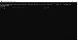
This is BK7231N, so we upload the QIO binary to offset 0. If it was BK7231T, we would upload UA to the default offset. As in OpenBK Readme.
OpenBeken configuration
First, set the pins, the ones I gave above in the table.
We will assume that channel 0 controls the relay and channel 1 is the door status reading.
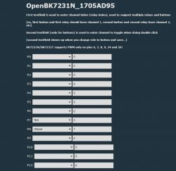

The dInput input type used for the door sensor is simply digital input - it sets the given channel to the value taken from the digital pin.
Then we do cosmetics - set the type of channel 1 as "OpenClosed" to display the status of the door in text (and not as a number):
setChannelType 1 OpenClosed
Then you should add something that, like the original firmware, will "disconnect" the relay back - so as to generate a short pulse. Just write a simple event handler in OpenBeken, all fully scriptable:
addChangeHandler Channel0 != 0 addRepeatingEvent 2 1 setChannel 0 0
When channel 0 changes its value to non-negative (then the relay will also close automatically), we start the 2-second timer with 1 repetition, after which we set channel 0 to 0 (this will open the relay).
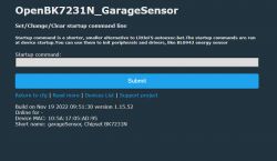
The above scripts should be entered in LittleFS in autoexec.bat or in "Short startup command" together with the backlog:
backlog setChannelType 1 OpenClosed; addChangeHandler Channel0 != 0 addRepeatingEvent 2 1 setChannel 0 0
that is here:
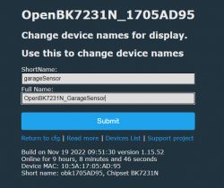
It's also worth changing the name to something more meaningful:
Home Assistant setup - step 1
The first stage of configuration requires adding separately the relay control (as a switch) and the sensor reading (as a binary_sensor) to Home Assistant. We will use YAML code for this purpose. We have to remember what channels we assigned to given roles - here we receive them by the MQTT subject from get and set them by the MQTT subject from set. as below:
Code: YAML
The above Yaml defines a garage opening sensor. We only have "state_topic" from get here, which means we receive what OBK publishes.
Now handling the relay:
Code: YAML
As above, only "command_topic" is added, i.e. a topic that allows us to send a new state of the relay to OpenBeken.
The above Yaml should give us:
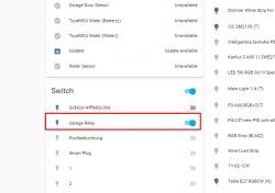
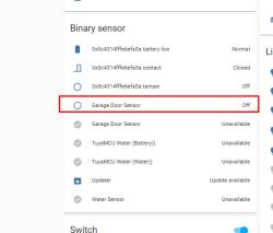
The above sensor on the HA interface should react to a change in the state of the sensor on the device, as it should be possible to control the relay from the HA level!
Home Assistant setup - step 2
Now we will use the mechanism cover in order to connect our opening sensor and relay (scripted in OBK so that it returns to the open state after a while) into a whole.
cover documentation:
https://www.home-assistant.io/integrations/cover/
Here is the finished code:
Code: YAML
What do you need to know here?
- binary_sensor.garage_door_sensor_2 points to our garage sensor
- switch.garage_relay points to our relay
The same could be done with a regular relay (separately) and a door open/close sensor (separately).
The above code only calls switch.turn_on because the relay disconnects itself afterwards (script Obk).
Blocks with if allow you to choose the icon and the value of the gate.
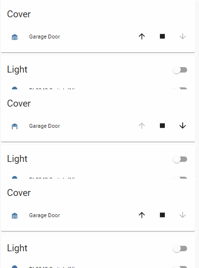
The stop button does nothing at the moment.
Summary
This device is really very simple - it's strange that it costs so much. It would be much cheaper to make a similar mechanism yourself, even on a cheap ESP8266.
Changing the CB3S firmware also went without problems - as well as configuration in Home Assistant.
Unfortunately, in practice (on a real gateway) I did not test the device, because I did not have access to such a luxury, but "dry" tests showed that after changing the firmware and with HA everything works. And if anything, you can always change the behavior of the software - even script it differently or organize the operation in Home Assistant differently.
Does anyone on the forum have a garage door controlled by WiFi, and paired with HA?
Feel free to comment.
Cool? Ranking DIY Helpful post? Buy me a coffee.


