[BK7231T / WB3S] Makegood MG-AUWF01 "Touch WiFi Wall Socket" Revision 1.2-211019
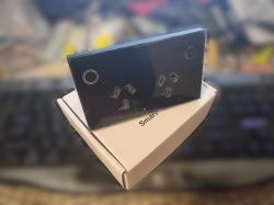
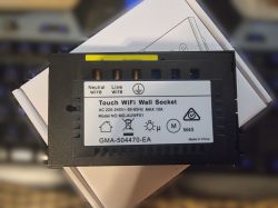
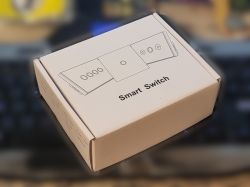
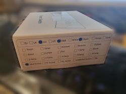
I had previously bought a set of these around 2020 because they contained an ESP-12F with Tasmota support. later I bought some more, but they changed the chip used in them. Thankfully I've found people have been making a similar firmware for this board as well. There's no guide for this particular device however, but I can use this as an opportunity to contribute something!
I had only used tuya-convert before, so this was a bit of a learning curve, but actually doing the modification was not difficult once you've figured it out. once i'd done one of them, the rest took less than 5 minutes each.
--
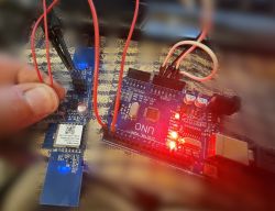
Here's what i ended up doing for most of them. initially I soldered all four wires (VCC/GND/TX/RX), but later I used cheap probes for the power (could do wire wrapping instead), and just held the TX/RX by hand (no soldering!). Using a clone Arduino UNO held in reset in place of a USB to TTL serial adapter. I used the BK7231 Easy UART Flasher tool, running it under linux using mono. A baud rate of 460800 was consistent for me. I simply held the serial wires in place, clicked the read/write button in the flasher tool, then plugged in the VCC pin to the Arduino.
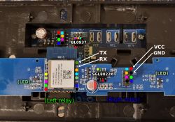
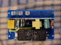
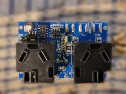
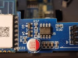
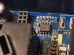
Here's some photos of the boards:


--
Configuration:
Pins;
"pins": {
    "1": "LED_n;2;0",
    "6": "Rel;1;0",
    "7": "Rel;2;0",
    "8": "BL0937CF1;1;0",
    "9": "BL0937CF;2;0",
    "11": "Btn;1;1",
    "14": "Btn;2;2",
    "24": "BL0937SEL;2",
    "26": "LED_n;1"
  },
Note: original firmware had the LEDs red when on and blue when off. I don't find this natural, so I've swapped this behaviour. If you prefer the original behaviour, use "LED" instead of "LED_n".
Under "Configure Startup", I set both channels to "-1" so it would remember switch state upon power loss.
Under "Configure General/Flags", I set "Flag 6 - [BTN] Instant touch reaction instead of waiting for release (aka SetOption 13)". otherwise touch buttons will only be on when held.
Here are original firmwares for the devices. one plain file, and an archive of 20 firmwares (including the plain one attached). They're all from the same shipment, so should contain only differences unique to each device. They were not activated/used with the intended app/service beforehand.
--
AI: Just to clarify, are you looking for help with anything specific regarding flashing or configuring the MG-AUWF01 sockets, or are you mainly sharing your experience for others?
Sharing how to get OpenBeken installed and configured on it.
AI: Did you run into any issues or unexpected behavior during the flashing or setup process that you’d like advice on?
A general explanation of how to configure OpenBeken for a new device would be nice. I spent some time figuring out how the pin numbers in OpenBeken correlated with the board I have, before realising the pin numbers are for the Beken chip itself, so I basically had to ignore them and use the names for the pins only (except pin 14 which was just pin 14). I also didn't learn OpenBeken had tools to detect and test pins within its' UI before I had already worked it out by tracing/beeping out each pin with a multimetre


Comments