logo elektroda
logo elektroda
X
logo elektroda

[CB2S/BK7231N] Flashing AVATTO WiFi Smart Socket with BK7231 Easy UART Flasher

enochbryant2 1428 7
ADVERTISEMENT
  • Helpful post
    #1 20858931
    enochbryant2
    Level 3  
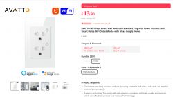
    Image of an AVATTO WiFi Tuya wall socket with a power monitor.
    Product specifications table from AliExpress.
    https://www.aliexpress.us/item/32568045880987...US%213489641176%21&curPageLogUid=fc42pj50kRIv

    Got these in today and found out they have the C2BS chips. First time messing with openbeken, have to say it was pretty simple.

    With these, after taking it apart and clamping on the mini alligator clips, I was able to flash with ease. Once you open BK7231 Easy UART Flasher, select the N chip. I left the default flash file it loads when you start the program, wanted to make sure OTA update worked after.
    When it says Getting bus... (now, please do reboot by CEN or by power off/on) all I did was hold both power buttons (black buttons) at the same time for close to 10 seconds. The flash program detected it and flashed away.

    Below is the extracted data

    Device configuration, as extracted from Tuya:
    - Button (channel 1) on P24
    - WiFi LED on P23
    - Relay (channel 2) on P7
    - Button (channel 2) on P26
    - Relay (channel 1) on P6
    Device seems to be using CB2S module, which is using BK7231N.
    And the Tuya section starts, as usual, at 2023424

    and json data
    Code: JSON
    Log in, to see the code


    After rebooting the device, I was able to access the UI page and configure MQTT, showed up quickly in HA. This device does have 2 LEDs for each switch and also has energy monitoring when I had it added in smart life.

    I have found no devices like it to apply a configuration profile and I am unsure how to set all that up. Would it be possible to get help from the community to get this configured correctly?

    Much appreciated!!!!
  • ADVERTISEMENT
  • #2 20866062
    p.kaczmarek2
    Moderator Smart Home
    Hello, is this device using BL0942? Maybe you could try doing:
    
    startDriver BL0942
    

    for a start. Have you tried to look inside it?
    Helpful post? Buy me a coffee.
  • ADVERTISEMENT
  • #3 20867385
    enochbryant2
    Level 3  

    That worked, and I was able to apply calibration.

    How do I start that driver on reboot?
  • #4 20867401
    p.kaczmarek2
    Moderator Smart Home
    You can either put this in a short startup command (in Options) or in autoexec.bat in LittleFS:


    Helpful post? Buy me a coffee.
  • ADVERTISEMENT
  • #5 20867452
    enochbryant2
    Level 3  

    Perfect, got that. TYVM!

    Few other questions.

    This plug has 2 LEDs under the power buttons for outlet 1 and outlet 2. I used the GPIO finder but cannot seem to locate which GPIOs are the LEDs to change colors.

    Screenshot of a smart device configuration interface. Visible GPIO list and MQTT settings.

    The other question is getting all of these config pieces into MQTT. Currently, all I have showing in MQTT is RSSI.
  • ADVERTISEMENT
  • #6 20867652
    p.kaczmarek2
    Moderator Smart Home
    Why do you have current_div channels?


    Do you know that you need to retry HASS discovery after changing config?

    Your relays should be properly discovered by HA
    Helpful post? Buy me a coffee.
  • #7 20867774
    enochbryant2
    Level 3  

    I cleared out the current_div and also found out how to start the HA discovery, this is what I have now. Since it sees 2 switches, is it possible to see different amps for each outlet? I stumbled across this post https://www.elektroda.com/rtvforum/topic3887748.html and thought adding the sensor mqtt in config.yaml would show it, but it doesn't. Also any idea on the LEDs for the buttons? I'd like to change them to red when they are off.
  • #8 20868217
    p.kaczmarek2
    Moderator Smart Home
    enochbryant2 wrote:
    Since it sees 2 switches, is it possible to see different amps for each outlet?

    In the 99% of devices it is not possible. Do you have a single BL0942 inside, or two BL0942? Does the current driver for BL0942 shows power for both outlets together? If so, then it's not possible by design.

    In such cases it's often worth to check what Tuya app could do so we can reasonably know what to expect after firmware change.

    enochbryant2 wrote:

    Also any idea on the LEDs for the buttons? I'd like to change them to red when they are off.

    Again, considering that there is no mention about extra LEDs in JSON, and that you've found none of them with GPIO Doctor, I would say it's not possible and the LEDs are hardwired to buttons. Of course, if you were to open the device case, then you could easily reroute LEDs to the unused GPIOs and script them any way you want to. That would require a bit of soldering (and making jumpers from wires), but would work
    Helpful post? Buy me a coffee.

Topic summary

The discussion revolves around flashing the AVATTO WiFi Smart Socket equipped with BK7231N chips using the BK7231 Easy UART Flasher. The user successfully flashed the device and sought assistance with configuring the BL0942 driver for calibration and MQTT integration. Subsequent queries included identifying GPIOs for LED control and the possibility of monitoring individual outlet amperage. Responses indicated that the device likely contains a single BL0942 chip, limiting the ability to track separate outlet power. Suggestions included checking the Tuya app for functionality insights and potential hardware modifications for LED control.
Summary generated by the language model.
ADVERTISEMENT