logo elektroda
logo elektroda
X
logo elektroda

Spectral Clock - Propeller Clock

mb1988  239 390380 Cool? (+35)
📢 Listen (AI):

TL;DR

  • A Spectral Clock propeller clock uses a spinning LED rotor to display time.
  • An ATMEGA32 controls 32 blue SMD LEDs through four MBI5170 drivers, takes time from a DS1307 RTC over I2C, and uses an optoelectronic sync sensor.
  • The controller’s 32 KB flash supports multiple display modes.
  • An HDD motor with a PHILIPS TDA5140A driver spins the propeller; the motor winding’s triangle connection required an artificial center point and brush power.
  • A 15 mm plexiglass case keeps noise low at 50 revolutions per second, but the documentation still has flaws and was not yet fully released.
Generated by the language model.


At the beginning I would like to say hi, because as you can see this is my first post. I've been browsing the electrode for a long time, but I've never been on the forum. Today I decided to take a step forward, show myself with something specific.

The idea of the project is as old as the world, repeatedly rolled out on the forum. Nevertheless, I would like to show my implementation of this idea.

The system consists of two main parts: a programmable propeller and a drive part.

==============================
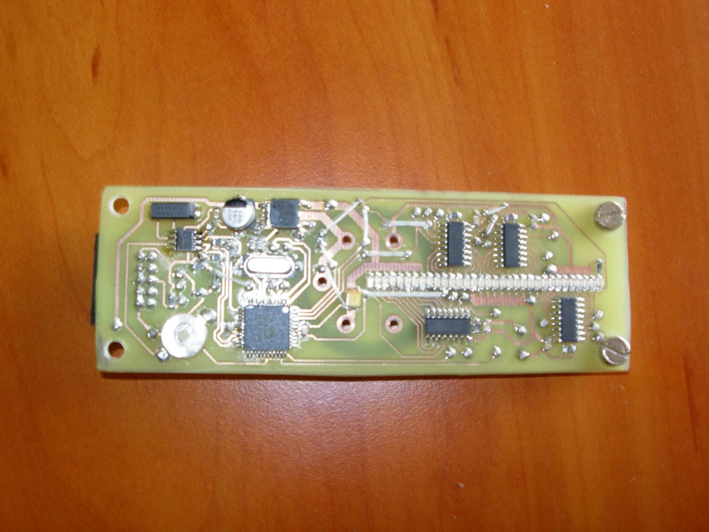
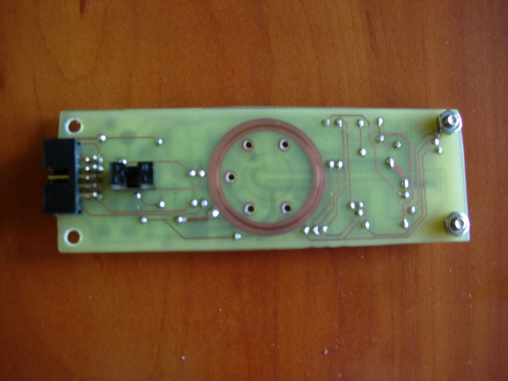
:arrow: Propeller:


The heart of the system is the ATMEGA32 microcontroller that manages the display content. It drives 32 blue smd diodes via 4 serial LED MBI5170 drivers. The time is taken from the RTC DS1307 system, with the uC it is connected by the I2C bus. Image synchronization is of course realized by an optoelectronic sensor. 32 KB of flash memory in ATMGA allow support for multiple display modes.
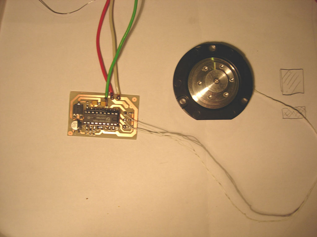

:arrow: Engine:


I tried many solutions and the HDD motor turned out to be the best. It works almost silently, has a high speed of rotation, 6 threaded holes for easy attachment of the propeller. The use of such an engine, however, was associated with the use of a special control. The optimal solution seemed to be the use of a dedicated PHILIPS TDA5140A driver working in the standard configuration (although not entirely, because the winding in the motor is connected by a triangle, so it was necessary to create a point of an artificial center). Energy is transported by brushes. I am aware of the imperfections of such a solution, but I did not want to complicate the project further. In this matter, I leave the door open to designing the next version.
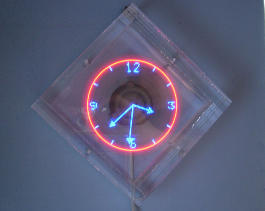
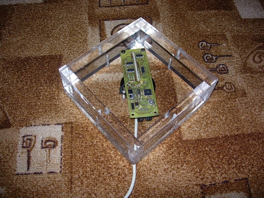

:arrow: Case:


As you can see, the casing is made of 15 mm plexiglass. Such thick walls mean that at 50 revolutions per second, the noise level produced by the clock is kept at a very decent level. Additionally, if something inside should be broken by accident, no one in the vicinity of their heads will lose their heads. The back cover is fixed with 4 screws, the rest of the structure is glued with ACRIFIX 192 glue.

As I am not a professional, the documentation created during the production of the clock has many flaws, so I am not enclosing it yet. I will try to refine it a bit and then post it on the forum.

I am open to any suggestions regarding the project.

Below is a link to a video showing the clock's work:

http://pl.youtube.com/watch?v=no2_M_b059g " target="_blank" rel="nofollow noopener ugc" class="postlink inline" title="" > http://pl.youtube.com/watch?v=no2_M_b059g

========
I added documentation. I apologize in advance for any shortcomings.

Regards
mb1988
Attachments:
  • source.rar (220.61 KB) You must be logged in to download this attachment.
  • BLCD Driver.rar (49.67 KB) You must be logged in to download this attachment.
  • PropClock_v2.rar (240.1 KB) You must be logged in to download this attachment.

About Author
mb1988
mb1988 wrote 93 posts with rating 258 . Been with us since 2006 year.

Comments

lucas_mcs 17 Feb 2008 16:30

Great project, I'm trying to do one myself, could you say something more about the HDD motor control? [Read more]

mb1988 17 Feb 2008 16:38

At the beginning, I thought that I would build a driver myself that would be able to drive such an engine well. However, as it turned out later, handling all this electronic commutation is not that simple.... [Read more]

Freddie Chopin 17 Feb 2008 17:44

in what language did you write the prock program? 0x41 0x56 0x45 !! [Read more]

mb1988 17 Feb 2008 17:50

All written in C. [Read more]

Anonymous 17 Feb 2008 18:40

Very nicely. I wouldn't do it myself. the movie is knocking down. Probably the C program is very complicated. I am waiting impatiently for more material on this watch. [Read more]

Uszol 1990 17 Feb 2008 18:43

:D Hello elegant design :D extra movie :) I like the square the most and YouTube at the end. :) really cool :) greetings ps. Can you count on the code and pcb? [Read more]

mb1988 17 Feb 2008 18:48

Of course, just like I mentioned, I have to bring him to a state where he can be shown to someone :P . [Read more]

Uszol 1990 17 Feb 2008 19:08

one more question How did you balance it that it works so perfectly? did you have a lot of work with it? [Read more]

lucas_mcs 17 Feb 2008 19:24

It is probably not a matter of balance, but that it is mounted so firmly, and finally the HDD motor is quite strong. I still have a question, what is the display synchronization with this optoelectronic... [Read more]

Twizzter 17 Feb 2008 19:43

I am impressed, the structure is well designed and how effective! ;) You have to admit that you have skills when it comes to programming, and in spectral clocks the issue of software - as you can see in... [Read more]

mithcrist 17 Feb 2008 19:44

Awesome ... respect :D I have one question: could it be used instead of a HDD motor with a larger computer fan, e.g. 12cm? I would make such a watch myself, but I do not have such manual skills, I would... [Read more]

mb1988 17 Feb 2008 20:05

There is a lot of truth to this. The propeller is bolted in several places and, in addition, the engine has such a compact structure that I have the impression that the car could run over it. Nevertheless,... [Read more]

pawelj 17 Feb 2008 20:30

I salute my friend. Revelation. The video makes an amazing impression. The execution is also such that there is nothing to cling to. A beautiful thing [Read more]

Dariusz Goliński 17 Feb 2008 20:59

Very nice construction. Write whether the big problem is the use of graphics in the project. The one you presented is a revelation for me, I have not come across a clock displaying such graphics. What... [Read more]

mb1988 17 Feb 2008 21:15

The graphics weren't much of a problem. Writing a simple C ++ converter from a monochrome bitmap to something that I can upload to the prock was a matter of one evening of tapping. The rotating cube... [Read more]

HakuS492 17 Feb 2008 21:56

It looks great :P but I wonder how long this ring which is a contact for brushes will last :) maybe it would be possible to cover it with something until it wears off, it seems to me that from time to... [Read more]

Twizzter 17 Feb 2008 22:40

Once, probably on YouTube, a movie was shown showing interesting rims - pimpstar. The idea was based on a spectral display, but it consisted of three light lines, additionally equipped with multi-colored... [Read more]

marcindc 17 Feb 2008 22:53

I have to congratulate you because the whole structure is of a very high standard !! I wanted to do something similar myself, but so far it is beyond my strength. I would also be interested in the cost... [Read more]

lisek1988 17 Feb 2008 22:55

I'm really in awe ... think you're my age :) SHOCKING... I just wonder how much this copper, which is in contact with the circle, will last, because you can see that it is already a bit worn... [Read more]

FAQ

TL;DR: One Propeller-Clock rotor spins 50 rps (≈3 000 rpm) while an ATmega32 drives 32 LEDs; “in spectral clocks the issue of software … can make a difference” [Elektroda, Twizzter, post #4815839] Size, speed and code tweaks decide image quality. Why it matters: these tips prevent the common “00:00:80” bug and burnt HDD motors.

Quick Facts

• Rotor speed: 45-55 rps recommended to avoid flicker [Elektroda, mb1988, post #4814890] • Power draw: 5 V / 250 mA (motor), 12 V / 80 mA (LEDs) [Elektroda, mb1988, post #4816959] • LED count: 32 SMD on radius = 63 pixels diameter [Elektroda, mb1988, post #4815891] • Motor driver: Philips TDA5140A; drop-in LB1688 works with minor tuning [Elektroda, mb1988, post #4815034] • Typical build cost: PLN 50–60 for electronics; case from scrap plexi [Elektroda, mb1988, post #4816863]

How do I wire and start an HDD spindle motor for a propeller clock?

Use a three-phase BLDC driver such as TDA5140A in the page-9 reference design; tie the three windings to MOT1-MOT3 and create an artificial center if the drive is delta-connected [Elektroda, mb1988, post #4815034] Feed 5–6 V to VLOGIC and 5–12 V to VMOT while monitoring temperature.

Why does my DS1307 show 00:00:80 instead of real time?

Bit 7 of the seconds register (CH) is still high; the oscillator is halted. Clear CH once, then save time. Many builders forget the pull-up on SQW, causing the same symptom [Elektroda, mb1988, post #7122854]

What fuse settings are needed on the ATmega32?

Enable external 16 MHz crystal, start-up 16K CK+65 ms, CKOPT unprogrammed. Leave JTAGEN off to free PORT C pins. Wrong fuses keep INT0 from firing and the display stays blank [Elektroda, hetm4n, post #12007461]

How can I balance the spinning PCB without special tools?

Screw the board firmly to the motor hub, then eyeball component placement symmetrically. If vibration persists, add small blobs of epoxy opposite heavy parts until the wobble stops [Elektroda, mb1988, post #4815891]

What’s the simplest way to set or change time?

  1. Compile firmware with the desired compile-time constant (e.g., 12:00). 2. Flash it exactly at that wall-clock moment. 3. Immediately flash the normal firmware that leaves RTC untouched. This two-step trick was used by the original author [Elektroda, mb1988, post #4817605]

Can I replace the 8-bit MBI5170 LED drivers?

Yes. Any constant-current shift register (e.g., STP08DP05, 74HC595 + resistors) works if you adjust SPI width in code. One builder ran three ST16CP05 without issues [Elektroda, Scyzor, post #7800620]

My image drifts; how do I sync display to speed?

Reset TIMER1 on each opto-interrupt, divide the measured period by 240, load that into TIMER0; update LEDs in the TIMER0 ISR. If drift persists, lower the prescaler so division error stays <0.5 µs [Elektroda, mb1988, post #4815891]

What causes a missing wedge or duplicate sector in the graphics?

Integer rounding of TCNT1/RESOLUTION leaves residue; the wedge shifts with RPM. Use 32-bit math or accumulate fractional ticks (phase accumulator) to eliminate the gap [Elektroda, Pawełmatrix, post #4820097]

How do I convert bitmaps or GIF frames to the 960-byte frame table?

Crop a 63 × 63 monochrome bitmap, iterate every 1.5°, sample radius 0-31, and store four bytes per ray (240 steps × 4 = 960 bytes). Community GUI converters are shared in the thread [Elektroda, boxochi, post #17138028]

What’s a safe current for the SMD LEDs?

Set the MBI constant-current to 20–25 mA; with 50 rps the duty cycle is ~0.4 %, so average LED current stays below 100 µA, preventing thermal stress [MBI datasheet].

Edge case: my motor only starts if I spin it by hand—fixes?

Increase VMOT to 7–9 V, swap two phase wires, and check that CAP-CD/CAP-DC pins have the exact values (22 nF chosen wrong cuts starting torque) [Elektroda, Moyshaa, post #9075908]

Can I power the board contact-less to avoid worn brushes?

Yes. Wind a 3-turn primary under the plexi base and a 6-turn secondary on the rotor; resonate near 35 kHz. Keep coils 5 mm above the aluminum hub to curb eddy-current heating [Elektroda, mlassota, post #7122363]

Step-by-step: flashing firmware and storing graphics

  1. Flash boot HEX with CH cleared. 2. Flash main HEX. 3. Use the provided PC tool to convert BMP/GIF to EEPROM HEX, then flash EEPROM. Done.

What’s the expected lifetime of the brushes?

Copper ring runs for 1–2 years at 50 rps before visible wear; lowering speed to 25 rps triples life, according to a 10-year user report [Elektroda, hetm4n, post #19746865]
Generated by the language model.
%}