Elektroda.com
Elektroda.com
X

Spectral Clock - Propeller Clock

mb1988 379832 239
This content has been translated flag-pl » flag-en View the original version here.
  • Spectral Clock - Propeller Clock

    At the beginning I would like to say hi, because as you can see this is my first post. I've been browsing the electrode for a long time, but I've never been on the forum. Today I decided to take a step forward, show myself with something specific.

    The idea of the project is as old as the world, repeatedly rolled out on the forum. Nevertheless, I would like to show my implementation of this idea.

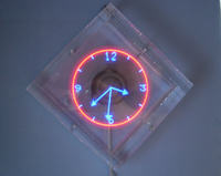
    The system consists of two main parts: a programmable propeller and a drive part.

    ==============================
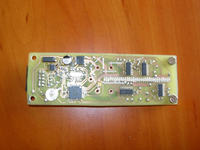
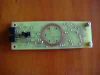
    :arrow: Propeller:

    Spectral Clock - Propeller Clock Spectral Clock - Propeller Clock

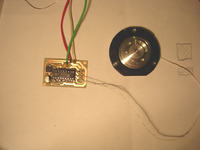
    The heart of the system is the ATMEGA32 microcontroller that manages the display content. It drives 32 blue smd diodes via 4 serial LED MBI5170 drivers. The time is taken from the RTC DS1307 system, with the uC it is connected by the I2C bus. Image synchronization is of course realized by an optoelectronic sensor. 32 KB of flash memory in ATMGA allow support for multiple display modes.
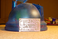
    :arrow: Engine:
    Spectral Clock - Propeller Clock Spectral Clock - Propeller Clock

    I tried many solutions and the HDD motor turned out to be the best. It works almost silently, has a high speed of rotation, 6 threaded holes for easy attachment of the propeller. The use of such an engine, however, was associated with the use of a special control. The optimal solution seemed to be the use of a dedicated PHILIPS TDA5140A driver working in the standard configuration (although not entirely, because the winding in the motor is connected by a triangle, so it was necessary to create a point of an artificial center). Energy is transported by brushes. I am aware of the imperfections of such a solution, but I did not want to complicate the project further. In this matter, I leave the door open to designing the next version.

    :arrow: Case:

    Spectral Clock - Propeller Clock

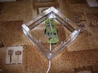
    As you can see, the casing is made of 15 mm plexiglass. Such thick walls mean that at 50 revolutions per second, the noise level produced by the clock is kept at a very decent level. Additionally, if something inside should be broken by accident, no one in the vicinity of their heads will lose their heads. The back cover is fixed with 4 screws, the rest of the structure is glued with ACRIFIX 192 glue.

    As I am not a professional, the documentation created during the production of the clock has many flaws, so I am not enclosing it yet. I will try to refine it a bit and then post it on the forum.

    I am open to any suggestions regarding the project.

    Below is a link to a video showing the clock's work:

    http://pl.youtube.com/watch?v=no2_M_b059g " target="_blank" rel="noopener nofollow ugc" title="http:// http://pl.youtube.com/watch?v=no2_M_b059g " class="postlink inline-block "> http://pl.youtube.com/watch?v=no2_M_b059g

    ========
    I added documentation. I apologize in advance for any shortcomings.

    Regards
    mb1988

    Cool? Ranking DIY
    About Author
    mb1988
    Level 12  
    Offline 
    mb1988 wrote 93 posts with rating 256. Been with us since 2006 year.
  • #2
    lucas_mcs
    Level 22  
    Great project, I'm trying to do one myself, could you say something more about the HDD motor control?
  • #3
    mb1988
    Level 12  
    lucas_mcs wrote:
    Great project, I'm trying to do one myself, could you say something more about the HDD motor control?

    At the beginning, I thought that I would build a driver myself that would be able to drive such an engine well. However, as it turned out later, handling all this electronic commutation is not that simple. Then I decided to use this layout (http://www.ortodoxism.ro/datasheets/philips/TDA5140A_2.pdf " target="_blank" rel="noopener nofollow ugc" title="http:// http://www.ortodoxism.ro/datasheets/philips/TDA5140A_2.pdf " class="postlink inline-block "> http://www.ortodoxism.ro/datasheets/philips/TDA5140A_2.pdf ) and not go further into the very essence of its operation. In the presented project, the system works even with elements with the values given in the example application in the catalog note.
  • #4
    Freddie Chopin
    MCUs specialist
    in what language did you write the prock program?

    0x41 0x56 0x45 !!
  • #6
    User removed account
    Level 1  
  • #7
    Uszol 1990
    Level 29  
    :D
    Hello
    elegant design :D
    extra movie :) I like the square the most and YouTube at the end. :) really cool :) greetings

    ps.
    Can you count on the code and pcb?
  • #8
    mb1988
    Level 12  
    Uszol 1990 wrote:
    Can you count on the code and pcb?

    Of course, just like I mentioned, I have to bring him to a state where he can be shown to someone :P .
  • #9
    Uszol 1990
    Level 29  
    one more question
    How did you balance it that it works so perfectly? did you have a lot of work with it?
  • #10
    lucas_mcs
    Level 22  
    Uszol 1990 wrote:
    one more question
    How did you balance it that it works so perfectly? did you have a lot of work with it?


    It is probably not a matter of balance, but that it is mounted so firmly, and finally the HDD motor is quite strong.

    I still have a question, what is the display synchronization with this optoelectronic system? I know that the sensor detects that the plate has turned (made a circle) and then I think the rotational speed is calculated? But how do you synchronize it so that these letters and pointers do not go apart ?? I know that there was a project on the elce in which someone had such a synchronization, regardless of the speed of rotation, it always displayed correctly, thanks to this sensor. If I had to program something like that myself, I wouldn't even know how to go about it :) Could you go into this programming process in more detail?
  • #11
    Twizzter
    Level 12  
    I am impressed, the structure is well designed and how effective! ;) You have to admit that you have skills when it comes to programming, and in spectral clocks the issue of software - as you can see in your example - can make a difference. Best regards and I wish you more successful projects.
  • #12
    mithcrist
    Level 13  
    Awesome ... respect :D

    I have one question: could it be used instead of a HDD motor with a larger computer fan, e.g. 12cm?
    I would make such a watch myself, but I do not have such manual skills, I would have a problem with the mechanics of the system.
  • #13
    mb1988
    Level 12  
    lucas_mcs wrote:
    It is probably not a matter of balance, but that it is mounted so firmly, and finally the HDD motor is quite strong.

    There is a lot of truth to this. The propeller is bolted in several places and, in addition, the engine has such a compact structure that I have the impression that the car could run over it. Nevertheless, when designing the PCB, I tried to arrange the elements as easily as possible, so as to minimize vibrations. However, I did not use any advanced tools, rather I did it by eye and peasant reason :) .

    I will present the software model. At the outset, I will add that the atmega works with an external 16 MHz quartz, and all meters work on the f / 8 prescaler.

    The key element is an optoelectronic sensor (nothing else than an IR diode and a phototransistor in one compact housing) which, when the propeller passes through 12 o'clock, sets the state high to INT0, causing an appropriate interruption. In this interrupt, the state of the 16-bit counter TIMER1 is reset. Then nothing happens until the next interrupt coming from INT0. Then the program checks the TCNT1 value. If it is too high or there is an overflow of this counter, it means that the propeller is spinning too slowly to display anything on it, as the resulting image would be of poor quality due to blinking. However, if the TCNT1 value is below the threshold value, the system works as follows:

    1) writes to the global variable the value of gClicksPerStep = TCNT1 / 240;
    2) initializes this value 8 bit counter TIMER0, TCNT0 = 255 - gClicksPerStep;
    3) activates the interrupt due to TIMER0 overflow
    4) resets TCNT1;

    In this way, with each rotation of the propeller in the variable gClicksPerStep, the current number of clock cycles (with prescaler) is always kept, which the system needs to cover 1.5 angular degrees (higher resolutions do not improve the image quality).

    It only remains in the TIMER0 interrupt to handle the LEDs, first checking which step the propeller is in and then sending the corresponding data to the LED drivers.

    Added after 10 [minutes]:

    mithcrist wrote:
    I have one question: could it be possible to use a motor with a larger computer fan, eg 12cm, instead of an engine with HDD?

    The first version (the PCB was still in the shape of a circle) was driven by such a motor. However, I could not get high rotational speeds at relatively low voltage, so you could see the image flickering. Besides, mounting the propeller was troublesome.
  • #14
    pawelj
    Level 15  
    I salute my friend. Revelation. The video makes an amazing impression.
    The execution is also such that there is nothing to cling to.
    A beautiful thing
  • #15
    Dariusz Goliński
    Level 22  
    Very nice construction.
    Write whether the big problem is the use of graphics in the project.
    The one you presented is a revelation for me, I have not come across a clock displaying such graphics.
    What do you think ? how much this clock can withstand assuming that it will work 24/24.
    Were the changes shown in the movie in displaying the content entered into the program or maybe you switched them with an additional impulse in the power supply? I did not see the IR receiver.
  • #16
    mb1988
    Level 12  
    The graphics weren't much of a problem. Writing a simple C ++ converter from a monochrome bitmap to something that I can upload to the prock was a matter of one evening of tapping. The rotating cube is composed of 15 frames (it was only enough due to its symmetry).

    Durability, due to the brushes used, will probably not be delightful, but you have to enjoy it while it shines :P .

    In the video, the modes switch by themselves. In the final version, each time the device is turned on, the program reads the last mode from the internal eeprom, goes to the next one, and then saves it back to the eeprom, and so on and on.
  • #17
    HakuS492
    Level 13  
    It looks great :P but I wonder how long this ring which is a contact for brushes will last :) maybe it would be possible to cover it with something until it wears off, it seems to me that from time to time this contact will have to be renewed :( But for structures it gives 11/10 :) normally a revelation and waiting for a cost estimate. :) and PCB and charge.
  • #18
    Twizzter
    Level 12  
    Once, probably on YouTube, a movie was shown showing interesting rims - pimpstar. The idea was based on a spectral display, but it consisted of three light lines, additionally equipped with multi-colored LEDs. It looked nice, you could import bitmaps. I just figured it might be an inspiration for you if you haven't seen it ;)
  • #19
    marcindc
    Level 2  
    I have to congratulate you because the whole structure is of a very high standard !! I wanted to do something similar myself, but so far it is beyond my strength. I would also be interested in the cost of building this wonder :D
  • #20
    lisek1988
    Level 14  
    I'm really in awe ... think you're my age :) SHOCKING...

    I just wonder how much this copper, which is in contact with the circle, will last, because you can see that it is already a bit worn ...
  • #21
    mb1988
    Level 12  
    Copper is relatively soft, but the brushes act on the commutator with little force, so I think that for a long time I will be able to enjoy the still working clock. But anyway, brushes are brushes, they will wear out someday.

    Determining the construction price is a bit troublesome. While the cost of the propeller and engine controller can be estimated on the basis of the price of the part (PLN 50-60), the rest comes from home scrap. The engine was removed from the Seagate 120 GB combined drive (4 years ago it cost over PLN 400 :P ) and the casing was made of a piece of plexiglass, which lay so long that even the protective film on it dried up and cracked. The glue used was brutally forced out of an apparently empty tube :P . Sometimes it's good to fly around the house and collect old lumber, you never know what interesting you can put them together :) .
  • #22
    mb1988
    Level 12  
    The system is connected to the atx power supply and takes:

    5V / 250mA (engine)
    12V / ~ 80mA (depending on the number of diodes used)
  • #23
    symndz
    Level 16  
    haaaaaa .. 10/11!

    and maybe add external acceleration sensors G to xy? (to make display independent from position)

    Marcin
  • #24
    mirekk36
    Level 42  
    Hello, of course great job! congratulations, but I will also ask you about the control of this engine with HDD ...

    the scare is different - could you illuminate it more carefully? or to say what to look for - because I have some old HDD and I would like to use it for such "evil" purposes ;)

    greetings
  • #25
    teorom
    Level 13  
    Hello
    A very nice project, I also made a similar toy at one time, but with a 3D image display - I used several lines of LEDs mounted at different heights.
    Theodore
  • #26
    hetm4n
    Level 20  
    I can't wait for the author to provide full schematics, pcb and code, I am a beginner in electronics and I would like to build something like that. Something fabulous.
  • #27
    netMaster
    Level 13  
    What does setting and remembering the time look like?
  • #28
    Dariusz Goliński
    Level 22  
    You could add to it or a hit, such as in the video heads, only made appropriately, or neodymium magnets on the base and coils on the propellers.
  • #29
    mb1988
    Level 12  
    Quote:
    you entered the PDF file and it's nice only which application you used the one from page 9 or the one from page 11
    In fact, I forgot there are two. I used the simplest one, on page 9. It's not too much to describe, enclose the system with a few passive elements and you can connect to the engine.

    Quote:
    What does setting and remembering the time look like?
    The time is set by software. It looks like:
    1) I upload a program in which the time is set, for example, to 12:00
    2) I turn on the watch at 12:00
    3) including, I upload a new program that does not set the time anymore.

    Time is kept in the DS1307 chip, and thanks to the backup battery (shown in the photo), it stays there for a very long time. The accuracy of the watch is satisfactory.
  • #30
    mirekk36
    Level 42  
    ok thanks, I was hoping it would be the simpler layout from page 9 ;)

    and one more question - why did you use these MBI chips as LED drivers ... and not e.g. 74595 ?? or other types 74164 ??? some specific need or did you just have one at hand ??

    greetings