logo elektroda
logo elektroda
X
logo elektroda

Final stage resuscitation CB PRESIDENT JACKSON IRF520N FQP13N10

Adamcall 33096 46
ADVERTISEMENT
Treść została przetłumaczona polish » english Zobacz oryginalną wersję tematu
  • #31 14428898
    Anonymous
    Level 1  
  • ADVERTISEMENT
  • ADVERTISEMENT
  • #33 14429341
    Anonymous
    Level 1  
  • #34 14441316
    Thenatoorat
    Level 13  
    Once, I also had a problem with these transistors (originals). A good and cheap solution is to fit a Grant power amp. Lest I was talking crap. I found Grant's schamt in the book "service diagrams" then there was still a problem with the net. It turns out that these are quite similar radios. The final stage in the Grant was on a different transistor (price around PLN 5). All you had to do was swap the collector with the emitter (but I don't remember exactly anymore).
  • #35 14451875
    brendy2
    Level 10  
    The 5V6 zener diode is a protection that the voltage on the IRF520 gate does not exceed this value and does not fulfill any other function in this case.
  • #36 14451909
    Anonymous
    Level 1  
  • #37 14500286
    Anonymous
    Anonymous  
  • ADVERTISEMENT
  • #38 14500525
    xpascal
    Level 11  
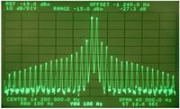
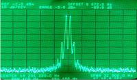
    The Jackson power stage is a linear amplifier and the use of a switching mosfet (and this is the IRF) is an average idea at 28MHz. Yes, the transceiver will deliver power, but the signal will be of terrible quality. This applies not only to harmonics (these are screened on the low-pass filter), but also to signals close to the transmitted signal. To show what the effects may be, I will provide a comparison of the two measurement results. The first is the power level where there is an obvious design error or there are problems with the BIAS:
    Final stage resuscitation CB PRESIDENT JACKSON IRF520N FQP13N10

    And this is what it should look like (Yaesu FT1000Mk5):
    Final stage resuscitation CB PRESIDENT JACKSON IRF520N FQP13N10

    Let me mention that originally President Jackson does not belong to a device with a "clean" transmitter (hardly any CB is "clean"). So if you replace the transistor with an IRF, which you drive badly (and you matched the circuits correctly?), You will get the same effects as in the first photo and it will de facto break the transmitter.
    There is one more important problem there. The circuit on the previous page actually has a wrong gate polarity that will cause nasty interference. I have to search, only found good elaboration on improving efficiency, the problem of IMD is also described there. Here is another study very good in my opinion.

    This Jackson MUST be measured on the analyzer. Because you probably made a noise generator.
    So what is such an IRF suitable for? For power amplifier class C or D (telegraphy, FM, RTTY). That's where it works great.
  • #39 14501006
    Anonymous
    Anonymous  
  • #40 14747480
    Elektronik223
    Level 19  
    The problem with the schema deficiency is that the MOS-FET
    it works linearly in a narrow range of gate polarization.
    * 4.674 gate polarization [V] +/- 1.2%
    * stabilized voltage 5.1 - 5.6 [V] and to the voltage divider
    the above key conditions were not met in the system.
    The point linearity is floating.

    MOS-FET transistors, unlike Bipolar ones, work with voltage.
    voltage should not exceed in total Ugs 10 (15 *) [V]
  • #41 14749850
    Elektronik223
    Level 19  
    By the way, instead of the IRF520 / IRF520N.
    I suggest FQP13N06L.
  • #42 14752175
    Anonymous
    Level 1  
  • ADVERTISEMENT
  • #43 14754326
    Elektronik223
    Level 19  
    IRF510 = FQP13N06
  • #45 14754458
    Elektronik223
    Level 19  
    On the occasion of the experiment, you can swap FQP13N10 and IRF520N, the IRF520N should be given more power. The FQP10N10 in place of the current IRF520N will reduce the signal from the control stage less.

    Added after 25 [minutes]:

    Adamcall wrote:
    buddy pawlik722, except that the power consumption jumped up slightly, the radio works one hundred percent correctly.
    As for the question about the difference in the schema, compare yourself with the original schema.


    From Mitsubishi experiments (RD16HHF1)
    http://www.mitsubishielectric.com/semiconduct...rfdiscrete/siliconrfdiscrete_lv4/rd16hhf1.pdf

    Suggested Gate Source voltage (Ugs) max 4.7 [V] at Uds 12 [V]
    What voltage do you have in your solution on the gate?

    With FQP13N06, PA M0RZF constructions (see IRF510)
  • #46 14754554
    Anonymous
    Level 1  
  • #47 14755845
    Elektronik223
    Level 19  
    Few of the above-mentioned designs are better than the IRF510, you may be tempted to say that they are worse.

    As replacements? you can experiment to re-establish the dynamic parameters of the systems. Well, you have to recount the RLC circuits. taking into account the dynamic parameters of the substitutes.

    SiHF510, (IRF510) vishay

    available here:
    https://www.elfaelektronika.pl/elfa3~pl_pl/elfa/init.do?item=71-148-04&hst=1

Topic summary

The discussion revolves around the modification of the final stage of a CB radio, specifically the President Jackson model, using alternative MOSFET transistors due to the high cost and availability issues of original components. The author successfully replaced the original transistors with IRF520N and FQP13N10, sharing the schematic and components used. Participants in the forum discuss the performance of these substitutes compared to original transistors like 2SC2166 and MRF477, with some expressing concerns about the quality and reliability of replacement parts. The conversation also touches on the importance of proper circuit design, voltage stabilization, and the potential drawbacks of using MOSFETs in linear applications. Various suggestions for alternative components and modifications are provided, highlighting the challenges and considerations in DIY radio repairs.
Summary generated by the language model.
ADVERTISEMENT