logo elektroda
logo elektroda
X
logo elektroda

Final stage resuscitation CB PRESIDENT JACKSON IRF520N FQP13N10

Adamcall 33096 46
ADVERTISEMENT
Treść została przetłumaczona polish » english Zobacz oryginalną wersję tematu
  • Final stage resuscitation CB PRESIDENT JACKSON IRF520N FQP13N10

    I was forced to do this by the price of the original transistors and the ubiquitous coloring.
    So, after analyzing a multitude of diagrams, I came to the conclusion why not to use easily available and commonly used mosfets in new radios.
    I went to work and it worked, so I wanted to share it with you.
    I apologize in advance for the quality of the photos as I was taking a webcam.
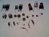
    I started with dismantling the old elements.

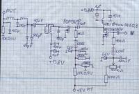
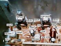
    Final stage resuscitation CB PRESIDENT JACKSON IRF520N FQP13N10

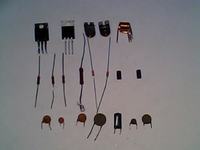
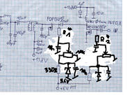
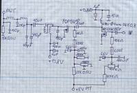
    Next, the diagram of the new stage was created and the necessary components were assembled.
    Transistors.
    IRF520N better IRF510 but I didn't. The price is around PLN 2.

    Final stage resuscitation CB PRESIDENT JACKSON IRF520N FQP13N10

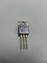
    FQP13N10 price around PLN 5.

    Final stage resuscitation CB PRESIDENT JACKSON IRF520N FQP13N10

    LEDs.
    Zener 5.6V two pieces. Price 2 PLN.
    Resistors.
    1k-10k-100k-47k-47k0.5w. I had.
    Peerki.
    100k two pieces. Price: PLN 3.5.
    Capacitors.
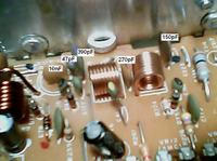
    390pF two pieces. Jackson disassembly.
    47pF. Jackson disassembly
    150pF. I had.
    1.5nF. I had.
    10nF. I had.
    100nF. I had.
    Two ferrite beads. Jackson disassembly.
    Coil twice 3.5 ZW on fi 7mm DNE 1mm. I did.
    The price for the elements is negligible in my opinion.
    Assembly time approx. 3 hours.

    Final stage resuscitation CB PRESIDENT JACKSON IRF520N FQP13N10 Final stage resuscitation CB PRESIDENT JACKSON IRF520N FQP13N10

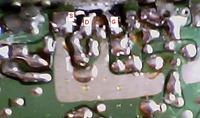
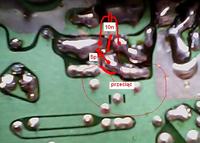
    Then I started editing.

    Final stage resuscitation CB PRESIDENT JACKSON IRF520N FQP13N10 Final stage resuscitation CB PRESIDENT JACKSON IRF520N FQP13N10 Final stage resuscitation CB PRESIDENT JACKSON IRF520N FQP13N10 Final stage resuscitation CB PRESIDENT JACKSON IRF520N FQP13N10

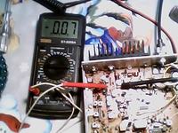
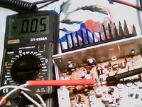
    After assembly, it was the turn of the quiescent currents: driver 70mA, tip 50mA.

    Final stage resuscitation CB PRESIDENT JACKSON IRF520N FQP13N10 Final stage resuscitation CB PRESIDENT JACKSON IRF520N FQP13N10

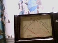
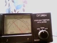
    And now test the power AM 14W SSB 30W.

    Final stage resuscitation CB PRESIDENT JACKSON IRF520N FQP13N10 Final stage resuscitation CB PRESIDENT JACKSON IRF520N FQP13N10

    And this is a link to Transistors.

    http://www.conrad.pl/Tranzystor-MOSFET-Fairch...uctor-FQP13N10.htm?websale8=conrad&pi=1264181

    Maybe someone will need it. Regards Adamcall.

    Cool? Ranking DIY
    About Author
    Adamcall
    Level 17  
    Offline 
    Adamcall wrote 156 posts with rating 75, helped 21 times. Live in city Radomyśl Wielki. Been with us since 2006 year.
  • ADVERTISEMENT
  • #2 14419988
    rekinisko
    Level 22  
    Great article :) It will definitely be useful. Neighbors do not complain after the modifications?
  • #3 14420004
    Adamcall
    Level 17  
    After testing, they perform no worse than 2SC2166 and MRF477.
  • ADVERTISEMENT
  • #4 14420042
    pawlik722
    Level 27  
    Great respect for stuffing it into the original PCB without any additional one. The very new scheme was different from the old one?
    Tell me, buddy, how did the work of this radio improve or worsen? the range has increased maybe?
    I have a dozen or so CBs with such a high-end defect. The main problem I don't fix them is:
    And I got it, I bought it for pennies, I got it in the car
    Original parts cost too much to repair a radio that is not essential to my life
    C the substitutes available in stores are trash 1 in 10 as it works, so I gave up searching.
    Your idea inspired me to work :)
  • ADVERTISEMENT
  • #5 14420211
    Adamcall
    Level 17  
    buddy pawlik722, except that the power consumption jumped up slightly, the radio works one hundred percent correctly.
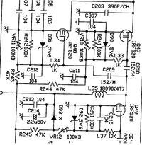
    As for the question about the difference in the schema, compare yourself with the original schema.
  • #7 14420361
    Adamcall
    Level 17  
    Maxxim.
    If you have access to a reliable source, post a link.
    With the area of Adamcall.
  • #8 14420641
    rotkiw19
    Level 10  
    Adamcall

    2SC1945 You can get it from Chinese for about $ 9 ;)
  • ADVERTISEMENT
  • #9 14420841
    zgierzman
    Level 31  
    rotkiw19 wrote:
    2SC1945 You can get it from Chinese for about $ 9 ;)

    Which you can wear ... in shoes, but not in the system being repaired. Because they don't keep parameters and they burn or don't work properly. Fakes and coloring books.
    https://www.youtube.com/watch?v=Q5ahHJjA3ZI
  • #10 14421332
    rekinisko
    Level 22  
    The original 2SC1945 was from Mitsubishi and all the others, unfortunately, are paint jobs that, even if they "work", are a different transistor.
  • #11 14421734
    zdanek15
    Level 26  
    For 10 years I worked in the CB radio service and I will say that sometimes we dismantled the amplifiers to put the client on the MRF, and the 2SC1945 is actually a lame. It's better to use Russian pastilles. However, the idea was brilliant. I need to check. Respect.
  • #12 14422749
    Anonymous
    Level 1  
  • #13 14422769
    Kwazor
    Level 32  
    You certainly do not have 100% modulation in AM, because the modulator will not do that ... So slide down with power, because you are not domodulated on the bank.
    The PA current is 100mA in the original, it was for a single end. So you have too little too.
  • #14 14422810
    Anonymous
    Level 1  
  • #15 14422997
    SQLmaster
    Level 24  
    KrzysztofS wrote:
    I am already writing what it is about, this piece with a Zener diode. Actually what is it about ??

    I was also wondering what their function is and I am not able to comprehend it for anything ...

    Was the output signal observed with an oscilloscope or (which would be great but who has one at home) with a spectrum analyzer?
  • #16 14423186
    maxxim
    Level 15  
    The guy in the movie describes in the description how to buy transistors (he sells them himself). I always use its elements - always good quality, paired, price acceptable.
    Moderated By ANUBIS:

    Link removed.
    3.1.18. It is forbidden to publish information to sources that expire after some time (publishing short-term links to pages).


    zdanek15 wrote:
    For 10 years I worked in the CBradio service and I will say that sometimes we dismantled the amplifiers so that the client could wear mrf and the 2sc1945 is really a lime tree. It's better to use Russian pills. But the idea is brilliant. I need to check.

    When you buy crap from strange cheap stores, you have junk, not transistors.
    I put a lot of "linkolns" on my feet with its transistors.
  • #17 14423285
    Anonymous
    Level 1  
  • #18 14423327
    rekinisko
    Level 22  
    maxxim wrote:
    ... When you buy crap from strange cheap stores, you have junk, not transistors ...

    With all due respect to Cebie, but if you're talking about these transistors from the ebay photo, they're not the originals. There is no need for unnecessary comments, they stopped producing these transistors more than 15 years ago. You can find information about it on the Internet. You just buy another transistor with the inscription reprinted and that they work, congratulations. Only the "same" ones are probably much cheaper before they changed their name.

    ---
    After a few moments of searching, we found a revision of your transistor from ebay. The phrase E3T1 was used by vishay to produce sud40n10-25 mosfets :)
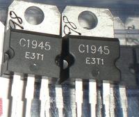
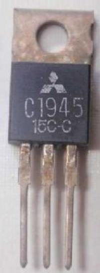
    Final stage resuscitation CB PRESIDENT JACKSON IRF520N FQP13N10

    Final stage resuscitation CB PRESIDENT JACKSON IRF520N FQP13N10
  • #19 14423481
    Adamcall
    Level 17  
    KrzysztofS wrote:
    My friend, however, the price of these transistors is knocking down. It knocks because they are used in Linkolanch and other radios and only because. The strike price is not much different than an IRF. But selling aaa because it is Linkol's. That's why we're saying no here. Better to convert to PLN 5, not PLN 80 :P

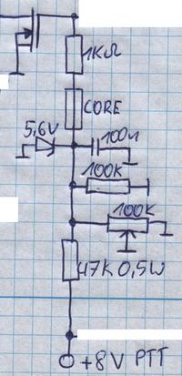
    I would make this polarization like this:


    Final stage resuscitation CB PRESIDENT JACKSON IRF520N FQP13N10


    Of which R1 and R2 should be selected with regard to the load of the HF stage and it should rather be done in a working system. In addition to these zener diodes, I do not understand these resistors in the gates of these selected (core), what for ?? Where is this direct current supposed to flow there ?? My guess is that they were supposed to limit the regulation of these PRs ...
    Regards Krzysztof 73

    As for your correction, first see the original diagram and then incorrectly correct it.

    These diodes do not act as stabilizers in this system.
    http://www.cbtricks.com/radios/galaxy/dx98vhp/index.htm

    Added after 24 [minutes]:

    Kwazor wrote:
    You definitely do not have 100% modulation in AM, because the modulator will not do that much .. so slide down with power because you are not domodulated on the bank.
    The PA current is 100mA in the original, it was for a single end. So you have too little too.

    Since they started to use the AM modulator of the final stage in JACSON, the AM signal is modulated much earlier and the power stage is just an ordinary PA which only amplifies it like a boost.
    As for electricity, everything is here, please.
    http://www.cbtricks.com/radios/galaxy/dx98vhp/index.htm
  • #20 14423561
    SQLmaster
    Level 24  
    Adamcall wrote:
    As for your correction, first see the original diagram and then incorrectly correct it.

    These diodes do not act as stabilizers in this system.
    http://www.cbtricks.com/radios/galaxy/dx98vhp/index.htm

    In your schematic, they don't act as stabilizers. Well, they don't work at all.

    However, in the original, their role is completely different and very ingenious - the polarization of the gates of the MOSFET transistors only when transmitting and turning them off when receiving, so that they do not noise towards the antenna and do not consume power unnecessarily. And yes, they make zenerkas there for stabilizers and for HF voltage rectifiers. They are also connected there completely differently than yours. What KrzysztofS advises is better in your case. If the 8V voltage is already stabilized, these zenerki can be simply removed.
  • #21 14424020
    Adamcall
    Level 17  
    SQLmaster wrote:
    Adamcall wrote:
    As for your correction, first see the original diagram and then incorrectly correct it.

    These diodes do not act as stabilizers in this system.
    http://www.cbtricks.com/radios/galaxy/dx98vhp/index.htm

    In your schematic, they don't act as stabilizers. Well, they don't work at all.

    However, in the original, their role is completely different and very ingenious - the polarization of the gates of the MOSFET transistors only when transmitting and turning them off when receiving, so that they do not noise towards the antenna and do not consume power unnecessarily. And yes, they make zenerkas there for stabilizers and for HF voltage rectifiers. They are also connected there completely differently than yours. What KrzysztofS advises is better in your case. If the 8V voltage is already stabilized, these zenerki can be simply removed.

    What difference do you see. Final stage resuscitation CB PRESIDENT JACKSON IRF520N FQP13N10 Final stage resuscitation CB PRESIDENT JACKSON IRF520N FQP13N10
  • #22 14424283
    SQLmaster
    Level 24  
    Adamcall wrote:
    SQLmaster wrote:
    Adamcall wrote:
    As for your correction, first see the original diagram and then incorrectly correct it.

    These diodes do not act as stabilizers in this system.
    http://www.cbtricks.com/radios/galaxy/dx98vhp/index.htm

    In your schematic, they don't act as stabilizers. Well, they don't work at all.

    However, in the original, their role is completely different and very ingenious - the polarization of the gates of the MOSFET transistors only when transmitting and turning them off when receiving, so that they do not noise towards the antenna and do not consume power unnecessarily. And yes, they make zenerkas there for stabilizers and for HF voltage rectifiers. They are also connected there completely differently than yours. What KrzysztofS advises is better in your case. If the 8V voltage is already stabilized, these zenerki can be simply removed.

    What difference do you see. Final stage resuscitation CB PRESIDENT JACKSON IRF520N FQP13N10 Final stage resuscitation CB PRESIDENT JACKSON IRF520N FQP13N10


    1. This link you provided earlier leads to 20 diagrams, I referred to another.

    2. The difference I can see is that this diode will be idle when powered from 8V:
    Final stage resuscitation CB PRESIDENT JACKSON IRF520N FQP13N10
    You have 8V. Even if you set the potentiometer to the maximum resistance of 100k, the divider will produce a voltage of 4V on the zener diode. EVEN the fact that NIBY this diode would limit the current of the transistor to a reasonable value with the potentiometer being completely broken by the 'radio poker' is not an option. After it is completely broken off, the voltage will be 5.3V. Still not enough to turn on this diode.

    We don't know if the same voltage is there in the original you copied and that may be the difference . Because maybe there is, for example, voltage not 8 but 12V. I don't want to analyze it.

    But if you have an idea why this LED is there, I'll be happy to hear it.
  • #24 14424490
    SQLmaster
    Level 24  
    As for me, you can screw up even 5000 zener diodes there, nothing to do with it.
    But the fact that it is pointless there must be pointed out and I did it - that's why you put this construction on the Eletrody forum to make it (difficult word): assessed!

    If you think that this zenerka is needed there, constructively indicate what for and do not use any strange dodges. If you cannot explain it, you are afraid that you do not fully understand the actions of all the rest: something you copied from there, you put some coils on a stick (unless you calculated and measured them, then I'm sorry) but how does it work? Maybe you would grab your head if you saw the specter? Have you seen

    If you have not seen the spectrum of this self-made, you have not even measured it with an oscilloscope, we can judge the design only by its appearance. You've ingeniously stuffed it into the original PCB. I can rate this much as a plus. Let the hand-made do not disturb the reception of neighbors, spreading harmonics, because then it is not only your business.
  • #25 14424520
    Anonymous
    Level 1  
  • #26 14425083
    maxxim
    Level 15  
    rekinisko wrote:
    maxxim wrote:
    ... When you buy crap from strange cheap stores, you have junk, not transistors ...

    With all due respect to Cebie, but if you're talking about these transistors from the ebay photo, they're not the originals. There is no need for unnecessary comments, they stopped producing these transistors more than 15 years ago. You can find information about it on the Internet. You just buy another transistor with the inscription reprinted and that they work, congratulations. Only the "same" ones are probably much cheaper before they changed their name.

    ---
    After a few moments of searching, we found a revision of your transistor from ebay. The phrase E3T1 was used by vishay to produce sud40n10-25 mosfets :)

    Final stage resuscitation CB PRESIDENT JACKSON IRF520N FQP13N10

    Final stage resuscitation CB PRESIDENT JACKSON IRF520N FQP13N10


    I'm sorry but I don't know where is the problem ??? I have never said anywhere that they were originals, because they are rather hard to buy and there is no point in overpaying.
    And this is a text taken from the auction that explains everything - also what I meant when I wrote about the crap transistors.

    "
    This is a new matched pair of 2SC1945 Eleflow replacement RF power transistors for CB / HAM radios.

    Commonly used in many old type CB transceivers as a PA final and also in some vintage HF transceivers as PA drivers or finals.

    This transistor uses internal CE diode protection and is designed as a direct replacement for the original Mitsubishi device which was

    discontinued in 2003.

    Note; All pairs are matched for within a hFE of 2, most pairs are exact match - hFE range is from 80 - 110.


    2SC1945 SUBSTITUTE APPLICATIONS:

    The 2SC1945 RF transistor can also be used to replace the obsolete 2SC2509 Toshiba and 2SC3133 Mitsubishi RF transistors commonly used in the PA stages of many older HF transceivers.

    2SC1945 = common emitter, B - E - C

    2SC3133 = common emitter, B - E - C

    2SC2509 = common emitter, B - E - C


    WARNING- 2SC1945 FAKES & REFURBISHED!

    The 2SC1945 transistor was discontinued by Mitsubishi in 2003 and like so many devices of this type is now highly counterfeited, many of these Fakes and also refurbished parts (used pulls) are widely available on the market and can be purchased at cheap prices but many are of poor quality and in most cases do not even work - you have been warned!


    SPECS-

    Make, Eleflow Technologies.

    Part #, 2SC1945

    Condition, Brand new

    Package, T-30 = TO-220, FIN = EMITTER (common emitter)

    Type, NPN - EPITAXIAL PLANAR - SILICON, RoHS compliant = Pb free.

    Vcc, 13.8v

    Ic,> 6a peak

    Gain / Gpe,> 14.5db

    Max pwr 'out, 16 watts typical (13.8V @ 27 Mhz)

    Freq 'range> 30 Mhz HF

    Application, Especially suited for use in class A / B power amplifiers in HF band etc.


    title


    Check my other listings for more RF transistors.


    Thanks for looking. "


    KrzysztofS wrote:
    My friend, however, the price of these transistors is knocking down. It knocks because they are used in Linkolanch and other radios and only because. The strike price is not much different than an IRF. But selling aaa because it is Linkol's. That's why we're saying no here. Better to convert to PLN 5, not PLN 80


    This is the price for paired transistors !! Two pieces!
  • #27 14425373
    Anonymous
    Level 1  
  • #28 14426141
    maxxim
    Level 15  
    KrzysztofS wrote:
    You praise them almost as if you were selling them yourself


    And you are opposed as if you were out of the competition ;)
    Seriously ... I'm just presenting an option. Maybe more expensive, but less labor-consuming (and time costs) and proven and less interfering with the original circuits. I think that instead of arguing whether my proposal is better than yours, maybe it is better to think about how to make an appropriate protection of the "tip", e.g. in FT-817ND so that if the standing wave ratio is too high, the power drops and, for example, the red LED signals danger.
  • #29 14427814
    Anonymous
    Level 1  
  • #30 14428397
    maxxim
    Level 15  
    I'm not sure it's that complicated. A small ferrite, a few turns of the diode and we already have a signal which, from a certain threshold, should limit the control of the "tip". Maybe it would not be that difficult to assemble.
    I use the FT-101Z with the DDS and the FT-817ND (only 5W) to work in the CB band.

    The Ft817ND has this great protection feature, and more than once during my antenna tests it happened that the chip beat me up and saved some money.

Topic summary

The discussion revolves around the modification of the final stage of a CB radio, specifically the President Jackson model, using alternative MOSFET transistors due to the high cost and availability issues of original components. The author successfully replaced the original transistors with IRF520N and FQP13N10, sharing the schematic and components used. Participants in the forum discuss the performance of these substitutes compared to original transistors like 2SC2166 and MRF477, with some expressing concerns about the quality and reliability of replacement parts. The conversation also touches on the importance of proper circuit design, voltage stabilization, and the potential drawbacks of using MOSFETs in linear applications. Various suggestions for alternative components and modifications are provided, highlighting the challenges and considerations in DIY radio repairs.
Summary generated by the language model.
ADVERTISEMENT