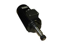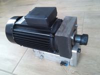
Hello. I would like to present an electro-spindle made by me from a 2.2kW 2800rpm "dachshund" type engine.
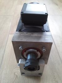
The design was created for use in a small universal milling machine for machining aluminum and steel. I decided on my own design, because within the budget I would have to choose a liquid-cooled Chinese reaching 25 thousand rpm, but not having a sensible torque in the range below 4000 rpm, or Perske or Elte engines available on auction portals, which usually come from carpentry machines, so without modifications, the bearings are unlikely to be suitable for my milling machine, they cannot withstand larger axial loads.
The basis of the project is the STg90-2D engine produced by "Przymierza", with a capacity of 2.2kW at 2800rpm. Lamp holder with socket ER25 I used ready C25-ER25-50.
I was considering making the entire rotor shaft from scratch, however, to avoid a few hours of chip production, I decided to shorten the original 20mm shaft before mounting the front bearing and mount the new hub for the housing and the front bearing on it. Since the diameter of the motor shaft at the seat of the front bearing has the same as the shaft of the housing, the hub has a bore in the center with a diameter of 24.85 mm and is connected to the shaft and housing by thermal shrinkage. The hub bore and bearing mounting surface are machined from one flange, ensuring their concentricity. The hub is made of a steel piston rod with a diameter of 50mm.
When it comes to bearings, I made a compromise using a wheel hub bearing from the Audi A3 (40x74x40). I know I should use a pair of precision angular contact bearings, but the simplicity of assembly and price prevailed. Internal treadmills they are mounted on a hub with a sliding fit and tightened with a KM-8 nut. Original rear bearing, single row ball bearing. Virtually all radial and axial forces are absorbed by the front double-row angular contact bearing, the rear only works with a small radial load, guiding the rotor.
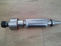
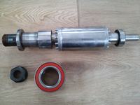
The front engine cover has a bore hole with a diameter of 84 mm in which the new bearing housing, made of steel (piece of forks from the carriage) centers on the lock. The bearing fits inside it with an interference fit of approx. 0.02mm and secured with a Seger ring.
Tool runout measured 20mm from the frame is 0.04mm and I don't know how much of my work in it, and how much of the "rice" frame itself.
The rotor was not balanced, but during operation up to 50 Hz it did not show any major vibrations. I assume work up to 75 Hz (up to approx. 4k rpm), so maybe it won't be a problem.
The entire spindle is attached to the axle with two M10x1.25 bolts from the front and one 10mm dowel from below. The photo shows the hydraulic Z axis from the SMC MXS25-100AS cylinder. From my own experience I know that such cylinders work without any problems with hydraulic fluid up to 3-4MPa. The integrated linear guide is quite stiff and the hydraulics ensure backlash-free operation. But this is already a piece of a separate topic about the milling machine ...


