logo elektroda
logo elektroda
X
logo elektroda

Ultrasonic PWM with soft start for speed control of a DC motor.

heniek07 2469 52
ADVERTISEMENT
Treść została przetłumaczona polish » english Zobacz oryginalną wersję tematu
📢 Listen (AI):
  • Ultrasonic PWM with soft start for speed control of a DC motor.
    Close-up of two prototype boards with electronic circuits, wires, and potentiometers for PWM and soft start control of a DC motor. .
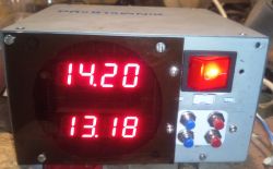
    The circuit was created out of the need to smoothly regulate the speed of a VAG automotive wiper motor. The motor drives the knot toaster shaft via a 2:1 gear ratio. Previous methods using two motor speeds and two voltages from an ATX power supply (somewhat regulated) proved ineffective. The ATX power supply now has the voltage raised to 13.5V permanently. The motor is also reworked - isolated the brush from the ground and an extra wire brought out. This gave the possibility of rotation in both directions.
    In the design I was keen for the system to operate beyond the limit of human hearing, so that no squeaks or whistles could be heard, as it takes about two hours to bake a knot. The regulator I made earlier for drilling into PCBs with a motor from a screwdriver on an LM358 works fine, but you can hear the sound. Fortunately, this PCB activity does not last long. The soft start is designed to eliminate jerks and to cause a slow increase in the current drawn from the power supply, as the ATX power supply's short-circuit protection circuit does not like abrupt changes.
    The project came about after unsuccessful attempts to generate higher frequencies on operational amplifiers and use them as comparators. Searching the web I finally found a triangle generator solution to adopt. The generator worked immediately. I then struggled a bit with MAA741 and LM358 as comparator - they didn't work. A typical HA17393 comparator worked.
    I designed the generator current sources on transistors. I decided that for my application they did not need to be very accurate and replaced the operational amplifiers in the triangle generator (link one) with transistors (any low power pair). I replaced the Zener diode with six ordinary ones because I didn't have one. The generator started and stayed that way. In general, the regulator is made from 'recycled materials', from disassembly and everything that was already there. I only bought a 10k rotary potentiometer and two precision ones of 20k each.
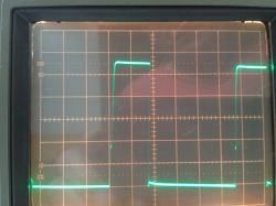
    The regulator from the schematic works at about 16000 Hz. There is no noise or squeaks. A bit about the settings. PR2 is the PWM control. Using potentiometers PR3 and PR4, you can set from which speed the motor should start. The minimum I have set myself is that the motor has a low speed and is always rotating. From this speed, you can adjust up to 100 %. To set the soft-start time, potentiometer PR1 and capacitor C4 are used. (Instead of PR1 there is a 47k resistor.) For starting it is good to have an oscilloscope, but it can also succeed without one. Approximate voltages to set are given.
    I am an amateur electronics technician and the text below is based on internet news.
    The charging (discharging) current of capacitor C01 flowing through resistor R01 (R04) must be small to get a good signal shape, the current flowing through resistor R01 should not exceed 20 mA.
    This current is calculated from the formula
    I=(UD5-D10 - UBE)/R01, I=(3.6V-0.6V)/3800Ω=0.00078947A
    where UD5-D10 is the voltage drop across the diodes - 3.6V(in this case 3*0.6V), and UBE is the conduction voltage at the base-emitter junction of transistor T01 (0.6V).
    If the charging and discharging currents are equal then the charging and discharging times (rise and fall) can be calculated from the formula:
    T=VCC*C01/3*I
    The period will therefore be 2T and the frequency f=1/2T
    View of two electronic circuit boards: triangle wave generator on LM555 timer (left) and PWM controller with soft start on LM393 comparator (right), connected with wires. .
    I am from the generation that was taught the "only right language", so don't be surprised by the Cyrillic alphabet. I used:
    https://www.radiolocman.com/shem/schematics.html?di=655279
    https://www.rlocman.ru/shem/schematics.html?di=655279
    http://zpostbox.ru/sawtooth_wave_generator_based_on_555_timer.html
    https://www.elektroda.pl/rtvforum/topic1047137.html#5295680
    The layout meets my expectations. I am posting with the hope that someone will use it. I'm not posting the circuit boards because it's a bit of a hybrid made up of two boards. The first is a triangle waveform generator on an LM555 timer. It's good, no tweaks, but it's just a 555 cube and literally a few components. The second is a soft-start PWM, now on an LM393 comparator. Previously there were trials on an MAA741 operational amplifier and an LM358. There is now an adapter in a half spider from the 741 to the 393, a few jumpers and components on either side of the board, so it doesn't make much sense. I chose to split it into 2 boards because of:
    - lack of space in the chassis where the circuit has to fit,
    - I didn't know if the circuit would work (I'm just an amateur and I have big deficiencies in electronic knowledge, I decided to divide the project into a generator and a PWM regulator, hoping that if the generator works, then I will deal with the PWM with soft start, on this or another schematic).
    Unfortunately the last point worked out fine, I was combining on a couple of versions.
    Close-up of two prototype electronic modules: one with LM555 chip, the other with LM393, on breadboards with visible wires and electronic components. .
    Just before maximum filling.
    Two photos of a PWM electronic circuit: one showing maximum motor speed setting, the other the minimum speed setting. .
    Set minimum turnover.
    09. 07. 2025 r.
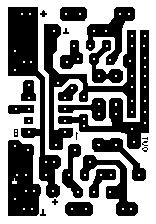
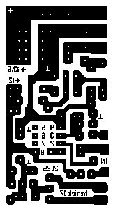
    I am posting the reworked tiles, in the hope that perhaps a colleague will benefit. It is still a hybrid solution. If anyone needs to convert, please write to PW. The tiles are done in plain Paint. A long time ago I made a small project on the fly and it stayed that way. Then it was just copy paste. I know there are dedicated programs, but my penultimate board was made in 2022.
    Tiles:
    Ultrasonic PWM with soft start for speed control of a DC motor. Ultrasonic PWM with soft start for speed control of a DC motor. .

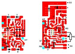
    Elements on pathways:

    Ultrasonic PWM with soft start for speed control of a DC motor. .
    10. 07. 2025 r.
    Boards together, you will not need one jumper - Z3 on the triangle generator. You need to connect OUT to IN.
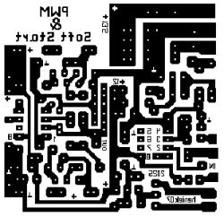
    Ultrasonic PWM with soft start for speed control of a DC motor. .

    Cool? Ranking DIY
    About Author
    heniek07
    Level 20  
    Offline 
    heniek07 wrote 423 posts with rating 205, helped 27 times. Live in city Nowogród. Been with us since 2006 year.
  • ADVERTISEMENT
  • #2 21599063
    ArturAVS
    Moderator
    You have not taken into account that too high a frequency, will generate losses in the (steel) cores. The maximum that is used is 200 - 500 Hz. 16 kHz is the frequency of the FBT in CRT TV.
  • #3 21599067
    heniek07
    Level 20  
    The lack of squeak in the ears is more valuable in this application than the loss of energy.
  • #4 21599076
    żarówka rtęciowa
    Level 38  
    Hello

    I think it would be simpler to make a regulator using a typical PWM modulator e.g.: UC3843, or TL494.

    https://320volt.com/en/motorlu-bisiklet-icin-motor-surucu-devresi-tl494-pwm

    In this case you could even stabilise the speed.

    ArturAVS wrote:
    You have not taken into account that too high a frequency, will generate losses in the (steel) cores.
    .

    A suitable low-pass filter connected to the motor consisting of a choke and a low impedance capacitor can be used. Here is an example of such a solution:

    https://ludens.cl/Electron/latsup/latsup.html

    Of course, the circuit could be converted to a low supply voltage as in the author's case.
  • ADVERTISEMENT
  • #5 21599110
    heniek07
    Level 20  
    Amateur to professional question:
    If I use a pulse capacitor of 0.1 to 1µF in parallel to the D1 diode, could it be that the motor will run at some constant voltage without dropping to zero? I saw such a solution on one of the eastern sites.
    Greetings
    Heniek
  • #6 21599168
    CosteC
    Level 39  
    heniek07 wrote:
    If I use a pulse capacitor of 0.1 to 1µF in parallel to diode D1, could it be that the motor will run at some constant voltage without dropping to zero?
    .
    If you do this you will be putting short circuit pulses through T3 that are limited by this new capacitor. Bad idea. Losses will reach C*U^2*0.5*f.
    A low-pass filter, preferably LC, falls between the drain of T3 and pin 5 of the relay. It will reduce the AC component of the motor current, reduce losses but also make it difficult to change the direction of rotation very quickly.
  • #7 21599239
    heniek07
    Level 20  
    Thank you. In that case, I won't be doing anything else.
  • ADVERTISEMENT
  • #8 21599282
    CosteC
    Level 39  
    I admire that you wanted to do PWM on foot. There are so many circuits that integrate this. The UC3843 mentioned allows you to control peak current, for example. And it's very old and readily available.
  • #9 21599290
    heniek07
    Level 20  
    As I wrote. I am an amateur not a professional. My knowledge is fragmented. I don't know which components are dedicated to certain applications. What was needed was a PWM with soft start. I use the first such circuit on an LM358 to drill into boards using a motor from a screwdriver. I was unable to tune it and the wiper motor gave out a squeal. The schematic from the last link. I searched on the internet and after a number of attempts it worked.
  • #10 21599295
    fred_onizuka
    Level 19  
    heniek07 wrote:
    The lack of squeak in your ears is more valuable in this application than the loss of energy.

    I'm afraid the squeal is there and reaching your ears, only you can't hear it. I probably wouldn't hear it either. But 16 kHz is within the range heard by humans (it's not ultrasound) and very young people (teenagers) should be able to hear it (it might bother them).
  • #11 21599303
    heniek07
    Level 20  
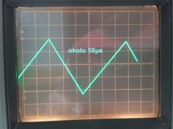
    The 58µs period is about 17 241Hz.
    I'll have to bring in someone younger and ask for detection. If it bothers the youngsters I will reduce the capacitance of C01 from 5.5nF - it is put together with 3.3nF and 2.2nF. Maybe 3.3nF + 1nF will be enough to get the frequency up to 22kHz.
  • #12 21599352
    Rocky Horror
    Level 31  
    heniek07 wrote:
    The first is a triangle waveform generator on a timer LM555 . (...) The second is a PWM with soft-start capability, now on a comparator LM393 .
    .
    I would be afraid to meet you on the road in a snowstorm in a crackling cold :-) . The most relevant components used are of consumer standard - i.e. designed for temperatures of 0-70°C, reliable operation below and above this range is not guaranteed. You should use at least a SA555 generator, which operates from -40°C, and a LM293 comparator, operating from -25°.
    Most designers forget that the automotive industry has somewhat stricter requirements for component reliability. It's not bad if it's a converter and an amplifier for the speakers, but windscreen wipers are a rather important function in terms of road safety and it's worth considering the worst possible eventualities here.

    heniek07 wrote:
    No squeak in the ears is more valuable in this application than energy loss.
    But I'm afraid it's not as valuable as adequate motor torque. The windscreen wiper mechanism can stagnate from prolonged disuse, or sticking/freezing feathers to the glass and the engine must have the power to jerk them out. A soft start, which further limits this initial momentum, can unexpectedly be a very damaging function, causing the mechanism not to start at all if the wiper speed is not set high enough.
  • #13 21599378
    fred_onizuka
    Level 19  
    >>21599352 .
    I understood from the author's description that, although the motor came from a car windscreen wiper, it was used for a completely different purpose: "The motor drives the shaft of the knot toaster". And there negative temperatures are unlikely to occur.
  • #14 21599453
    acctr
    Level 38  
    heniek07 wrote:
    If I use a pulse capacitor of 0.1 to 1µF in parallel to diode D1, could it be that the motor will run at some constant voltage without dropping to zero?
    .
    Such capacitors quite possibly are already inside this motor, paired with chokes. They form a low-pass filter.
    However, it is better to control the dips to zero on the comparator side.
    CosteC wrote:
    Losses will reach C*U^2*0.5*f.
    .
    Since when do losses occur on capacitance?
    Helpful post? Buy me a coffee.
  • #15 21599634
    Rocky Horror
    Level 31  
    fred_onizuka wrote:
    I understood from the author's description that, although the motor came from a car windscreen wiper, it was used for a completely different purpose: "The motor drives the shaft of the knot toaster".
    Ha! Well, yes. mentioned briefly at the very beginning of the description, somehow it got lost in the whole size of the text. Well, there was no issue :-) .
  • #16 21599641
    ArturAVS
    Moderator
    heniek07 wrote:
    The motor drives the knot toaster shaft
    .
    I built something like this last year. Attiny85 + a couple of discrete components and two relays. Soft start (in both directions, change of direction automatically with deceleration) nothing squeaks despite low PWM frequency.
  • #17 21599855
    heniek07
    Level 20  
    Mate ArthurAVS can you reveal, to a colleague from the same province (almost a countryman), the frequency at which your PWM operates. To me, just change the capacitance of C01 to a larger one and the PWM frequency will decrease. My toaster is not a production machine, it's a basement appliance for home occasional knot baking and I didn't combine with excessive automation.
  • ADVERTISEMENT
  • #18 21599969
    ArturAVS
    Moderator
    @heniek07 I can't remember exactly anymore, but about 10kHz on a hardware PWM. Programmatically you can probably get more like 25kHz out.
    Switch, button, 10k potentiometer and two relays (I didn't have one with two pairs of contacts).
    Switch on, after about 3 seconds it accelerates to the speed set with the potentiometer.
    When the direction change button is pressed, it smoothly reduces the speed to zero, switches direction and accelerates again to the set speed.
  • #19 21600177
    heniek07
    Level 20  
    >>21599969 .
    Thank you!
  • #20 21601294
    reaven22
    Level 31  
    It uses adjustable step-down converters to regulate the speed of the DC motors, reducing the voltage. We have a full range from zero with no squeaks.
    Inverters for a couple/teen PLN each with a soldered PR external instead of a precision one.
  • #21 21601395
    CosteC
    Level 39  
    Folks... @heniek07 did the circuit his way, it's not perfect, but it works. The amount of knowledge required to do it on foot is impressive, and a lot of electro-geeks wouldn't be able to do it. Especially using an analogue oscilloscope. A very good educational project.

    The festival of clinginess from the little people who didn't even read the original post is quite disgusting.

    Anyone can buy a Chinese module and plug it in, but it's hard to learn anything using off-the-shelf modules. Well, unless you are a professional, in which case you can learn why not to buy cheap Chinese modules.
  • #22 21601966
    heniek07
    Level 20  
    Thank you fellow CosteC for your words of encouragement. I'll write again. I am an amateur, perhaps a hobbyist but not a professional electronics engineer. The project was based on my modest expertise and on what I found on the forum, i.e. the regulator from this link.
    https://www.elektroda.pl/rtvforum/topic1047137.html#5295680
    That solution would have satisfied me. The ATX power supply would not be loaded by sudden current spikes, which it does not like. Unfortunately on the original frequency the motor gave out a squeal and it was not possible to tune the circuit there to a frequency towards the ultrasonic. So I went on a search in that direction. I found a schematic of a triangle generator, then added a comparator with a soft start and after a few failed attempts it worked. For my application this is sufficient. It works and fulfils its purpose. If I hadn't succeeded, I would probably have kept looking. Maybe I would have come across microcontrollers and programmed them after a while. I have been coping with computers for 30 years and Fortran, Basic, Visual Basic, Pascal, C++, Python tells me something. I can also handle a six nested If statement in Excel. Also, who knows, maybe the next project will be based on Arduino.
    It's been raining since this morning, so I've reworked the pcb boards, in the hope that one day I'll replace the makeshift, or I'll need to make another circuit like this. I converted the boards from double-sided to single-sided, because aligning the two planes in amateur conditions is difficult. One time it is perfect and the next time it is offset by 1 mm. Originally I only had a double-sided laminate and this was the design. I am posting the boards in the first post in the hope that someone might use them.
    Regards
    Heniek
  • #23 21602020
    efi222
    Level 20  
    reaven22 wrote:
    It uses regulated step-down converters to regulate the speed of DC motors, reducing the voltage
    .
    With such regulation, torque drops dramatically.
  • #24 21602028
    ArturAVS
    Moderator
    heniek07 wrote:
    the next project will be based on Arduino
    .
    Arduino is practically C++...
    heniek07 wrote:
    I converted the boards from double-sided to single-sided because aligning the two planes in amateur conditions is difficult. One time it is perfect and the next time it is offset by 1 mm. Originally I only had a double-sided laminate and that was the design.


    https://www.elektroda.pl/rtvforum/topic3937477.html#20307300
  • #25 21602174
    heniek07
    Level 20  
    Mate ArturAVS - you have a beautifully equipped workshop. I am an amateur making tiles by heat transfer on I think siliconised paper. I applied centering crosses to the edges of the plates, assembled glued them together. Then I put between two plates of silicone rubber 2 thick and into an old vulcaniser made in USSR with a thermostat. When pressed down, it can move by almost 1 mm. The disadvantage of this is the small dimensions of the plates, but an amateur is unlikely to make projects similar to yours.
    Regards.
  • #27 21602511
    koczis_ws
    Level 27  
    heniek07 wrote:
    No squeak in the ears is more valuable in this application than energy loss.

    And I went the other way. For the gate drive, I set the PWM frequency to 50 Hz. Now instead of an unpleasant squeak I have a nice purr , like a cat :) .
    At start-up and run-up, of course.
  • #28 21602842
    heniek07
    Level 20  
    When drilling into the tiles, I can withstand the sound, as the activity does not take long. Unfortunately, the knot is produced in 2 - 2.5 hours. That's a long time to listen to unpleasant sounds.

    I have also added to the first post a drawing of the tiles joined together. The total is about 6 cm x 6 cm.
  • #29 21605827
    jarek_lnx
    Level 43  
    heniek07 wrote:
    The project came about after failed attempts to generate higher frequencies on operational amplifiers and use them as comparators.
    I don't understand why people try to use amplifiers as comparators. What's the point in that?

    If I wanted a generator with linear slopes then maybe I would make one like yours, but do you need linear slopes?

    The simplest circuit with a comparator is like this
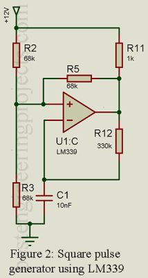
    Diagram of a simple triangular waveform generator using a comparator and a capacitor. .
    The triangular waveform is on a capacitor
    It gives slightly skewed slopes but in this application what does it matter?
  • #30 21605833
    CosteC
    Level 39  
    jarek_lnx wrote:
    I don't understand why people try to use amplifiers as comparators. What's the point in that?
    .
    Because:
    - Same symbol.
    - Same basic operation (very high-gain open-loop differential amplifier).
    - Because they have bunches of operational amplifiers in the drawer.
    - Because they don't always need the OC output, which sometimes hinders rather than helps due to the frequent reference to the negative power rail.
    - Because it would often be better to have a symmetrical output.
    - Because understanding the differences in construction and operation is not that simple and rarely well explained.
📢 Listen (AI):

Topic summary

The discussion centers on designing an ultrasonic PWM speed controller with soft start for a DC motor originally from a VAG automotive wiper, repurposed to drive a knot toaster shaft. The goal was to achieve smooth speed regulation without audible squeaks by operating the PWM frequency above human hearing (around 17-22 kHz). Initial designs using LM358 op-amps as comparators produced audible noise and slow switching edges, prompting suggestions to replace them with faster LM393 comparators and improve the MOSFET gate drive circuitry. The use of a low-pass LC filter was recommended to reduce current ripple and losses, though it may slow direction changes. Soft start implementation was discussed, including adding a PNP transistor with RC and diode for independent timing to prevent power supply trips during direction changes. Component reliability for automotive conditions was noted but deemed less critical for the indoor knot toaster application. Various PWM generation methods were compared, including dedicated ICs like UC3843 and TL494 for more stable speed control. Gate resistor values around 22-100 Ω were debated to balance switching speed and EMI. The final working solution uses a triangle wave generator with a comparator, soft start, and MOSFET switching at about 17 kHz, achieving silent operation and stable motor control. The project is an educational example of analog PWM design by an amateur, with ongoing refinements based on community feedback.
Summary generated by the language model.
ADVERTISEMENT