logo elektroda
logo elektroda
X
logo elektroda

FS-05R Mini Dimmer Firmware Replacement Issue with I/O Configuration

lbelleboni 6696 52
ADVERTISEMENT
  • #1 20901164
    lbelleboni
    Level 3  

    Ciao to everybody!
    I follow your guide in order to replace the original firmware for a smart dimmer (no brand, FS-05R) as you can see in the attached image.
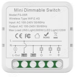
    Mini dimmable switch with a technical label on the front.

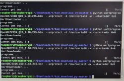
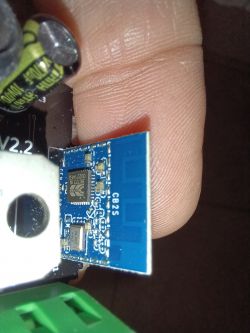
    I was able to do the job only removing the CB2S module from the main board:
    Smart dimmer module FS-05R held in hand

    Everything seems to be fine except that it doesn't work: the "automatic" configuration doesn't give all the I/O configuration (or I'm using it wrong). Is there someone that can help me?
    Attached is the backup of the original firmware.

    I'll send to the forum all the pictures and info in order to add this module to your database later, when I can provide you with all the running project.

    Thank,
    Luca @ElektrodaBot
  • ADVERTISEMENT
  • #2 20901172
    p.kaczmarek2
    Moderator Smart Home
    Hey, isn't it a TuyaMCU device? How does it look like from the other side?

    For TuyaMCU devices, you don't get automatic configuration, you will need to paste autoexec.bat yourself.

    Search for TuyaMCU dimmers here:
    https://openbekeniot.github.io/webapp/devicesList.html
    Here is a sample detailed teardown of dimmer with the configuration steps:
    https://www.elektroda.com/rtvforum/topic3929151.html
    Helpful post? Buy me a coffee.
  • #3 20901283
    lbelleboni
    Level 3  

    I haven't found a similar product in the list; this is why I tried to follow your guide and ask for your help.

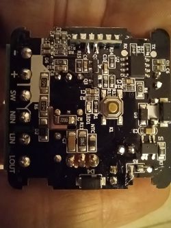
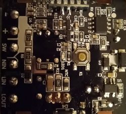
    These are other pictures of the device in question:

    Printed circuit board with various electronic components. Close-up of an electronic module with components on a blue circuit board and nearby capacitors.

    I do not know exactly how it works, but from the automatic configuration file I can see which are the I/O to be used (led, light_minus, light_plus, on/off button) but I have no idea how to set the dimmer setting. I'll read all the info from the link you gave me.

    Feel free to ask me for other more detailed pictures.
    I have another device to be flashed so I can obtain original data if required.

    Thanks,
    Luca
  • #4 20901379
    p.kaczmarek2
    Moderator Smart Home
    It seems that you have a very unique device. I haven't seen that kind of type before. Here is the JSON:
    Code: JSON
    Log in, to see the code

    Still, I can see the baudrate settings there:

    Can you try the following autoexec.bat:
    
    // start TuyaMCU driver
    startDriver TuyaMCU
    // set TuyaMCU baud rate
    tuyaMcu_setBaudRate 115200
    // set TuyaMCU default wifi state 0x04, which means "paired",
    // because some TuyaMCU MCUs will not report all data
    // unless they think they are connected to cloud
    tuyaMcu_defWiFiState 4
    

    save, reboot, and then execute command in the web app log:
    
    tuyaMcu_sendQueryState
    

    Does it cause TuyaMCU to respond with some data?
    Helpful post? Buy me a coffee.
  • #5 20901655
    lbelleboni
    Level 3  

    Ciao.

    I haven't yet read all the information you gave me in the previous link.

    Attached you can find the log from start to the command execution (supposing I did the right operation :-)

    I promise you to study this evening in order to be more reactive and I can be more involved in this project.

    Thanks,
    Luca
  • #6 20901696
    p.kaczmarek2
    Moderator Smart Home
    Unfortunatelly it doesn't looks like TuyaMCU. IT looks like some custom UART protocol. Do you have original firmware backup?
    Helpful post? Buy me a coffee.
  • ADVERTISEMENT
  • #8 20901755
    p.kaczmarek2
    Moderator Smart Home
    Would you be able to restore the original firmware and do an UART capture in safe manner? By a safe manner, I mean, with all the galvanic isolation provided for UART lines, so you don't blow up your PC by shorting mains to the USB port?
    Helpful post? Buy me a coffee.
  • #9 20901782
    lbelleboni
    Level 3  

    I have another FS-0R "original" module, so I should use it... but in order to be able to communicate/program the CB2S module, I have removed the module from the main board because I was not able to communicate at all.

    If your request is to "sniff" the rx/tx while the device is powered... then I have to look at the USB converter, but I'm quite sure that it is not isolated (cheaper Chinese converter).

    https://it.aliexpress.com/item/4000120687489...._main.490.21ef3696YbNOIR&gatewayAdapt=glo2ita

    Maybe I can use a very old laptop PC, but I need to use the AC instead of battery because it's "gone" and the risk of burning everything is big!
  • #10 20901821
    DeDaMrAz
    Level 19  
    @lbelleboni

    You can use ADUM1200 or ADUM1201 modules from Analog Devices, the modules are something like 2-5$ on AliExpress and they provide galvanic isolation for safe data capture and are tested to work several times now.
  • #11 20919033
    adolfonovo
    Level 7  

    I have two of these devices and cannot even flash them. The software cannot detect the bus.
  • #12 20919036
    p.kaczmarek2
    Moderator Smart Home
    This is a common issue in TuyaMCU devices. You need to cut the RX/TX lines from the MCU in order to flash. Alternatively, you need to put the MCU into the RESET mode, if you have a datasheet for that and know how to do it.
    Helpful post? Buy me a coffee.
  • #13 20919198
    adolfonovo
    Level 7  

    Thanks, but you said above that this is not a tuyaMCU device... don't you? How can I enter flash mode? Where is the CEN pin?
  • ADVERTISEMENT
  • #14 20920381
    lbelleboni
    Level 3  

    HI.

    Unfortunately, either you find the TX and RX tracks on the printed circuit and interrupt them, or you do like me who desoldered the CB2S module from the printed circuit and programmed it.

    However, if you read the previous messages, I was unable to find the right configuration to make it work; I'm waiting to receive a serial converter to "sniff" the serial with the original firmware (and I have to hope to restore it because the second module I purchased that I left with the original firmware died for no reason). Maybe you can get the job done and help me set up.

    HI,
    Luca
  • #15 20920659
    adolfonovo
    Level 7  

    >>20919198
    I got it by interchanging rx and tx pins, maybe a silk error.
    Now I can erase all... but when it starts writing, I get:
    writing sector 0x00... writing sector 0 failed!
  • #16 20921075
    lbelleboni
    Level 3  

    As I wrote before, I desoldered the CB2S board in order to be able to program it; otherwise, I still have errors. Probably there is a capacitor somewhere in the same TX/RX line.

    But before doing the job, did you read post #8? If you are able to "sniff" the device before changing the firmware, then I think that our guru p.kaczmarek2 can help us.

    You have to sniff both RX and TX (using just the RX of your COM port) in each condition: startup, power on/off the device with the electrical switch, using the dimmer +/- (electrical switch), and while doing the job with the APP. You have to sniff the RX signal first and then do the same job, sniffing the TC signal.

    @p.kaczmarek2, Correct?
  • #17 20921414
    adolfonovo
    Level 7  

    Yes, I can do it, but do I need some special device?... I just have a USB-TTL. Could you explain to me how to do the sniff?.... and what to do?

    Another question... why am I getting this:

    Failed with serial.BytesToRead 5 (expected 15)
    The beginning of the buffer in UART contains 0000000000 data.
    Writing sector 0x00... Writing sector 0 failed!
    Writing file data to chip failed.


    If desoldering will be mandatory, I wouldn't be able to erase the data also, would I?
  • #18 20922288
    lbelleboni
    Level 3  

    Hi AdolfoNovo,

    I think that we need an isolated serial port because we need to have the dimmer unit connected to 230VAC. I bought a unit in China because I have a non-isolated unit; I'm waiting for it to arrive.

    @p.kaczmarek2: If I understood correctly what you wrote to me, we have to log all the communication running to CB2S during each Wi-Fi command and each on/off dimmer +/- command. Of course, we have to connect just our RX signal, one time to CB2S TX signal and repeat the same with the CB2S RX signal. @p.kaczmarek2, is that correct?
    Are we still sure that there is another "intelligent" device on the board that communicates with CB2S?

    Best Regards,
    Luca
  • #19 20922292
    adolfonovo
    Level 7  

    Ok, I understand. Well, what should be isolated?... the adapter?... the USB? I cannot figure out why we need that because I think that even connected to 230V, the CB2S board is fed with 3.3V. Am I wrong?
  • ADVERTISEMENT
  • #20 20922303
    p.kaczmarek2
    Moderator Smart Home
    If you want to power from mains, the UART of course has to be isolated, there are some chips optoisolators on aliexpress.
    Alternatively, you could try powering your device from USB, of course assuming that your device has 5V on the board (going to the input of LDO, to provide 3.3V for WiFi module) and try to do capture then.


    lbelleboni wrote:

    Are we still sure that there is an other "intelligent" device on the board that communicate with CB2S?

    This is the photo that was posted:
    Close-up of a circuit board with visible integrated circuits, including markings TX, RX, and MCU.
    U1 is a power supply chip, that converts mains to something like 12V or 5V, depending on the device, I don't know.
    U2 looks like the MCU.
    Another strong indication that there is something UART-related going on is the TX and RX pad near U2.
    I think you can check with your multimeter (with the device disconnected from power, of course!) in the continuity test mode that RX1 and TX1 are connected to U2 chip.
    Helpful post? Buy me a coffee.
  • #21 20922317
    adolfonovo
    Level 7  
    Thanks p.kaczmarek2!...

    Let's see if I understood. In your alternative way, we should power on the device, and do we have to do it directly through the LDO? I can take either 5V or 3.3V from the USB-TTL adapter. What should I use?

    Another question. How is the process to sniff? What is the software for that? just using putty for example?

    Added after 10 [hours] 38 [minutes]:

    >>20922303

    I have measured continuity between U2 and TX and RX pad and TX-> pin 8 and RX->pin 1

    Also, Im not be able to program with anything even qith the ol hid aplication
  • #22 20924289
    adolfonovo
    Level 7  

    Finally, I was able to flash the device, only unsoldering the CB2S board, as Luca said.
    I have tried several configurations and none of them work.
    I can't even find the Relay pin.

    I think that IC (U2) has been orphaned by programming OBK separately from the board.
    What do you think?
  • #23 20924355
    p.kaczmarek2
    Moderator Smart Home
    As I said, you will not be able to find a relay pin, because this device works like TuyaMCU, so all control is done via U2 and WiFi module controls U2 via UART (RX1 and TX1). We need to have a capture of UART 1 traffic with original firmware to see how it's done. Then we will need to replicate this communication protocol on OBK.
    Helpful post? Buy me a coffee.
  • #24 20924388
    adolfonovo
    Level 7  

    Thanks a lot for the quick response. Is there any tutorial to follow in order to make such UART sniffing?
  • #25 20925952
    adolfonovo
    Level 7  

    Hello, just a question about this, @p.kaczmarek2.

    LED and button are controlled also by the PCB microcontroller? I can control by panel setting up P7 and P8
    "pins": {
    "7": "Btn;1",
    "8": "Rel_n;1"
    },

    I do not know if this is a normal behavior or is important.
  • #26 20927773
    adolfonovo
    Level 7  

    >>20922303

    In reply to this question RX1 and TX1 of the CB2S are not connected to U2

    Regards
  • #27 20927786
    p.kaczmarek2
    Moderator Smart Home
    I am afraid that we need you to draw a schematic of this device, because I am not able to understand how CB2S connects to U2.

    You said:
    adolfonovo wrote:

    I have measured continuity between U2 and TX and RX pad and TX-> pin 8 and RX->pin 1

    adolfonovo wrote:
    >>20922303
    In reply to this question RX1 and TX1 of the CB2S are not connected to U2

    You can also consider just sending this module to me so I can do measurements on side and provide you with results.
    Helpful post? Buy me a coffee.
  • #28 20927840
    adolfonovo
    Level 7  

    Yes, of course... that's great!!!

    I have a brand new intact. Just linked with the Tuya app..

    Send me a PM with your address and I will send it to you
  • #29 20983210
    lbelleboni
    Level 3  
    Ciao p.kaczmarek2.

    Do you have some news about this device?
    Thanks,
    Luca
  • #30 20983327
    p.kaczmarek2
    Moderator Smart Home
    This device is super confusing.

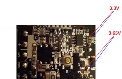
    1. It has no LDO and no extra step down converter, the main step down converters changes mains to 3.6V and then, after one diode, we already have 3.3V for WiFi module:
    Interior of an electronic circuit with voltage labels
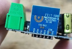
    2. the CB2S has incorrect silkscreen:
    Close-up of an electronic module with a green connector and blue printed circuit board.
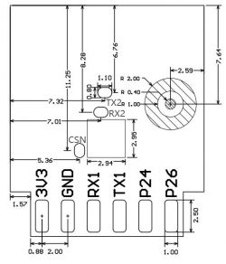
    Correct one is:
    Electrical circuit diagram with pin labels and measurements.

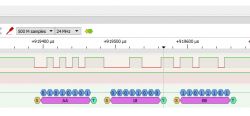
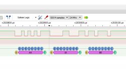
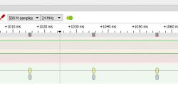
    There is some movement on TX/RX. Doing nothing:
    UART signal measurements in PulseView
    Zoomed in:
    Screenshot of protocol analyzer with UART signals
    Next packet:
    View of captured UART protocol on a logic analyzer
    Next one:
    Screenshot of UART signal analysis using Saleae Logic.

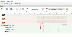
    Single button press:
    Screenshot from PulseView showing UART data.
    Zoomed in:
    Screenshot of UART signal analysis in a logic analyzer.
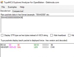
    Hmmm 55 AA ?
    Screenshot from a logic analyzer showing UART data.
    Hm"
    TuyaMCU Explorer application interface displaying raw packet data in hex format.
    Helpful post? Buy me a coffee.

Topic summary

The discussion revolves around issues faced while replacing the firmware of the FS-05R smart dimmer, which lacks a clear brand identification. The user, Luca, successfully removed the CB2S module to attempt the firmware update but encountered problems with I/O configuration and device functionality. Various participants suggested that the device might not be a TuyaMCU and proposed using UART for communication. They discussed the need for galvanic isolation during UART captures to prevent damage to connected devices. Luca shared logs and configurations, seeking assistance in setting up the dimmer to function correctly with external switches and voice commands. The conversation included troubleshooting steps, firmware configurations, and the importance of capturing UART traffic to understand the communication protocol. Ultimately, Luca managed to flash the device but faced issues with random reboots and temperature readings, prompting further investigation into the device's stability and configuration.
Summary generated by the language model.
ADVERTISEMENT