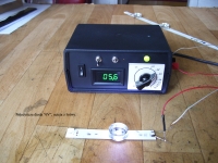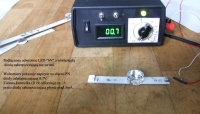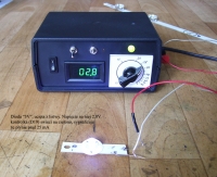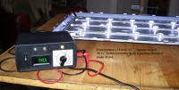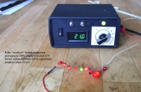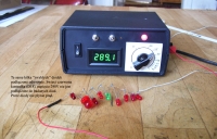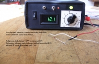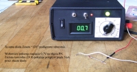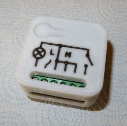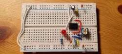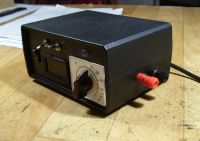
LED and led backlight tester.
Inspired by this topic on the forum of Russian colleagues:
http://monitor.net.ru/forum/topic544255-0.html
I decided to build a similar device. The topic is interesting for all 6 pages, although it still describes one solution in various implementation variants.
My design assumptions were similar, but slightly different. First of all, I decided to make a protection against incorrect, reverse connection of the tested LEDs, which usually results in damage at higher voltages, especially when there are a small number of LEDs in series. Despite paying attention to it, it is only a matter of time before you accidentally connect it backwards.
Of course, the problem does not apply to the LEDs secured with an additional parallel diode, but not all LEDs have it.
It is not always possible to check whether the LEDs are protected by diodes, especially when there is no (easy) access to separate diodes in the tested device. To check several diodes in series, or even some separately, you need a higher voltage, not available with ordinary ohmmeters.
I also gave up the ammeter, because I think that it is not needed in such a tester. The flow of current from the current source during the duration is indicated optically by a large green LED (D19), additionally, when the current is turned on, there is a short sound signal (a useful function when the eyes and hands are busy connecting the measuring tips). To adjust and read the current value, you only need a potentiometer and a large, comfortable knob with an indicator above a readable scale.
The required current value can be set even before connecting the tester to the mains.
The tester has protection against high voltage shock (+ 290V) in case of short-term accidental touching of the test tips.
With the automatics turned on, the constant voltage + 290V or + 8.5V on the measurement terminals (Dx) appears after 1 second from the moment of the cause, i.e. connecting the LED, or the resistance of touching both terminals simultaneously. During this 1 second there is a variable voltage of ~ 200V on the Dx sockets, but it is not dangerous, not perceptible because it is supplied by a very high resistance of the R3 and R3a resistors.
The protection will not prevent electric shock when you touch the tips for "deliberately" long, longer than 1 second. I assume that dilettantes will probably not use such a tester.
With the automatics turned off (switch W2 closed), the protection against electric shock and inverse turning on the LED does not work, the constant voltage + 290V or + 8.5V is "rigidly" connected to the Dx input.
Disabling the automatics is signaled by the red D20 diode.
After switching off the automation and setting the minimum current, you can check any, even the smallest Zener diodes, both at a voltage of + 8.5V and a voltage of + 290V. The zener voltage will show the voltmeter.
If we have a larger number of "unknown" LEDs in our inventory, sacrificing one can check what is the permissible blocking voltage by testing like a zener diode. As a rule, the LED will not be completely damaged, but "bad", it will be possible to check with an ordinary ohmmeter that the resistance in the reverse direction has decreased even to a few kilohms, although it still shines well when properly connected.
General rule after switching off the automatics you need to "know what you are doing" .
Nowhere have I found any sensible system that would allow to detect the connection direction of the tested LED. Finally, I came up with the idea that every LED is a "bad Zener diode", and has some rectifying properties, so after rectifying the AC voltage on the detection bridge, you can get a positive or negative voltage depending on the direction of the diode connection.
Typical characteristics:
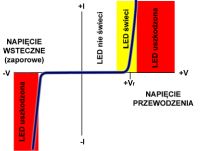
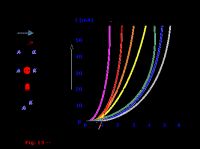
The problem is that the tested "Dx" diode resultant is not specified.
It can be one diode and then an alternating voltage of a few volts is enough. It can be a few or a dozen LEDs, or even about 100, and then the alternating voltage should be at least 200V. Manufacturers usually do not provide permissible reverse voltage in their catalogs (the mentioned "bad Zener diode"), and this voltage, depending on the manufacturer, color, type of diode, may vary from a few volts to about 50V and more. I checked it while examining about 100 different diodes, of which about 30 were specially "destructive tests".
In addition, the alternating voltage should be symmetrical in shape so that you can clearly distinguish between the rectified voltage and whether it is positive or negative.
I did tests with several pulse converters, unfortunately the detection system did not work because of the highly asymmetrical alternating voltage on the secondary side, as well as the changing frequency.
Building a special converter that gives on the secondary winding at least 200V of an undistorted, symmetrical voltage waveform - possible but burdensome, you also need a pulse transformer in this case, and a more complicated system, and the dimensions will not be small at all.
For this, an ordinary mains transformer was chosen.
It has only one disadvantage, the "piece of iron" that is. Besides, the same advantages. A perfect sine wave with a reference frequency on the secondary windings, high AC voltage, low AC voltage, galvanic isolation, simple power supply, greater reliability.
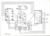
Diagram and description of operation.
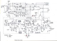

Four states can occur at the point X on the detection bridge C11, R5, depending on what is currently connected to the "Dx" input.
"O" ---- nothing is connected to the Dx input, the voltage at point X is 0V
"+" ---- correctly connected LED to Dx input, positive voltage at point X
"-" ---- inversely connected LED to DX input, negative voltage at point X
"~" ---- input Dx shorted or LED connected with parallel protection diode, AC voltage is present at point X.
The mini-tables in the diagram show the voltages at the most important points of the system corresponding to the states at point X.
Basically, these tables explain the principle of operation, but the system as a whole has a slightly twisted logic of operation, so the description is in order.
State "O", voltage 0V in point X, nothing connected to the Dx input.
At the input 2 (A) (amplifier A) 0V, at the output 1 (A) positive voltage thanks to the appropriately set voltage at the non-inverting input (PP test point). Transistors T1 and T2 conduct, there is no voltage on their collectors, transistor T3 does not conduct and does not turn on the relay P1, the green indicator D19 is not supplied from the collector T2 through the diode D13.
Also 0V at input 6 (B), negative voltage at output 7 (B) (it is ensured by a properly selected voltage at the non-inverting input 5 (B) using resistors R11, R12), the red indicator D18 is off.
The T5 transistor is conductive because its gate is + 8.5V, but only a very small current flows through it, limited by the high internal resistance of the voltmeter. Due to the relatively very low resistance R26 and R27, the voltage across these resistors is practically 0V. Transistor T4 is non-conductive.
The voltmeter shows the direct voltage that is currently switched on with the W1 switch.
The 0V voltage from the R26 resistor on input 2 (C), on the output 1 (C) + 7V, and then, after negation by the amplifier D, on output 7 (D) is 0V, the D19 indicator is not powered by the D14 diode, the buzzer is not powered, and there is no holding voltage for the conduction of transistor T3 from output 7 (D) by diode D15.
State "+", positive voltage in point X, tested LED connected correctly to input Dx.
Positive voltage on inputs 2 (A) and 6 (B) resulting from detection by the tested diode of AC voltage from the transformer.
The status of output 7 (B) will not change, the red diode D18 is off, informing about incorrect connection of the tested LED.
The voltage at output 1 (A) will change to negative, transistors T1 and T2 are clogged, on their collectors the supply voltage (+ 8.5V).
Green indicator light, the D19 diode is lit with a slightly weaker light, supplied from the T2 collector by the resistor * R18, diode D13 and the resistor R20 selected for the required brightness. The LED with a weaker light informs that the relay will be turned on in a moment and the tested LED will be connected to the selected DC voltage in series with the adjustable current source T4, T5.
At the same time, the voltage from the collector T1 is supplied by the diode D11 and the delay circuit R16, C13 (delay time 1 second) to the gate of the transistor T3 and after the delay time relay P1 will be turned on. The LED is switched to direct voltage, and the current flows through it, set by the R27 regulator.
The voltmeter will show the voltage on the LED under test.
The voltage of about 0.61V is deposited on the resistors R26 and R27, always the same, regardless of the current, when the current source is fully driven.
This voltage (0.61V) is detected by the input 2 (C), 0V appears on the output 1 (C) and after negation, the voltage + 6.3V appears on the output 7 (D), which maintains the T3 transistor's conduction.
The moment when the backup voltage appears (the relay is turned on) is signaled with a short sound signal by means of a buzzer connected through the C14 capacitor. At the same time, the output 7 (D) is powered by the diode D14 and the resistor R20, the green indicator D19. It now shines with full light, informing about the current flow through the tested LED, determined by the regulator R27.
At the moment of switching the relay, transistors T1 and T2 start to conduct because the variable voltage is disconnected from the tested LED, and thus the positive voltage at point X disappears.
The voltage on collectors T1 and T2 disappears, but the voltage on gate T3 does not disappear immediately. It is determined by the diode D11, the resistor R17 and the capacitors C12 and C13.
The time of voltage decay at the T3 gate is longer than the speed of the relay operation, the holding voltage from the output 7 (D) ensures uninterrupted activation of the T3 transistor and the relay. The D12 diode accelerates the disconnection of direct voltage from the test terminals (from the Dx input) after disconnecting the tested LED.
State "-", negative voltage at point X, tested LED connected inversely.
On inputs 2 (A) and 6 (B), negative voltage resulting from detection by the tested diode of AC voltage from the transformer.
Positive voltage at output 1 (A), then in this chain similarly to state "O".
On the other hand, the state of output 7 (B) will change from negative to positive, and the red diode D18 will light up, informing about incorrect connection of the tested LED.
Nothing else happens. The tested LED is not connected to DC voltage.
State "~", point X is variable voltage, input Dx shorted, or connected LED with parallel protection diode.
Variable voltage on inputs 2 (A) and 6 (B) causes square wave to appear on outputs 1 (A) and 7 (B).
The square wave will also appear on the collectors of transistors T1 and T2. Under the influence of these waveforms, both LEDs D18 and D19, green and red, in one housing will light, giving the resultant orange light, slightly darker.
The square wave from collector T1 is rectified by diode D11, and the rectified voltage across capacitor C12 turns on transistor T3 after a delay of 1 second.
Further in this string, as for the "+" state. The green D19 will light up fully, signaling the flow of the set current through the LED, and then this LED is on, or the flow of the same current through the protection diode and then the tested LED is off.
In each case, the voltmeter will show the appropriate voltage on the tested element because after switching the relay on, the voltmeter is connected in parallel to the Dx input. In case of shorted terminals it will show 0V.
The orange light, the result of the two LEDs D18 and D19, as well as the green light from D19 informs that the relay will turn on in 1 second, but it also gives an idea of what is connected to the Dx input. It also gives sufficient time to withdraw the test tip in case of doubt about the correct (safe) connection.
The current source on transistors T4 and T5 (in such a simple embodiment) has a certain inertia due to the fact that the transistor T5 is constantly in the conductive state because the resistor R29 is connected to the supply voltage. This makes it very easy to connect a voltmeter.
First, after connecting the tested element, a high current pulse will flow before the transistor T4 regulates the current flowing through T5. This "inertia" is also influenced by mounting capacities.
The inductance of L1 and L2 causes the current to "slowly rise" from the zero value to the set value. The speed of the current rise is much slower than the stabilization speed of the T4 and T5 transistors.
At the beginning I did not foresee the necessity to use these chokes and a few small diodes were burned when properly connected in the higher voltage range. After installing the chokes, this phenomenon was no longer present. The inductance of the coils is significant, comparable to the inductance of the relay winding, the diodes D5 and D6 are used to suppress the voltage pulse of self-induction at the moment of interrupting the current, when disconnecting the measuring tips.
The coils come from the NS and OW correction circuits of some CRT TV.
The destructive factor is not the voltage applied to the LED in the reverse direction, but the thermal action of the current after exceeding the permissible reverse voltage (the aforementioned "bad Zener diode"). High resistance R3 and R3a limits the current flowing through the tested LED to a value that is not dangerous for the internal structure. This resistance should be as high as possible, several tens of megohms at an alternating voltage of ~ 200V. However, for practical reasons and the adopted system assumptions, it was necessary to choose a safe compromise value for this resistance and other elements cooperating with amplifiers A and B.
Resistors R3, R3a, R4 and the capacitor C11 are the main divider of ~ 200V alternating voltage, decisive for the voltage level at point X.
Resistor R5 has little effect on this voltage, it is mainly used to discharge the capacitor C11. With the capacitor C11 = 47nF and R3 + R3a = 15M, the voltage value at point X is the highest for the experimentally selected value of R5 = 235k (470kII470k).
Zener diodes D7, D8 protect against possible high voltage penetration, e.g. short circuit or moisture or misting up of the resistors R3, R3a.
For a frequency of 50 Hz, the capacitive resistance Xc for various (example) capacitors is:
C = 10nF, Xc = 318k
C = 20nF, Xc = 159.23k
* C = 47nF, Xc = 67k
C = 0.1uF, Xc = 31.8k
Compared with the large resistance R3 + R3a = 15M, the resistance of Xc = 67k of the capacitor C11 = 47nF is very small.
For this, you can omit all those roots and squares resulting from the triangle of resistance, it can be assumed that this is a linear divider that determines the voltage at X.
The voltage set by the resistor R8 at the measuring point PP, at the non-inverting input 3 (A), sets the correct threshold for the operation of amplifier A (basically it is a Schmitt trigger with an adjustable threshold).
The value of the set voltage at point PP depends on what voltage is expected at point X and what priority is currently (or most often) needed.
Capacitor C11 with a smaller capacity, e.g. 10nF or 20nF, the higher voltage rectified at point X, then resistors R3 with a greater value can be used, even up to 40M, but the voltage after rectification is very slightly smoothed, very pulsating very strongly. The system well detects a larger number of LEDs with parallel protection diodes.
The sensitivity increases and the influence of the inducing disturbances in the (long) measuring cable going to "--Dx" is noticeable. Touching the insulation of this wire with your hand activates the relay, you need to lower the sensitivity significantly (increase the voltage at the point PP), and this causes bad work with more LEDs with protective diodes.
The large capacity of the capacitor C11, eg 0.1 uF, is the voltagelow value rectified very well smoothed, so that no more LEDs with a protection diode can be detected well. You need to reduce R3 to a value even less than 10M which is not safe for LED, and lower the voltage value at PP.
Completely insensitive to interference from long test leads.
The capacitance of the C11 capacitor should be selected so that after the Dx output is short-circuited at point X, there is an alternating voltage that allows the threshold to be exceeded and the relay to be activated. This allows, for example, to check the course and continuity of paths in the rulers. The threshold must not be too small, because then there will be no good protection, at the same time it cannot be too large, because then the protection will work very well, but it will not be possible to light more LEDs with protective diodes, e.g. only two or three, instead of the entire a long line, which is very necessary (e.g. 15 LED "3V").
The conclusion is that the voltage at point X, apart from the DC component after straightening, must also have a sufficiently large variable component.
The values of all elements from the environment A and B, on the schematic diagram, have been selected experimentally, optimally, after quite tedious tests with about a hundred different LEDs, and various lines (strings) from the TV backlight, primarily taking into account the easy and safe search for the damaged LED in the ruler .
Voltage at the PP test point.
The test point PP is led out to the rear wall, and the variable resistor R8 is accessible through the opening in the top of the housing.
To set / calibrate the tester, turn on the + 290V voltage with the W1 switch, and set the R8 resistor so that the highest voltage is at the point PP (about 1.6V). Then short the Dx input, and slowly reducing the voltage at the point PP with the resistor R8, cause the relay to turn on. The green indicator D19 will light up, there will be a short beep. For such values of elements as in the diagram, it will be a voltage of 1.30V. To make sure it works, lower it to 1.25V.
Such a setting (1.25V) allows for reliable and error-free detection of incorrect connection to the "Dx" sockets on the + 290V range, single LEDs with even the worst parameters (with an acceptable reverse voltage of 15V).
The greater the number of LEDs in the series, the better the quality of the resultant diode "Dx", the greater the difference between the resultant blocking voltage and the resultant forward voltage, the error possibility is reduced.
Despite the existence of automation, you shouldn't take risks unnecessarily. A single LED should be checked at a low voltage of + 8.5V, then there is no risk even with the automation turned off. We are talking about LED all the time without parallel protection diodes.
When it is known in advance that we are dealing with a LED with a parallel protection diode, all this automatics can be turned off (switch W2) and not bother with it. You just have to be careful not to accidentally "get on your toes".
As a rule, LEDs with protective diodes are used in TV backlights. For your own convenience in searching for a damaged LED in a specific line, however, it is not worth turning off the protection, but lowering the voltage at the point of PP in such a way that you can light up even the longest line (not the entire backlight). In this particular case, at a voltage of 0.95V, 17 LEDs "3V" or 8 LEDs "6V" can be lit.
Such a compromise setting of the threshold permanently introduces some limitation, not convenience in use. So I made a small change later. The single two-position switch W2 has been replaced with a three-position double switch, and the red LED D20 has been replaced with a double red / green LED D21, D22.
When the W2 switch is in the middle position, at the point PP, the maximum threshold voltage (+ 1.25V) is set with the resistor R8. D21 and D22 LEDs are off.
When the W2 switch is in the lower position (on the diagram), the automation is off, the red LED D21 lights up.
When the switch W2 is in the upper position, a variable resistor R33 is connected parallel to the point PP, which sets the minimum allowable threshold voltage in such a way that the tester is not sensitive to touching / grasping the wire insulation "-Dx".
In this particular case it is + 0.159V. D21 and D22 LEDs are illuminated simultaneously giving orange light. The resistor R32 selects the appropriate color.
This setting allows you to connect a large number of LEDs with a parallel protection diode while protecting against electric shock with + 290V.
Resistor R33 mounted on the back wall of the case, next to point PP, and is accessible through a hole in the top of the case.
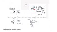

Lowering the threshold means that the protection may not work when testing (at + 290V) single ordinary LEDs with a very low reverse voltage. It works well for two or more in a row, because the "quality" of the resultant Dx diode increases.
As I wrote above, single diodes should be tested at low voltage without any risk.
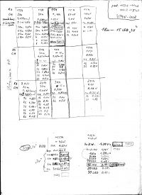
Transformer and housing.
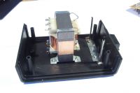
The TSL15 / 001 type mains transformer was found that best suited the assumptions. It has two secondary windings: ~ 200V and ~ 6.3V, which after rectification gives the voltage of + 290V, + 8.5V and --8.5V, respectively. The third winding to power the voltmeter had to be wound.
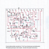
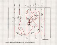
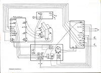
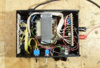
The choice of the transformer forced the choice of the Z-3 / B type casing (dimensions 150x110x70 mm), and the casing and the transformer, in turn, forced the dimensions of the plates and the way they were mounted, as well as the length and routing of cable bundles / ribbons.
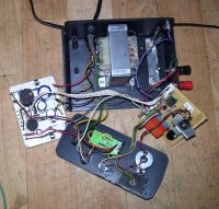
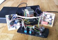
Everything is clearly visible in the photos.
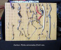
The length of the cables and the way of mounting the plates allows you to conveniently remove the front plate and plates, e.g. for repair. The PSU board is mounted on the housing posts by means of soldered metal plate rings, the second board is inserted into a special stand.
The TSL15 / 001 transformer has a central column with dimensions of 2.3x2.3 cm, where the cross-section of 5.9 cm comes from.
For this core cross-section, 8 zw / V are obtained. Proven, practical formula for determining the number of turns per 1V:
45 / S where S is the cross-section of the middle column of the core in [cm?].
To power the voltmeter, it is enough to wind 35 turns. I wound a bit more, because 54 turns, that's how much fit in one layer of wire with a diameter of 0.3 mm, and I used 40 turns, which after straightening gave 6V. For this there is a resistor R1 in the power supply of the voltmeter so as not to unnecessarily load the stabilizer in the voltmeter.
The remaining 15 turns were later connected in series with the 6.3V winding, which raised the rectified voltage from 8.5V to 10.5V. This influenced the work of the tester only so much that on a lower voltage, instead of three "normal" LEDs, four can be lit. It did not affect the operation of the relay or the current source.
Of course, winding up without taking the core apart is a bit tedious, but it can be done with a little patience.
Before starting the winding, cut the copper shielding plate (on each side) and fold it. Windows and the sheet of the core should be covered with e.g. masking tape in order not to damage the wire insulation. Apply double-sided adhesive tape to the existing winding on both sides, it will hold the windings.
You need to measure the length of one turn and measure the required length of the wire. It will be about 7.5 m. The wire cannot be wound on anything, it must lie loose. All protruding objects must be removed around the table / stand so that the wire does not get caught and threaded, threaded and threaded again. Each threading is half a coil, it must be blocked with a flexible wedge, e.g. made of a sheet of paper folded several times, to prevent the rolls from falling apart. Change the wedge to the other side after each threading.
The ends of the winding should be soldered to the eyelets made of wire fused in the carcass on the opposite side of the factory terminals.
After securing the winding with insulating tape, solder the cut shielding plate. You can not solder the entire cut, but only one point with a piece of wire.
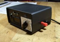

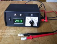
Voltmeter and faceplate.
The voltmeter should be at least 4 digits long and with a measuring range of at least 300V. Ideally, one would be one with auto range, with a variable decimal point. Unfortunately, I have not found such properties, cheap and small.
A four-digit voltmeter with a range of up to 30V was used, with a fixed decimal point after the second digit, after appropriate adaptation:
http://allegro.pl/woltomierz-cyawod-panelowy-30v-zielony-4-znakowy-i5128606564.html#imglayer
The permanently lit second point was painted with black paint, and in the place of the third point a miniature green SMD LED, size 0603, was mounted on thin wires. The SMD resistor (1206) 30k in series with the diode. If necessary, you must choose a different value of this resistor so that the brightness of the point does not differ from the brightness of the digits. Everything is connected to the pins supplying the voltmeter system. The wires holding the diode are taped to the side of the display.
Soldering wires to such a small diode can be a challenge. This is best done as follows. Plan the direction of the diode connection at the beginning, so as not to cross the wires later. Fasten the tinned wire in a vice or other tripod,Hold the diode with flat pliers / tweezers in order to dissipate heat, put it on the wire and with a short, quick touch of the soldering iron, solder.
Converting the point electronically is not an option due to the construction of this voltmeter.
To extend the range from 30V to 300V, a serial SMD resistor (1206) with a value of 1M was enough, connected with an insulated wire (300V!) To the path crossing from the input pin + Vin.
In this case it turned out that no additional regulating resistor is needed. The accuracy (0.1V) is sufficient for both low and high voltage values.
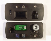
The conversion of the voltmeter is clearly visible in the photos.
The voltmeter board fits very precisely into the housing. The thickness of the mounted LED is only 0.4 mm, but in order not to break the glass (it happened and it was necessary to cut a new one), you have to saw the lugs fixing the plate with this distance.
Dimensions of the voltmeter 48x29x22 mm, dimensions of the mounting hole 46x27 mm.
The voltmeter also serves as an indicator of connecting the tester to the mains, showing the voltage that is always on, so there is no ON indicator on the front panel.
The voltmeter is mounted on the lower edge of the faceplate, under the switches for ergonomic reasons. You can rest your fingers comfortably on the housing and switch.
A double red-green LED (D18, D19) with a diameter of 8 mm is pressed into a slightly smaller hole in a 2.5 mm thick rubber strip, the rubber is glued to the plate. Red LED D20 with a diameter of 3 mm, pressed directly into the hole in the board, next to the automatic switch.

Potentiometer and scale.
The current source current control on T4 and T5 transistors is made with a wire potentiometer R27 with a value of 100?. Potentiometers with the values of 50 ?, 100 ? and 150 ? have been practically tested. The 100? potentiometer turned out to be the most optimal. With this value, the minimum current value is 5mA, and not too much non-linear scale in the range of higher currents. At 150?, the minimum value is 4mA, and the scale is very tightly stretched in the low current range and compressed in the high current range. At 50?, the minimum current is 11mA, which is too much but the scale is less non-linear.
The maximum current (assuming 200mA) is determined by the selected resistor R26 with a value of 2.68? (1 + 1 + 0.68). Resistor R26 is not heavily loaded due to its value, it can be of very low power, even SMD type if necessary.
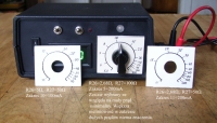
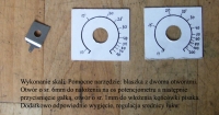
A scale made of thicker paper is under a 2mm thick transparent cover. A large knob with an indicator allows you to set the current (even before connecting to the mains) with high accuracy in the range of up to 15mA and good accuracy from 15 to 30mA. Above these values, the accuracy in such a tester is not important, it is enough that it is possible to check the tested LEDs for a few seconds with the maximum current.
Scaling is drawing appropriate lines under the indicator of the knob after shorting the "Dx" input with a milliammeter and reading the value of the set current.
At the beginning, the lines should be slightly drawn with a pencil and the scaling operation repeated several times, taking into account the parallax error.
The nut securing the potentiometer must be filed round.
Adjust the hole in the transparent cover and the necessary dimensions of the cover itself in such a way that the nut fits into the hole, and the cover with its lower edge rests against the bottom of the housing as far as possible.
In the scale paper, with dimensions larger than the cover, make a hole and adjust the lower edge so that it is flush with the lower edge of the faceplate, it fits into the recess in the lower part of the housing. After applying the transparent cover, you can cut the paper exactly with the cover.
The knob presses the cover and the scale with a fitted / sawn fiber slip ring from the water seal. The ring prevents the knob from rubbing against the glass.
Such a design will allow for error-free re-setting of the scale in the event of disassembly.
Demo pics.


