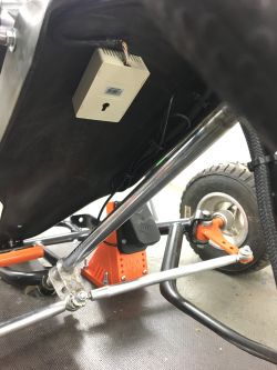
The idea came from the fact that the 5-year-old daughter is willing to drive all kinds of vehicles. He packs on a motorcycle, he wants to drive the car, he stays in the tractor with his grandparents, etc.
So I decided to build something for her that would allow to develop certain habits of the driver and provide a dose of adrenaline and child's fun. The idea fell on a go-kart. However, the noise or the risk of being scalded by an internal combustion engine, the lack of my control over the stopping of such a vehicle in an emergency, prompted me to switch to an electric drive. Remote (radio) disconnection of such a drive seems to be easier. It is also possible to regulate the speed or acceleration.
There are no special assumptions about power or speed.
While searching OLX, I found a go-kart close to my place of residence. Unfortunately, it turned out that it was in parts and the fact that I bought it was the biggest mistake during the whole construction. Few things fit, I got a pile of parts from the seller, probably of various designs, heavily damaged and often thrown away.
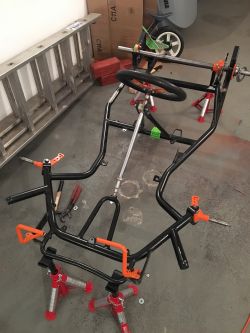
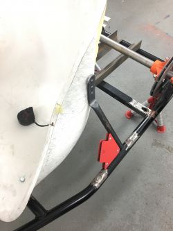
The frame was already powder coated black, which was not quite ok. I had a lot of welding modifications to do, so I will have to re-paint it anyway.
The first move was the cutting of the internal combustion engine, seat and steering wheel supports. I wanted the seat and the steering wheel to be centrally located in relation to the frame, and not, as in the exhaust fumes - moved away from the vehicle axis. The drive was to be installed centrally behind the driver's seat.
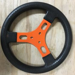
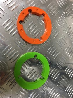
Also trivial things like painstaking cleaning of elements, then painting them orange, because that's what my daughter chose or printing some of the items took a long time.
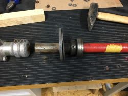
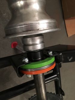
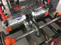
I will use two 2.2kW series-shunt motors for the drive. They have one huge drawback, their S2 performance characteristics are 1.2Min at S3 = 4%. Previously, they worked in battery-powered palletizing trucks, driving hydraulic lifting pumps.
So it will be necessary to add forced cooling. During the tests, it turned out that the motors heat up the most around the commutator. So that's what I'm going to focus on and cut openings in the cover, additionally forcing the airflow with the fan.
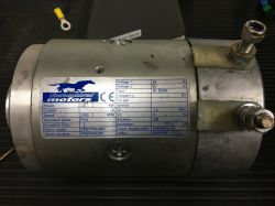
I placed the motors opposite to each other, which involved a slight modification of one of them so that it rotated in the opposite direction. Both, being identical, have CW speed ex works. In my case, the change was to change the polarity of the stator windings.
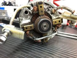
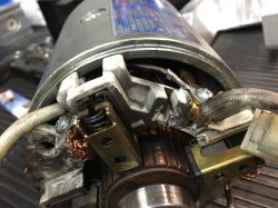
After a surprise modification, it turned out that the engine consumes twice the current at idle speed compared to the second engine. Suspicion fell on the brushes that were not torn in this direction. And probably in fact, this was the reason, because after treating the brushes with sandpaper wound on the commutator and then several minutes of work at idle speed, the current decreased significantly, but it is still greater than its twin brother. At maximum speed, the engine without modifications consumes about 16A. Engine after modifications about 22A. Perhaps still a cracked housing, and at the same time the bearing housing is affected. It is already welded, but the tests are not done today.
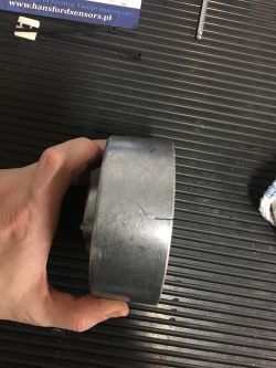
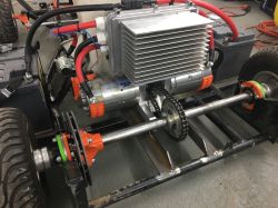
The motors will be mechanically coupled to each other. A gear rack will be installed on the clutch.
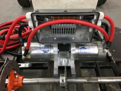
The engine mounting block made as a monolith. In addition, a great place to screw the PWM controller housing. The engine block will be bolted to the rails of angles with the possibility of sliding for tensioning the chain.
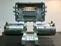
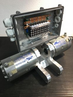
Driver only purchased on e-bay. According to the manufacturer 200A, we'll see.
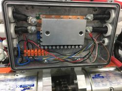
The aluminum housing is also to serve as a heat sink. Unfortunately, the controller's adjustment potentiometers are located on the same side as the originally installed piece of aluminum, the heat sink. It would be much better to screw the driver to the housing with a heat sink, but well. I am going to choose an aluminum beam in such a size that after screwing the cover it can still be screwed to the heat sink. Trouble opening, but a compromise must be found.
The above-mentioned potentiometers can be used to set the maximum current, the battery charging current in the case of regeneration mode and the acceleration ramp.
The controller can work in regeneration mode. I don't know what it will look like while driving, if the motors will be a "good" brake and some of this energy can be returned to the battery, but I intend to use this function.
A very provisional test of the driver on one engine.
Batteries. Many similar DIY designs I have seen have cells in use, e.g. lithium-ion.
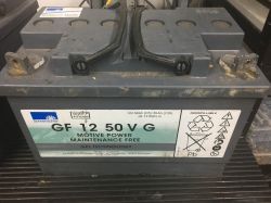
For me, these will be ordinary, heavy, two 12V 50Ah gel traction batteries. One weighs 20 kg according to the manufacturer, a massacre. I hope, however, that it is enough to have fun and you can "go crazy" these several dozen minutes to an hour.
Successful try-on of the power unit.
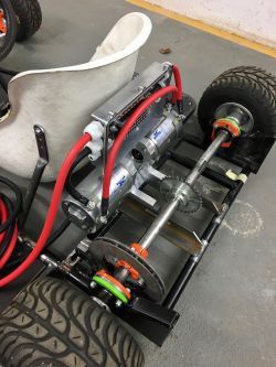
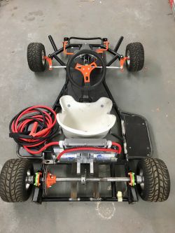
A floor made of waterproof plywood must suffice for now. Its edge in the photos is exposed after cutting, but when the go-kart is disassembled for painting, the plywood will be painted as well. There will be batteries on the shelves on the sides of the go-kart.
Accelerator pedal mounted on a printed bracket, of course the right color.
As I am writing this, the brake pedal and its mounting are also printed.
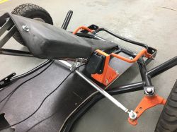
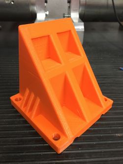
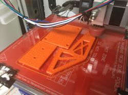
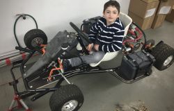
The vehicle is at the stage as shown in the photos. Roughly quite a lot to complete.
Electrical system, brake, engine clutch, engine cooling, maybe lighting. To weld in the roll bar behind the driver, in the case of a flip. Most likely something ala seat belts too. Of course, remote radio shutdown of the drive. From time to time, I am going to post photos of the progress of work, as long as I have to finish it.
2018-04-11
After a long break, it's time for a few words what you managed to do.
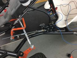
Following the advice of Euzebiusz23091998, I made a steel brake. So far, it is only a cable with a pump attached, waiting for the clamp, and a limit switch to disconnect the contactor during braking and in the future, to turn on the regeneration and maybe the STOP light.
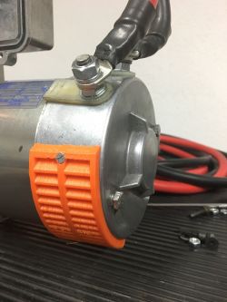
In the meantime, engine cooling was added. I attached a 24V fan, which is doing quite well through a few holes in the cover. During the tests, driving around 15 minutes, the engines were only warm.
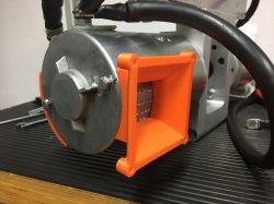
We also managed to install the electrical installation and make a switch panel for the driver.
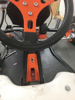
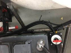
I also installed a remote control module. The main contactor can now be switched off with the remote control in the event of "w".
PROBLEMS!
During the tests, it turns out that there is a lot of room for improvement.
The kart does not "pull" as I would expect. I'm disappointed.
The controller becomes very hot. The resistance to turning, resulting from the lack of a differential and a lot of weight on the rear axle, means that this stroller is barely pushed when the front wheels are turned. Thus, the controller and the motors have something to do. When driving slowly, this negative effect only gets worse. When driving straight ahead, the go-kart runs very lightly.
After consulting the forum on electric cars, I'm going to convert the drive. The axle will be cut in half, the motors will be decoupled and each motor will be individually
drive one rear wheel of the go-kart. This is to give the effect of a limited slip differential.
A large heat sink will also be installed for the driver. Even though the manufacturer says 200A for his work, I am beginning to have some doubts.
Additionally, a seat to lift, at least 20mm. Now, on unevenness, often the "chair" strokes the street.
Accelerator pedal. As I purchased a hall effect pedal, another problem arose. On an ordinary potentiometer, during tests, the controller stopped the engine at the extreme position of the resistor. The motor current was dropping to zero. Unfortunately, this is not the case with Hall. Despite the extreme position, the controller supplies voltage to the motors and they start spinning. It turns out that the hall gives some voltage in its minimum position, so the controller reacts to it. Unfortunately, the controller itself does not have any regulation for this parameter. I don't know what to do, whether to add a switch that detects the beginning of the pedal's movements and only then gives the control voltage, or to buy a potentiometer pedal. For now, the brake pedal disconnects the main contactor, so you can stop the go-kart, but just release it for the wheelchair to slowly roll.
Despite the fact that it is not perfect, the young one likes it.
So I decided to build something for her that would allow to develop certain habits of the driver and provide a dose of adrenaline and child's fun. The idea fell on a go-kart. However, the noise or the risk of being scalded by an internal combustion engine, the lack of my control over the stopping of such a vehicle in an emergency, prompted me to switch to an electric drive. Remote (radio) disconnection of such a drive seems to be easier. It is also possible to regulate the speed or acceleration.
There are no special assumptions about power or speed.
While searching OLX, I found a go-kart close to my place of residence. Unfortunately, it turned out that it was in parts and the fact that I bought it was the biggest mistake during the whole construction. Few things fit, I got a pile of parts from the seller, probably of various designs, heavily damaged and often thrown away.


The frame was already powder coated black, which was not quite ok. I had a lot of welding modifications to do, so I will have to re-paint it anyway.
The first move was the cutting of the internal combustion engine, seat and steering wheel supports. I wanted the seat and the steering wheel to be centrally located in relation to the frame, and not, as in the exhaust fumes - moved away from the vehicle axis. The drive was to be installed centrally behind the driver's seat.
Also trivial things like painstaking cleaning of elements, then painting them orange, because that's what my daughter chose


I will use two 2.2kW series-shunt motors for the drive. They have one huge drawback, their S2 performance characteristics are 1.2Min at S3 = 4%. Previously, they worked in battery-powered palletizing trucks, driving hydraulic lifting pumps.
So it will be necessary to add forced cooling. During the tests, it turned out that the motors heat up the most around the commutator. So that's what I'm going to focus on and cut openings in the cover, additionally forcing the airflow with the fan.

I placed the motors opposite to each other, which involved a slight modification of one of them so that it rotated in the opposite direction. Both, being identical, have CW speed ex works. In my case, the change was to change the polarity of the stator windings.


After a surprise modification, it turned out that the engine consumes twice the current at idle speed compared to the second engine. Suspicion fell on the brushes that were not torn in this direction. And probably in fact, this was the reason, because after treating the brushes with sandpaper wound on the commutator and then several minutes of work at idle speed, the current decreased significantly, but it is still greater than its twin brother. At maximum speed, the engine without modifications consumes about 16A. Engine after modifications about 22A. Perhaps still a cracked housing, and at the same time the bearing housing is affected. It is already welded, but the tests are not done today.

The motors will be mechanically coupled to each other. A gear rack will be installed on the clutch.
The engine mounting block made as a monolith. In addition, a great place to screw the PWM controller housing. The engine block will be bolted to the rails of angles with the possibility of sliding for tensioning the chain.


Driver only purchased on e-bay. According to the manufacturer 200A, we'll see.
The aluminum housing is also to serve as a heat sink. Unfortunately, the controller's adjustment potentiometers are located on the same side as the originally installed piece of aluminum, the heat sink. It would be much better to screw the driver to the housing with a heat sink, but well. I am going to choose an aluminum beam in such a size that after screwing the cover it can still be screwed to the heat sink. Trouble opening, but a compromise must be found.
The above-mentioned potentiometers can be used to set the maximum current, the battery charging current in the case of regeneration mode and the acceleration ramp.
The controller can work in regeneration mode. I don't know what it will look like while driving, if the motors will be a "good" brake and some of this energy can be returned to the battery, but I intend to use this function.
A very provisional test of the driver on one engine.
Batteries. Many similar DIY designs I have seen have cells in use, e.g. lithium-ion.
For me, these will be ordinary, heavy, two 12V 50Ah gel traction batteries. One weighs 20 kg according to the manufacturer, a massacre. I hope, however, that it is enough to have fun and you can "go crazy" these several dozen minutes to an hour.

Successful try-on of the power unit.


A floor made of waterproof plywood must suffice for now. Its edge in the photos is exposed after cutting, but when the go-kart is disassembled for painting, the plywood will be painted as well. There will be batteries on the shelves on the sides of the go-kart.
Accelerator pedal mounted on a printed bracket, of course the right color.
As I am writing this, the brake pedal and its mounting are also printed.


The vehicle is at the stage as shown in the photos. Roughly quite a lot to complete.
Electrical system, brake, engine clutch, engine cooling, maybe lighting. To weld in the roll bar behind the driver, in the case of a flip. Most likely something ala seat belts too. Of course, remote radio shutdown of the drive. From time to time, I am going to post photos of the progress of work, as long as I have to finish it.
2018-04-11
After a long break, it's time for a few words what you managed to do.
Following the advice of Euzebiusz23091998, I made a steel brake. So far, it is only a cable with a pump attached, waiting for the clamp, and a limit switch to disconnect the contactor during braking and in the future, to turn on the regeneration and maybe the STOP light.

In the meantime, engine cooling was added. I attached a 24V fan, which is doing quite well through a few holes in the cover. During the tests, driving around 15 minutes, the engines were only warm.


We also managed to install the electrical installation and make a switch panel for the driver.


I also installed a remote control module. The main contactor can now be switched off with the remote control in the event of "w".
PROBLEMS!
During the tests, it turns out that there is a lot of room for improvement.
The kart does not "pull" as I would expect. I'm disappointed.
The controller becomes very hot. The resistance to turning, resulting from the lack of a differential and a lot of weight on the rear axle, means that this stroller is barely pushed when the front wheels are turned. Thus, the controller and the motors have something to do. When driving slowly, this negative effect only gets worse. When driving straight ahead, the go-kart runs very lightly.
After consulting the forum on electric cars, I'm going to convert the drive. The axle will be cut in half, the motors will be decoupled and each motor will be individually
drive one rear wheel of the go-kart. This is to give the effect of a limited slip differential.
A large heat sink will also be installed for the driver. Even though the manufacturer says 200A for his work, I am beginning to have some doubts.
Additionally, a seat to lift, at least 20mm. Now, on unevenness, often the "chair" strokes the street.
Accelerator pedal. As I purchased a hall effect pedal, another problem arose. On an ordinary potentiometer, during tests, the controller stopped the engine at the extreme position of the resistor. The motor current was dropping to zero. Unfortunately, this is not the case with Hall. Despite the extreme position, the controller supplies voltage to the motors and they start spinning. It turns out that the hall gives some voltage in its minimum position, so the controller reacts to it. Unfortunately, the controller itself does not have any regulation for this parameter. I don't know what to do, whether to add a switch that detects the beginning of the pedal's movements and only then gives the control voltage, or to buy a potentiometer pedal. For now, the brake pedal disconnects the main contactor, so you can stop the go-kart, but just release it for the wheelchair to slowly roll.
Despite the fact that it is not perfect, the young one likes it.


Cool? Ranking DIY


