And I am again my dear. This is another article today devoted to a simple Chinese toy for self-assembly. This time we have a "police strobe" on the wallpaper.

It is a gadget for six and a half Polish zlotys, which, like the electronic hourglass that has just been described, has no practical use. Well, maybe if the diodes were replaced with the colors permitted by the law, a bicycle lamp would come out of it.
The most you can do is practice your soldering iron. It is quite difficult to solder, because the manufacturer did not whiten the soldering points or protect them with anything. So we have bare copper. Actually not, because it is covered with oxides that hinder soldering.
This time, after assembling the system, I had four diodes, but there was no electrolytic capacitor.
As always, the assembly of the system starts with the lowest elements and ends with the highest ones. First things first. Let's see what we get in the package:
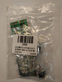
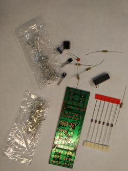
We have a set of items.
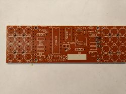
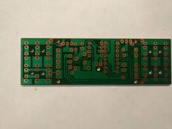
And a PCB.
I would like to draw your attention to the resistors R2 and R3. They are not described on the board. The reason is simple, they are responsible for the brightness of the LEDs. As red LEDs require a different current than blue LEDs, you should remember about this detail.
You should also pay attention not to go too far when mounting the LEDs, because two of them are mounted "inversely".
The kit includes:
1. The said PCB.
2. Immortal NE555 chip.
3. CD4017BE chip.
4. Two S8050 transistors (I see majfrends, they pack them wherever they can).
5. Six LEDs with unknown designation (they look like regular 1m4148).
6. Several different resistors.
7. 1uF capacitor (which I lacked).
8. 200kOhm mounting potentiometer. To adjust the flash speed.
9. The system is powered by the voltage 0d 9VDC to 12VDC. We supply power to the visible goldpins, which the manufacturer did not care for.
10. We also have two times twelve (I had three blue and one red in excess) quite bright LEDs.
11. The dimensions of the board are 94mm x 29mm.
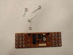
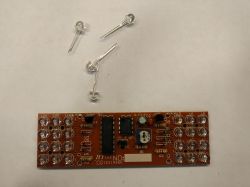
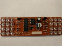
Assembled system.
The board has a perforation and we can break off parts with LEDs. There are also holes with power soldering pads when we wanted to break off the "LED panels".
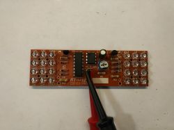
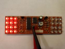
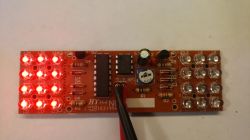
Something non-photogenic, these blue flashes.
Now for some movies.
[movie: 6110cf8d28] https://filmy.elektroda.pl/35_1525173370.mp4 [/ movie: 6110cf8d28]
[movie: 6110cf8d28] https://filmy.elektroda.pl/55_1525173421.mp4 [/ movie: 6110cf8d28]
[movie: 6110cf8d28] https://filmy.elektroda.pl/30_1525173455.mp4 [/ movie: 6110cf8d28]
To sum up, it is another gadget dedicated to the youngest electronics beginner. If instead of blue LEDs we solder only the red ones, we can have a rear bicycle light. If white, then front. You can also solder the white and red ones, and then break the plate into two or three parts. For this some clever housing made of transparent plastic, possibly covered with colorless glue or silicone, and how much fun we have. No bicycle shop light has a smooth adjustment of the frequency of flashes. You can show off on the brave. :)
Best regards.
CMS

It is a gadget for six and a half Polish zlotys, which, like the electronic hourglass that has just been described, has no practical use. Well, maybe if the diodes were replaced with the colors permitted by the law, a bicycle lamp would come out of it.
The most you can do is practice your soldering iron. It is quite difficult to solder, because the manufacturer did not whiten the soldering points or protect them with anything. So we have bare copper. Actually not, because it is covered with oxides that hinder soldering.
This time, after assembling the system, I had four diodes, but there was no electrolytic capacitor.
As always, the assembly of the system starts with the lowest elements and ends with the highest ones. First things first. Let's see what we get in the package:


We have a set of items.


And a PCB.
I would like to draw your attention to the resistors R2 and R3. They are not described on the board. The reason is simple, they are responsible for the brightness of the LEDs. As red LEDs require a different current than blue LEDs, you should remember about this detail.
You should also pay attention not to go too far when mounting the LEDs, because two of them are mounted "inversely".
The kit includes:
1. The said PCB.
2. Immortal NE555 chip.
3. CD4017BE chip.
4. Two S8050 transistors (I see majfrends, they pack them wherever they can).
5. Six LEDs with unknown designation (they look like regular 1m4148).
6. Several different resistors.
7. 1uF capacitor (which I lacked).
8. 200kOhm mounting potentiometer. To adjust the flash speed.
9. The system is powered by the voltage 0d 9VDC to 12VDC. We supply power to the visible goldpins, which the manufacturer did not care for.
10. We also have two times twelve (I had three blue and one red in excess) quite bright LEDs.
11. The dimensions of the board are 94mm x 29mm.


Assembled system.
The board has a perforation and we can break off parts with LEDs. There are also holes with power soldering pads when we wanted to break off the "LED panels".


Something non-photogenic, these blue flashes.
Now for some movies.
[movie: 6110cf8d28] https://filmy.elektroda.pl/35_1525173370.mp4 [/ movie: 6110cf8d28]
[movie: 6110cf8d28] https://filmy.elektroda.pl/55_1525173421.mp4 [/ movie: 6110cf8d28]
[movie: 6110cf8d28] https://filmy.elektroda.pl/30_1525173455.mp4 [/ movie: 6110cf8d28]
To sum up, it is another gadget dedicated to the youngest electronics beginner. If instead of blue LEDs we solder only the red ones, we can have a rear bicycle light. If white, then front. You can also solder the white and red ones, and then break the plate into two or three parts. For this some clever housing made of transparent plastic, possibly covered with colorless glue or silicone, and how much fun we have. No bicycle shop light has a smooth adjustment of the frequency of flashes. You can show off on the brave. :)
Best regards.
CMS
Cool? Ranking DIY


