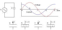
What happens when AC voltage is applied to the capacitor legs? This element behaves differently than a resistor - the resistor allows direct flow of electrons. The current through the resistor is, according to Ohm's law, proportional to the voltage drop across it. In the case of a capacitor, current is drawn in rhythm as the element charges and discharges to a new voltage level.
The capacitor charges up to the voltage applied to it. It acts as a kind of electricity store - as long as a direct voltage (DC) is applied to this element, it maintains its internal charge. When the voltage changes, a current will flow that will try to compensate for the change. The value of the current flowing will be directly proportional to the rate of change of the charge on the capacitor plates.
In the figure above, we can see a simple circuit - a capacitor connected to an AC voltage source (top left). In such a system, between the current (blue line) and the voltage (red line) flowing through the capacitor, we observe a phase shift of exactly 90 ° (?? - exactly 1/4 of the entire cycle of alternating voltage; top right).
The AC voltage changes cyclically. The greater the capacity of the connected capacitor, the greater the charge will accumulate between its plates, and thus the greater the current that will flow in the system. It will be similar when we increase the frequency of the alternating voltage - the higher it is, the faster the capacitor must charge, and thus the greater the current flowing in the system. Thus - the current depends on the capacitance of the capacitor and the frequency of the alternating signal.
Capacitive alternating current systems
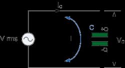
A fully capacitive AC system is one that consists only of an AC voltage source and a capacitor - as shown in the figure above. In this case, a single capacitor is directly connected to the voltage source. As the voltage changes at the source, the capacitor charges and discharges. Current flows through the system all the time - cyclically back and forth. However, no current actually flows through the capacitor. It is the electrons that concentrate first on one of the covers, and then flow through the system and concentrate on the other cover - at no time do they flow through the dielectric separating them, although this may appear to an inexperienced observer.
Capacitor reactance
The flow of electrons through the capacitor is directly proportional to the rate of change of voltage on the plates of this capacitor. Here, the proportionality factor is reactance, just like resistance is the proportionality factor of current and voltage in a system with a resistor.
The reactance is marked with the letter X to distinguish it from the normal resistance for DC voltage (R). However, like the resistance, its unit is the ohm [?]. The following equation describes the dependence of the reactance on the frequency of the alternating signal f (in Hertz) and the capacitance of the capacitor C (expressed in farads).
$$X = \frac {1} {2 \pi f C} = \frac {1} {\omega C}$$
As we can see in the above equation - the higher the frequency or capacity, the smaller the reactance and therefore the greater the current - exactly as described above.
Source: https://www.eeweb.com/profile/andrew-carter/articles/how-capacitors-behave-in-ac-circuits
Cool? Ranking DIY


