logo elektroda
logo elektroda
X
logo elektroda

ESP32-CAM FT232RL - no response after uploading CameraWebServer.ino

yarogniew 1662 15
ADVERTISEMENT
Treść została przetłumaczona polish » english Zobacz oryginalną wersję tematu
  • #1 18783975
    yarogniew
    Level 9  
    Hi. As usual, I am asking for help.
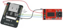
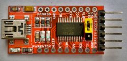
    I am uploading a typical program CameraWebServer.ino via Arduino IDE and programmer USB TO TTL FT232RL , Jumper on 3.3V, PIN0 connected to GND, ESP32 powered from programmer with 3.3V everything else as in hundreds of instructions on the net. I press reset on the board, get info on the monitor:
    14:02:22.730 -> rst:0x1 (POWERON_RESET),boot:0x3 (DOWNLOAD_BOOT(UART0/UART1/SDIO_REI_REO_V2))
    14:02:22.730 -> waiting for download
    
    .
    I upload the program, it loads elegantly. I get info Done uploading .
    I disconnect I0 from GND, press RESET and I get blocks like this displayed over and over again:
    
    14:11:21.606 -> 
    14:11:21.606 -> rst:0x3 (SW_RESET),boot:0x13 (SPI_FAST_FLASH_BOOT)
    14:11:21.640 -> configsip: 0, SPIWP:0xee
    14:11:21.640 -> clk_drv:0x00,q_drv:0x00,d_drv:0x00,cs0_drv:0x00,hd_drv:0x00,wp_drv:0x00
    14:11:21.640 -> mode:DIO, clock div:1
    14:11:21.640 -> load:0x3fff0018,len:4
    14:11:21.640 -> load:0x3fff001c,len:1216
    14:11:21.640 -> ho 0 tail 12 room 4
    14:11:21.640 -> load:0x40078000,len:9720
    14:11:21.640 -> ho 0 tail 12 room 4
    14:11:21.640 -> load:0x40080400,len:6352
    14:11:21.640 -> entry 0x400806b8
    14:11:22.225 -> ets Jun  8 2016 00:22:57
    14:11:22.225 -> 
    14:11:22.225 -> rst:0x3 (SW_RESET),boot:0x13 (SPI_FAST_FLASH_BOOT)
    14:11:22.225 -> configsip: 0, SPIWP:0xee
    14:11:22.225 -> clk_drv:0x00,q_drv:0x00,d_drv:0x00,cs0_drv:0x00,hd_drv:0x00,wp_drv:0x00
    14:11:22.225 -> mode:DIO, clock div:1
    14:11:22.225 -> load:0x3fff0018,len:4
    14:11:22.225 -> load:0x3fff001c,len:1216
    14:11:22.225 -> ho 0 tail 12 room 4
    14:11:22.225 -> load:0x40078000,len:9720
    14:11:22.225 -> ho 0 tail 12 room 4
    14:11:22.225 -> load:0x40080400,len:6352
    14:11:22.225 -> entry 0x400806b8
    14:11:22.785 -> ets Jun  8 2016 00:22:57
    itd.
    
    .
    I'll also add that when I upload Blink.ino I have the same thing only it runs faster. It looks like the programs are executing.
    Of course Board: esp32 Wroover , Huge APP etc. As expected.
    I have no idea what the issue is.
    Do you have a problem with Arduino? Ask question. Visit our forum Arduino.
  • ADVERTISEMENT
  • #2 18784232
    vieleicht
    Level 37  
    Connect an external power supply when programming, as it will not pull from the programmer.
  • #3 18784321
    khoam
    Level 42  
    yarogniew wrote:
    Of course Board: esp32 Wroover , Huge APP etc. As it should be.
    .
    And why not AI-Thinker ESP32-CAM , if you have an ESP32-CAM module?
  • #4 18784547
    yarogniew
    Level 9  
    vieleicht wrote:
    Connect external power when programming, as it won't pull from the programmer.
    .
    Nothing has changed. I connected the external 5V is the same.

    Added after 2 [minutes]: .

    khoam wrote:
    yarogniew wrote:
    Of course Board: esp32 Wroover , Huge APP etc. As it should be.
    .
    And why not AI-Thinker ESP32-CAM , since you have an ESP32-CAM module?
    .
    Changing to the AI-Thinker ESP32-CAM didn't do anything either. It's poor because loading any program, even Blink, I get the same thing. It flies what I pasted over and over again.
  • ADVERTISEMENT
  • #6 18784741
    yarogniew
    Level 9  
    khoam wrote:
    yarogniew wrote:
    Changing to AI-Thinker ESP32-CAM also did nothing.
    .
    But such a board should remain. Try just clearing all the flash in the ESP32:
    https://github.com/espressif/esptool#erase-flash-erase_flash--erase-region
    You already have the esptool program installed in /.arduino15/packages/esp32/tools/esptool_py/2.6.1/
    .

    I don't really understand the terminal, but I have something like this:
     yarogniew$ /Users/yarogniew/Library/Arduino15/packages/esp32/tools/esptool_py/2.6.1/esptool erase_flash
    esptool.py v2.6
    Found 3 serial ports
    Serial port /dev/cu.usbserial-A50285BI
    Connecting........_____....._____....._____....._____....._____....._____....._____
    /dev/cu.usbserial-A50285BI failed to connect: Failed to connect to Espressif device: Invalid head of packet (0x4F)
    .

    I can hardly see it
  • ADVERTISEMENT
  • #7 18784759
    khoam
    Level 42  
    You should still indicate as an argument to esptool the specific USB port where the ESP32 is connected. At this link, what I described earlier is explained. For example:
    Code: Bash
    Log in, to see the code
    .
  • #8 18784805
    yarogniew
    Level 9  
    khoam wrote:
    You should still indicate as an argument to esptool the specific USB port where the ESP32 is connected. At this link, what I described earlier is explained. For example:
    Code: Bash
    Log in, to see the code
    .

    same
    
    2.6.1 yarogniew$ /Users/yarogniew/Library/Arduino15/packages/esp32/tools/esptool_py/2.6.1/esptool --port /dev/cu.usbserial-A50285BI erase_flash
    esptool.py v2.6
    Serial port /dev/cu.usbserial-A50285BI
    Connecting........_____....._____....._____....._____....._____....._____....._____
    
    A fatal error occurred: Failed to connect to Espressif device: Invalid head of packet (0x65)
    
    .

    Now as I connect pin0 to gnd, with a 3.3V supply from the programmer, it heats up my chip on TTL. When I connected external 5V, the regulator on the ESP32 almost burned up. Not even waiting for download after a reset anymore. The pudding.
  • ADVERTISEMENT
  • #9 18784828
    khoam
    Level 42  
    The ESP32-CAM should be powered from 5V.

    ESP32-CAM FT232RL - no response after uploading CameraWebServer.ino .

    Is this /dev/cu.usbserial-A50285BI port the same one displayed in the Arduino IDE when you loaded the program?

    yarogniew wrote:
    When I connected the external 5V the regulator on the ESP32 almost burned up.
    .
    The stabiliser may have burned up, but that's because you connected external 3V3 to pin 3V3 (that's the power output) on the ESP32-CAM, which you shouldn't do.
  • #10 18784933
    yarogniew
    Level 9  
    khoam wrote:
    ESP32-CAM should be powered from 5V.

    ESP32-CAM FT232RL - no response after uploading CameraWebServer.ino .
    Is this /dev/cu.usbserial-A50285BI port the same one displayed in the Arduino IDE when you loaded the program?

    yarogniew wrote:
    When I connected the external 5V the regulator on the ESP32 almost burned up.
    .
    The stabiliser may have burnt out, but that's because you were connecting external 3V3 to pin 3V3 (that's the power output) on the ESP32-CAM, which you shouldn't do.


    Yes, port the same ft232rl programmer. It releases these packages all the time

    The programmer has a jumper that I set to 3.3V so that there is 3.3V on TX RX, and it should be at 5V?

    ESP32-CAM FT232RL - no response after uploading CameraWebServer.ino .
  • #11 18785088
    khoam
    Level 42  
    yarogniew wrote:
    Programmer has a jumper which I set to 3.3V so that there is 3.3V on TX RX
    .
    This is how it is supposed to be. The UART communication between the ESP32-CAM and the programmer should be in 3V3 logic.

    The ESP32-CAM module itself should be powered from 5V (the "5V" pin on this module). You can power it from the programmer, but from the pad on its board marked, "5V".

    ESP32-CAM FT232RL - no response after uploading CameraWebServer.ino .
  • #12 18785127
    yarogniew
    Level 9  
    khoam wrote:
    yarogniew wrote:
    Programmer has a jumper which I set to 3.3V so that there is 3.3V on TX RX
    .
    This is how it is supposed to work. The UART communication between the ESP32-CAM and the programmer should be in 3V3 logic.

    The ESP32-CAM module itself should be powered from 5V (the "5V" pin on this module). You can power it from the programmer, but from the pad on its board marked, "5V".

    ESP32-CAM FT232RL - no response after uploading CameraWebServer.ino
    .

    That's what I did, but the comp disconnected my USB power due to excessive power consumption. I'll let it go for today. Something is wrong with this board. Thanks for your help. If I come up with something I'll let you know.
  • Helpful post
    #13 18785148
    khoam
    Level 42  
    yarogniew wrote:
    I did so, but the comp disconnected my USB power supply due to excessive power consumption.
    .
    This module draws a maximum of 310 mA (with the flash on), normally about 200 mA. The USB port should be able to give this much current, but there are exceptions on some computers.
  • Helpful post
    #14 18785583
    vieleicht
    Level 37  
    I had exactly the same problem with the same board and with the same programmer, and the USB port was also not current-carrying when connecting. In my case, what I wrote helped - I powered the ESP32-CAM directly with 5V from the power supply. And of course a jumper at 3.3V in the USB-UART converter.
  • #15 18785886
    yarogniew
    Level 9  
    Thanks for the hints, now I'm a bit wiser. I know how to power the board, but I think I've messed up the regulator in the so-called meantime. I'm leaving the ESP32-CAM topic for now, too much time wasted.
    Strange, because I had a similar situation recently with a regular ESP-32. Out of three chips I bought, one, after loading a sketch, behaved like this one. And it had a USB driver on board. Maybe it's not a power supply problem after all. I should add that I have a Mac with USB3 and so far I have not had any problems with the boards or the power supply. I use USB2 hubs to connect to the boards.
  • #16 18785892
    khoam
    Level 42  
    yarogniew wrote:
    I use USB2 hubs to connect to the boards.

    I also use USB hubs, but with their own power supply.

Topic summary

The discussion revolves around issues faced when uploading the CameraWebServer.ino program to the ESP32-CAM using a USB to TTL FT232RL programmer. The user reports successful uploads but encounters repeated reset messages upon attempting to run the program. Suggestions include connecting an external 5V power supply, ensuring proper power connections, and using the correct USB port for the esptool command to erase flash memory. The user experiences difficulties with power consumption and potential damage to the board's regulator. Ultimately, the user considers the possibility of a faulty board after similar issues with other ESP32 chips.
Summary generated by the language model.
ADVERTISEMENT