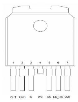
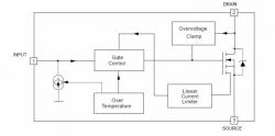
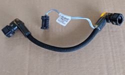
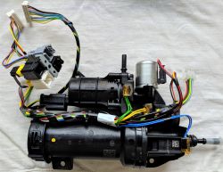
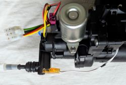
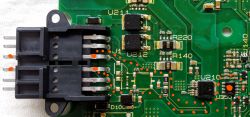
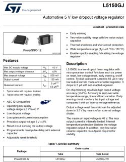
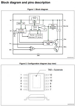
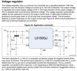
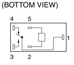
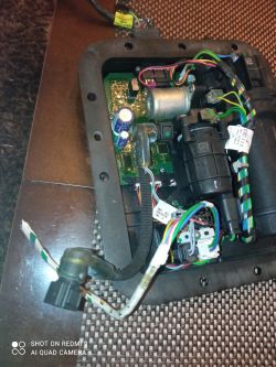
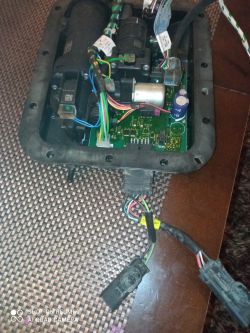
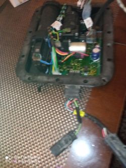
In this topic I will post all the information and pictures related to the repair of the AdBlue tank in the PEUGEOT BOXER III car.
I hope that someone of my colleagues will find this material helpful for a similar repair.
============================================================================================
A very important note before attempting to repair the tank.
The most common error code that comes up when we have a problem with the AdBlue tank is error P20E8 - low urea pressure, which suggests that we have a problem with the pump, or more generally the tank hydraulics. Usually everyone is looking for a pump problem!!! Nothing could be further from the truth. The reason for the error could of course be the pump, but equally any other critical component of the tank. All we need is a faulty one of the temperature sensors, or one of the urea heating circuits or the urea level sensor. The tank control computer tests all tank components every time the engine is started and takes the tank out of service by sending a P20E8 message. Second very important note. If the urea pressure is 4 bar when the service computer is connected, this means that the pressure is probably not there at all!!! The pressure sensor is tuned in such a way that it shows the pressure starting at 4 bar, in the range up to 6 bar! It never shows less than 4 bar. It should be taken for granted that if it reads 4 bar, the system is not working. Usually everyone is convinced that if there is a 4 bar reading, then that 4 bar pressure is there and the pump is not faulty. In my case this was the case, I had a 4 bar reading and when I took the tank apart the pump motor was splashed with urea and completely destroyed, as shown in the photo below in the thread. Please read the whole thread to the end before attempting any repairs. Below is information on how to check each component of the tank. In summary, the error code P20E8 often appears when there is a fault in, for example, the urea temperature sensor or any of the urea heating circuits, and there are as many as 7 of them in the tank!!! Very often a minor problem is the cause of a tank failure and I encourage you to try to repair it. There are even times when the tank is completely operational and the reason for the fault is a faulty heating cable, which is outside the tank but controlled and monitored by the tank. I am referring to the heating cable that heats the urea tube running from the tank to the injector. This is a case that several people have had, one of my colleagues even described his case in this thread. Therefore, it is worth visually checking the tank, wiring, plugs and this tube before removing the tank. It also happens that the plugs and the connections between the tank and the car are corroded and this is the reason for the poor operation of the tank. Finally, one more important note: if an AdBlue-related error occurs, please proceed as soon as possible to repair the tank, do not count on things fixing themselves. Time is of the essence here, because often the reason for the error is a leak in the chamber where the pump is located. The urea splashes onto the plate, which works and fails until the plate is permanently damaged by urea. Corrosion and damage to the components on the board will occur, as well as chewing through the tracks on the board. Just wash and dry all the soggy components in time and you are done.
============================================================================================
As supplement to what I wrote, please read the additional information I posted in this thread in reply #48 of 18 Nov 2022. (#46 18 Nov 2022 13:00)
NOTE VERY IMPORTANT INFORMATION:
I am posting this information here so that Fellows who will attempt to repair the tank will not make a mistake like I did.
After repairing the tank I found the errors I had - text messages on the dashboard:
1) check AdBlue system, see manual
2) check engine
3) 300 km to immobilise engine
4) permanently lit orange engine light
They will disappear by themselves so right away!!! Unfortunately I was wrong, because despite the repaired AdBlue system at my place the messages continued to appear. By clearing all the errors with the service computer, the AdBlue system no longer reports any errors and I have now driven 5,000 km since the repair!!!! Everything is OK. From my observations, it is generally sufficient to repair the fault and the errors disappear immediately, either you have to drive up to 50 km and the car's computer deletes them in the meantime or delete them with the service computer if you don't want to wait. Everything can be done on your own, just a little patience. I have the impression that with the errors it is so that an error appears, the system does not alarm yet, but waits for the next reading, in some time for the next one and only when, let's say, 3 consecutive readings are wrong, a fault message appears and it is the same after the repair - the computer reads the tank status several times and only after several readings everything is back to normal. In my case you have to drive about 50 km in that time.
Update after another month and another 5k km driven.
Everything is great!!! No errors. Gentlemen, do not be afraid of the repair, as long as someone has at least some patience and can unscrew a few screws, it is worth a try. The description posted below is detailed and it is difficult to make a mistake. It's also not a problem to access someone to delete the errors. If anyone is from the vicinity of Krosno (Podkarpackie voivodship), I can give you the contact details of a really good professional who can delete the errors and help you get to grips with the subject from this side!!! There is a large selection of used tanks on Allegro and with a high probability you will be able to make one good one out of "two". I bought a damaged one for £400, which was a parts donor for my tank.
Not all the information I post is 100% certain, so please correct me if anyone has proven knowledge on this subject.
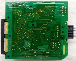
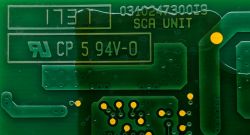
I am looking for service information and a schematic of the electronic board that controls the AdBlue pump.
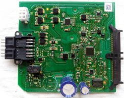
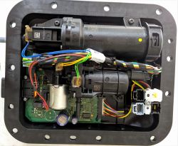
I am also looking for information on the procedure for venting the tank.
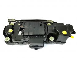
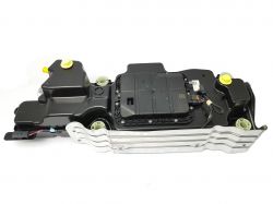
Before repairing the tank, it is worth watching this video:
Removing the tank from the car
==========================
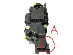
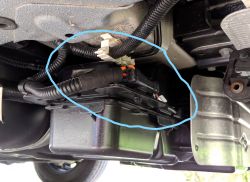
In order to repair the tank it is necessary to remove the tank from the car. Firstly disconnect the battery and disconnect the tank supply block marked A.
See photos below:
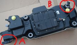
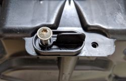
Next, we need to drain the AdBlue fluid from the tank. To do this, unscrew the screw that secures the cap.
Turn the cap to the position shown in the photo below:
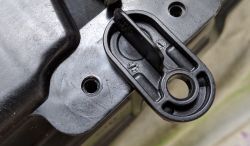
and slide the plug out of the socket with a slight swinging motion.
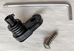
If you want to speed up the flow of fluid, unscrew the blue AdBlue filler cap!!!
Then place something under the tank so that it doesn't drop too much and unscrew the 4 tank fixing screws with a 13 spanner.
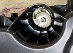
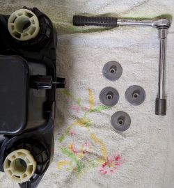
Now disconnect the two tubes, one for the filler and one for the vent (they are next to each other). You don't need any tools for this, the tubes are on quick-release couplings. All you have to do is press with your fingers in the right place and the tube will disengage.
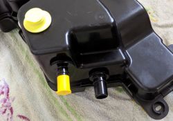
Lower the tank with one side down to have better access to the tube and connector on the other side of the tank. Unplug the tube and connector and remove the tank. The car can be driven, but after a while an AdBlue system failure message will appear and the countdown to the immobilisation of the car will start. We still have the possibility to drive 400 km.
Below is a view of the chassis after removing the tank:
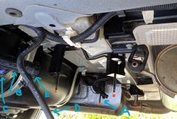
The tank is bolted to the black frame ending in four pins (red dots) with 4 screws.
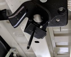
A - quick coupler on the line that feeds pressurised urea to the injector. Next to the cube for the heating circuit supply.
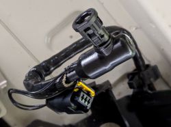
B - urea filler tube ends run upwards to the urea filler
E - quick-connect tube B
C - quick coupling for tank vent pipe
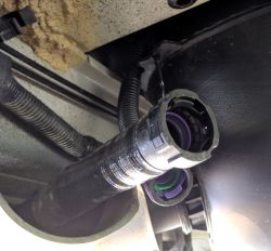
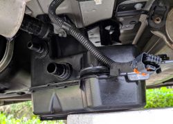
D - tank supply pipe terminated with a plug
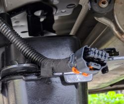
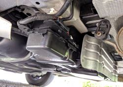
As an addendum to what I have written, please read the additional information I posted in this thread in reply #48 of 18 Nov 2022. (#46 18 Nov 2022 13:00)
Electronic board description:
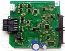
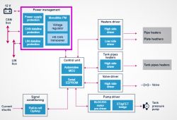
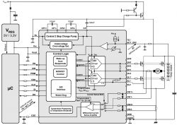
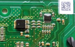
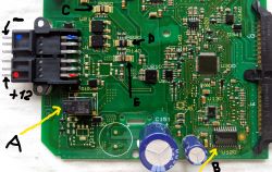
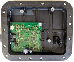
The electronics on the board manages the operation of the tank and sends information on the status of the tank to the car's central computer via the CAN bus (bus). It reads data from two temperature sensors, one pressure sensor and one tank level sensor. It controls one pump, one solenoid valve, seven urea heating circuits.
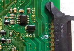
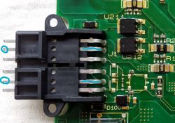
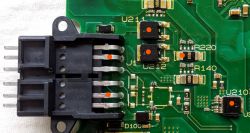
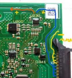
The board has 4 connectors for communication with the above components. See photo of the board (connectors J1 and J2 and two edge connectors J3 and J4)
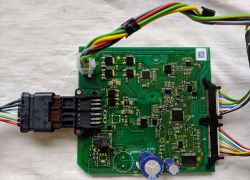
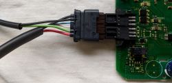
Description of the J1 connector leads in the order shown in the photo from top to bottom:
1 - thick black - tank supply - minus
2 - thinner black - urea tube heating between tank and urea injector (injection) - minus
3 - thin blue CAN bus
4 - thin white CAN bus
5 - green - heating of urea tube between tank and urea injector (injection) - plus
6 - thick red - tank supply +12V
Between the tank The AdBlue pipe (near the fuel tank) and the urea injector (near the engine) run along a urea pipe (see drawing at the bottom of the appendix - item marked 26) which is subject to freezing in winter. At temperatures below -11" C, urea freezes and therefore the entire length of the urea tube is heated by a resistance wire molded into the tube. Leads 2 and 5 of connector J1 supply this resistance wire. This is one of seven urea heating circuits and the only external circuit the other six urea heating circuits are located inside the AdBlue tank.
IMPORTANT NOTE: Tank supply + 12 volt connector J1 (6 - red) appears when the key is turned and supplies power to the tank. The car's central computer waits for a response after CAN from the AdBlue tank. If there is no response then the car computer disconnects the +12V supply to the tank. This could be misinterpreted by the car repairman to mean that the reason for the problems is that there is no +12 supply at connector J1. In summary, if there is no communication between the tank and the car, or the tank is disconnected and removed, then voltage will only appear on J1 connector 6 (+12V) for a few seconds and then disappear.
Description of J2 connector pinout (see photo)
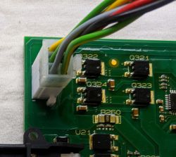
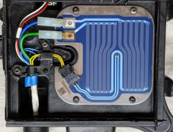
1) Yellow-green pair (100W heater supply) heating the urea in the tank near the filter through which the pump sucks the urea.
The heater is an 8X8 cm plate with a system of resistance paths used to defrost the local urea in the tank in the area of the urea intake by the pump. During a hard frost, the urea in the whole tank (16l) can freeze and this heating plate melts the ice locally in the area of the filter so that the pump can suck in the urea. The heater is located in an unsealed part of the tank and without cutting open the tank you cannot get to it!!!!! As well as the level sensor and the two temperature sensors!!!!
The heater in the form of a plate is the second heating element of seven.
2) The black (minus)-green-yellow (plus) pair of wires feeds the pump motor.
3) The grey-red pair is the heating supply for the tube between the urea dipped filter and the pump (see photo below). This is the third heating element of seven.
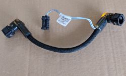
Description of the J3 connector leads in the order shown in the photo from bottom to top. At the bottom is no. 1!!!!!! (see photo)
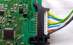
contact no. 1 ( first from the bottom!!!) black ground - control of the solenoid valve.
contact no. 2 red plus - control of solenoid valve.
the next contacts are the power supply for the four remaining of the seven heating circuits:
- white circuit - pair 3 and 7 (white wires)
- blue circuit - pair 4 and 8 (blue wires)
- green circuit - pair 5 and 9 (green wires)
- yellow circuit - pair 6 and 10 (yellow wires)
As you can see from the layout of the tracks, the four aforementioned heating circuits are switched together by the same signal and always work together. If one circuit is short-circuited, the other three will be short-circuited!!!!
The four aforementioned heating circuits (white, blue, green and yellow) heat the 4 urea flow points (see photos below)
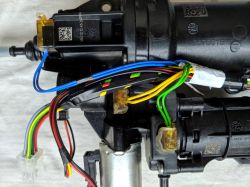
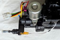
- the white heating circuit heats the urea in the tube (elbow) at the tank outlet.
- green heating circuit heats the urea pump.
- yellow heating circuit heats the area near the solenoid valve and pressure sensor.
- heating circuit the blue one heats the urea accumulator (a small tank with a capacity of a glass in which the urea is pressurised at around 5-6 bar)
Description of the J4 connector leads in the order shown in the photo from bottom to top. At the bottom is no. 1!!!!!! (see photo)
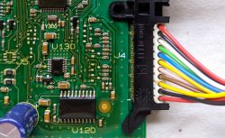
contact no. 1 ( first from the bottom!!!) red supply plus - urea pressure sensor.
contact no. 2 black supply minus - pressure sensor.
contact no. 3 yellow signal (data) from pressure sensor.
The sensor measures the urea pressure fed to the injector (should be around 5-6 bar). The pump pumps the urea into a small tank called an accumulator in which the urea is pressurised at 5-6 bar. In the following I will describe the principle of operation in detail.
--------------------------------------------------------------------------------------------------------------------------------------------------------------
contact no. 4 brown - the temperature sensor is located near the filter and measures the temperature of the urea in the accumulator at the point where the pump takes it.
contact no. 5 light brown - temperature sensor - other end (pair 4 and 5)
Note: The temperature sensor is located at the bottom of the tank and is not accessible!!! You have to cut open the tank to get to it!!!!
---------------------------------------------------------------------------------------------------------------------------------------------------------------
contact #6 yellow - the temperature sensor is located in the central part of the heating plate (described above) and measures the temperature of the heating plate itself. (It measures the temperature of the heating element and not the temperature of the urea like the one described above!!!)
contact no. 7 blue - temperature sensor - other end (pair 6 and 7)
Note: as above - no access to the sensor you have to cut open the tank!!!!
---------------------------------------------------------------------------------------------------------------------------------------------------------------
contact no. 8 signal (data) - level sensor (hall effect sensor cooperates with float in which there is a permanent magnet).
contact no. 9 white - not used!!!
contact no. 10 black power supply for level sensor minus (ground)
contact no. 11 red supply level sensor plus
Note: The level sensor is located next to the heating plate at the bottom of the tank and is not accessible!!! You have to cut open the tank
to get to it!!!!
Below are pictures of the sensors and the heating plate. There is no access to these components!!! You have to cut open the tank and remove part of the housing to make the sensors visible as they are sealed in a plastic box.
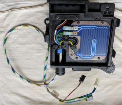
The 100W heating plate and a photo of the temperature sensor placed directly on the heating plate:
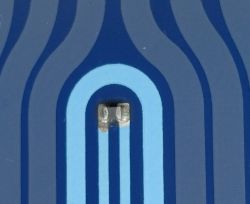
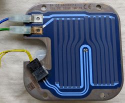
As an addendum to what I have written please read the additional information I posted in this thread in reply #48 of 18 Nov 2022. (#46 18 Lis 2022 13:00)
A temperature sensor that measures the temperature of the fluid (urea) near the filter through which the pump draws urea:
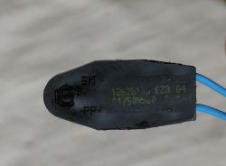
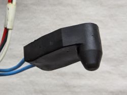
In red is where the urea temperature sensor is located. This is the outside of the sensor box that is in direct contact with the urea. The sensor measures the temperature of the urea through the wall of the box, which is why there is a bulge here for better contact with the fluid.
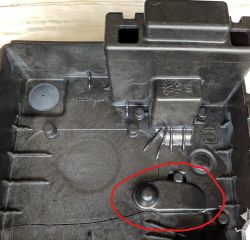
The picture also shows the float chamber of the urea level sensor.
The urea level sensor consists of a chamber in which a float with a permanent magnet is placed (the chamber is in direct contact with the urea and a Hall sensor board which is enclosed in a sealed housing:
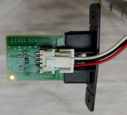
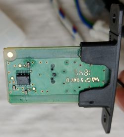
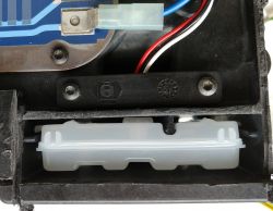
Float with visible permanent magnet inside:
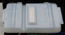
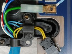
As I wrote earlier the aforementioned sensors cannot be accessed without cutting open the tank. We can only measure the 3 connection cubes at the end of the wiring harness which enters the chamber located at the top of the tank where the electronics and pump are located. The yellow piece is the spigot with which the pump draws AdBlue from the tank, to this spigot on the other side is connected the filter.
See photo:
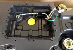
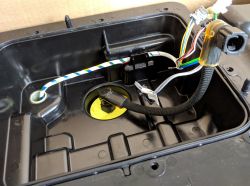
Picture of the harness with 3 cubes:
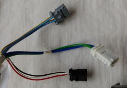
White cube - heating plate power supply
Black cube - fluid level sensor
Grey cube - two temperature sensors ( yellow wires - temperature sensor on the heating plate, blue wires - AdBlue fluid temperature sensor)
TESTING the components that we cannot access without cutting open the tank.
================================================================
We test on the aforementioned white, black and grey cubes
Two slightly thicker wires enter the white cube directly from the urea heating plate.
Plate power 100 W
Power supply 12 V
Measuring with an ohmmeter should indicate about 1.5 Ω in both directions of course. There is no protection along the way etc.
There are two pairs of wires going into the grey cube:
yellow pair from the temperature sensor located in the centre of the heating plate - about 11 kΩ at 25°C.
the blue pair from the urea temperature sensor - 3.3 kΩ at 25°C.
Three wires from the level sensor enter the black cube.
black minus
red plus
white signal
the fluid level sensor is a hall effect sensor. It is made up of several components. We can only test the resistance between the wires. In the conduction direction:
red-white - approx. 900 Ω
red-black - approx. 900 Ω
white-black - approx. 800 Ω
in the direction of resistance, high resistance.
Below in this thread is a detailed description of how to test the level sensor!!!
Photo of the sensor compartment as seen from the top (sensors and heating plate are on the other side):
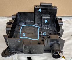
A - chamber in which the float is located.
B - fluid level sensor located on the other side.
C - urea temperature sensor located on the underside.
D - marked place where the heating plate is on the underside.
The chamber is covered by a white plate with a spring. Inside the spring is a filter through which urea is drawn by the pump:
9bb10b73e
Description of the operation of the AdBlue level sensor.
===========================================
The tank has a capacity of about 16 litres which allows you to drive about 6,000 km without refuelling with urea.
The level sensor is placed in the tank about halfway up the tank and the float can move in its chamber about 6 cm up - down. For this reason, the sensor does not read the liquid level in the tank from 0 to 16 litres, but only works within a certain range.
If there are 8 or more litres of urea in the tank, the float is always in the maximum upper position and it is not possible to read exactly how much urea is in the tank (e.g. there may be 8 and there may be 16 litres!!!). In this case, the electronics receive a signal that there is more than 8 litres of urea (how much more? it doesn't know!!!) It only considers that everything is definitely OK. No message appears on the dashboard until the urea level falls below 8 litres!!!
When the urea level drops below 8 litres the float slowly starts to drop and the car is told that there is urea left in the tank for 2400 km this causes the AdBlue light to come on for a moment and a message appears saying that we can drive another 2400 km. As the float goes down further messages appear that we can drive correspondingly fewer kilometres. This continues until the float reaches the lower position, at which point the message appears that we can still drive 600 km. In this case, the AdBlue light is on all the time and a message indicating that the AdBlue must be added every 50 km will appear.
After 600 km, a message appears that the car has been blocked. A minimum of 4 litres of fluid must be added to unblock the car.
As an addendum to what I have written please read the additional information I posted in this thread in reply #48 of 18 Nov 2022. (#46 18 Nov 2022 13:00)
Description of the operation of the hydraulic system located in the tank
================================================
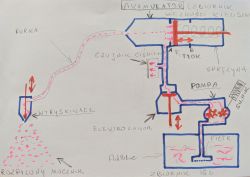
The hydraulic system consists of:
1) a urea filter located in the non-extractable part of the tank.
2) a pump driven by a small DC electric motor.
3) an electro-valve.
4) a pressure sensor.
5) an accumulator of urea (a small container the size of a glass in which the urea is pressurised at about 5-6 bar, one wall of which is a piston on which a precompressed spring exerts pressure). In its construction, the urea accumulator resembles a syringe in which a pre-compressed spring presses on the piston. When the accumulator is charging, the piston moves under the influence of the AdBlue fluid pumped by the pump, overcoming the pressure created by the spring. Thanks to the spring, the urea in the battery remains at a constant pressure of 6 bar. This means that the electric pump does not run continuously, but only briefly to top up the urea in the battery.
The principle of the entire urea dosing system is quite simple. Urea is drawn from the tank by a pump and pumped into the battery. The pump runs until a pressure of around 6 bar is built up in the accumulator. The pressure in the accumulator is controlled by a pressure sensor. To prevent the urea (which is pressurised) from flowing back from the accumulator back into the tank, there is an electro-valve between the accumulator and the pump.
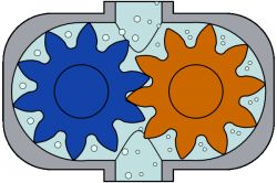
Click on the image.
The gear pump is not a leak-proof pump, by which I mean that when the pump is not pumping, the liquid already pumped to the accumulator can easily squeeze between the gear wheels and return to the tank.
For this reason an electro-valve is necessary, which in this case prevents the urea already pumped into the accumulator from flowing back.
The following operating cycle is performed:
A pressure sensor continuously monitors the pressure in the battery. While the car is being driven, pressurised urea is fed to the urea injector, which injects further portions as necessary, causing the urea pressure in the battery to drop. If the pressure drops to the lower limit, the solenoid valve opens and the pump recharges the battery. Once the battery is charged, the pump stops and the solenoid valve closes. This state continues until the urea pressure in the battery drops again and the cycle repeats.

Photo description:
A+B - battery
part A - round can contains a spring ending in a piston.
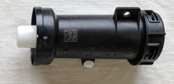
part B - contains a chamber inside with the volume of a glass filled with urea. One wall of the chamber is the piston.
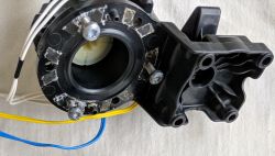
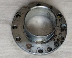
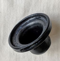
Between parts A and B there is a metal ring connecting the two parts and a rubber cap is placed on the piston which acts as a seal. It prevents urea from entering the spring can. See photos below:
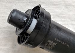
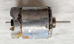
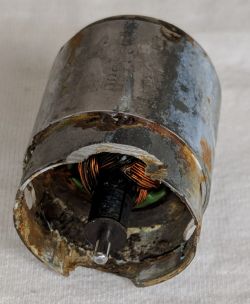
Pictured below is the damaged engine (it was flooded with urea for a long time and corroded):
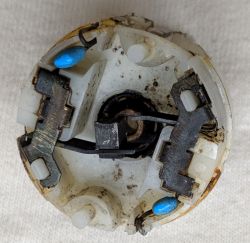
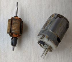
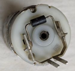

The protection diode shown in the picture is TRANSIL DUAL P6KE
Wikipedia:
Transil (Transient Voltage Suppressor, TVS) is a specialised protection diode that protects sensitive electronic components from the effects of overvoltage, often used to suppress surges and high voltage pulses. It works similarly to a varistor, but is much faster than it. When a threshold voltage is exceeded, it begins to conduct rapidly. The main advantage of the transil is its very short response time - on the order of 1 picosecond. The popular 1.5KE series allows 1500 W of peak power to be knocked out over a short period of time. The transil can be either unidirectional or bidirectional.
Pump:
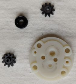
This is a simple gear pump. One pinion is driven by the motor (shown above) and the second pinion is driven directly by the first pinion. See https://pl.wikipedia.org/wiki/Pompa_z%C4%99bata
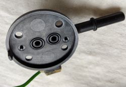
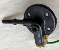
The outer wall of the pump contains the heating element (green circuit). Two holes protected by o-rings can be seen. One sucks urea into the pump and the other forces the urea through the pump gears to the accumulator.
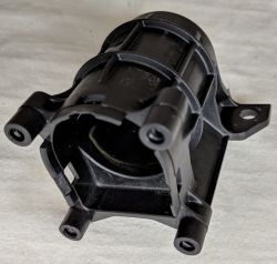
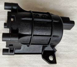
Pump casing in which the motor is housed.
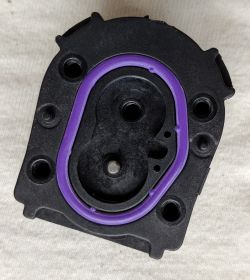
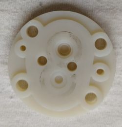
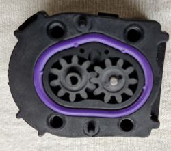
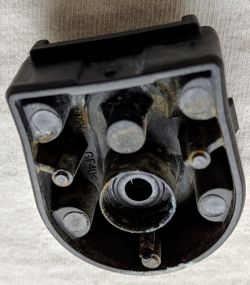


Pump chamber in which the two gears operate. Seal - purple o-ring.
Pressure sensor:
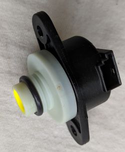
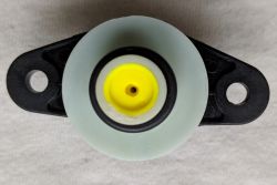
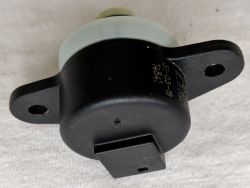
Socket in which the pressure sensor is placed:
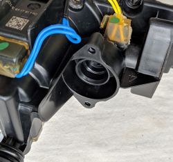
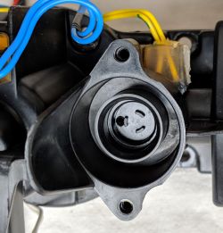
The sensor has a sealing o-ring, is press-fitted into the socket and is secured by two screws.
There is a problem unscrewing these screws because they have unusual heads.
Electrovalve:
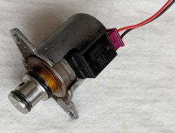
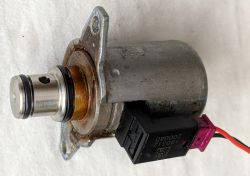
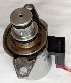
Solenoid valve socket:
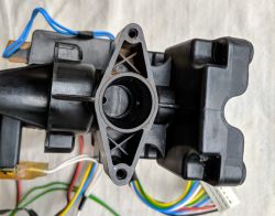
Similar installation to the pressure sensor and the same problem of unscrewing due to unusual screw heads!!!
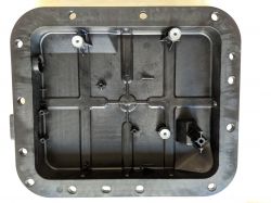
All the above-mentioned components are mounted to a body made of plastic in which there are channels through which the urea flows from the pump to the accumulator. Due to the many hydraulic connections (o-rings and quick-release couplings), urea leakages may occur and cause corrosion. Disassembling the tank is simple and requires no specialist tools. All bolts have torx heads except the four I wrote about earlier. It is necessary to keep the assembly very clean, as there are a lot of seals for the o-rings and even a hair coming up under the o-ring can cause a leak.
Information is contained in the car's manual. It is worth reading.

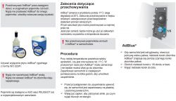
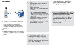
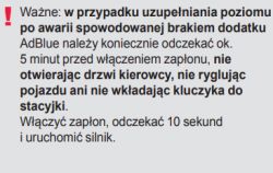
Please read this section of the car manual carefully in particular:
I hope that someone of my colleagues will find this material helpful for a similar repair.
============================================================================================
A very important note before attempting to repair the tank.
The most common error code that comes up when we have a problem with the AdBlue tank is error P20E8 - low urea pressure, which suggests that we have a problem with the pump, or more generally the tank hydraulics. Usually everyone is looking for a pump problem!!! Nothing could be further from the truth. The reason for the error could of course be the pump, but equally any other critical component of the tank. All we need is a faulty one of the temperature sensors, or one of the urea heating circuits or the urea level sensor. The tank control computer tests all tank components every time the engine is started and takes the tank out of service by sending a P20E8 message. Second very important note. If the urea pressure is 4 bar when the service computer is connected, this means that the pressure is probably not there at all!!! The pressure sensor is tuned in such a way that it shows the pressure starting at 4 bar, in the range up to 6 bar! It never shows less than 4 bar. It should be taken for granted that if it reads 4 bar, the system is not working. Usually everyone is convinced that if there is a 4 bar reading, then that 4 bar pressure is there and the pump is not faulty. In my case this was the case, I had a 4 bar reading and when I took the tank apart the pump motor was splashed with urea and completely destroyed, as shown in the photo below in the thread. Please read the whole thread to the end before attempting any repairs. Below is information on how to check each component of the tank. In summary, the error code P20E8 often appears when there is a fault in, for example, the urea temperature sensor or any of the urea heating circuits, and there are as many as 7 of them in the tank!!! Very often a minor problem is the cause of a tank failure and I encourage you to try to repair it. There are even times when the tank is completely operational and the reason for the fault is a faulty heating cable, which is outside the tank but controlled and monitored by the tank. I am referring to the heating cable that heats the urea tube running from the tank to the injector. This is a case that several people have had, one of my colleagues even described his case in this thread. Therefore, it is worth visually checking the tank, wiring, plugs and this tube before removing the tank. It also happens that the plugs and the connections between the tank and the car are corroded and this is the reason for the poor operation of the tank. Finally, one more important note: if an AdBlue-related error occurs, please proceed as soon as possible to repair the tank, do not count on things fixing themselves. Time is of the essence here, because often the reason for the error is a leak in the chamber where the pump is located. The urea splashes onto the plate, which works and fails until the plate is permanently damaged by urea. Corrosion and damage to the components on the board will occur, as well as chewing through the tracks on the board. Just wash and dry all the soggy components in time and you are done.
============================================================================================
As supplement to what I wrote, please read the additional information I posted in this thread in reply #48 of 18 Nov 2022. (#46 18 Nov 2022 13:00)
NOTE VERY IMPORTANT INFORMATION:
I am posting this information here so that Fellows who will attempt to repair the tank will not make a mistake like I did.
After repairing the tank I found the errors I had - text messages on the dashboard:
1) check AdBlue system, see manual
2) check engine
3) 300 km to immobilise engine
4) permanently lit orange engine light
They will disappear by themselves so right away!!! Unfortunately I was wrong, because despite the repaired AdBlue system at my place the messages continued to appear. By clearing all the errors with the service computer, the AdBlue system no longer reports any errors and I have now driven 5,000 km since the repair!!!! Everything is OK. From my observations, it is generally sufficient to repair the fault and the errors disappear immediately, either you have to drive up to 50 km and the car's computer deletes them in the meantime or delete them with the service computer if you don't want to wait. Everything can be done on your own, just a little patience. I have the impression that with the errors it is so that an error appears, the system does not alarm yet, but waits for the next reading, in some time for the next one and only when, let's say, 3 consecutive readings are wrong, a fault message appears and it is the same after the repair - the computer reads the tank status several times and only after several readings everything is back to normal. In my case you have to drive about 50 km in that time.
Update after another month and another 5k km driven.
Everything is great!!! No errors. Gentlemen, do not be afraid of the repair, as long as someone has at least some patience and can unscrew a few screws, it is worth a try. The description posted below is detailed and it is difficult to make a mistake. It's also not a problem to access someone to delete the errors. If anyone is from the vicinity of Krosno (Podkarpackie voivodship), I can give you the contact details of a really good professional who can delete the errors and help you get to grips with the subject from this side!!! There is a large selection of used tanks on Allegro and with a high probability you will be able to make one good one out of "two". I bought a damaged one for £400, which was a parts donor for my tank.
Not all the information I post is 100% certain, so please correct me if anyone has proven knowledge on this subject.
I am looking for service information and a schematic of the electronic board that controls the AdBlue pump.


I am also looking for information on the procedure for venting the tank.


Before repairing the tank, it is worth watching this video:
Removing the tank from the car
==========================
In order to repair the tank it is necessary to remove the tank from the car. Firstly disconnect the battery and disconnect the tank supply block marked A.
See photos below:


Next, we need to drain the AdBlue fluid from the tank. To do this, unscrew the screw that secures the cap.

Turn the cap to the position shown in the photo below:

and slide the plug out of the socket with a slight swinging motion.

If you want to speed up the flow of fluid, unscrew the blue AdBlue filler cap!!!
Then place something under the tank so that it doesn't drop too much and unscrew the 4 tank fixing screws with a 13 spanner.


Now disconnect the two tubes, one for the filler and one for the vent (they are next to each other). You don't need any tools for this, the tubes are on quick-release couplings. All you have to do is press with your fingers in the right place and the tube will disengage.

Lower the tank with one side down to have better access to the tube and connector on the other side of the tank. Unplug the tube and connector and remove the tank. The car can be driven, but after a while an AdBlue system failure message will appear and the countdown to the immobilisation of the car will start. We still have the possibility to drive 400 km.
Below is a view of the chassis after removing the tank:

The tank is bolted to the black frame ending in four pins (red dots) with 4 screws.

A - quick coupler on the line that feeds pressurised urea to the injector. Next to the cube for the heating circuit supply.

B - urea filler tube ends run upwards to the urea filler
E - quick-connect tube B
C - quick coupling for tank vent pipe


D - tank supply pipe terminated with a plug


As an addendum to what I have written, please read the additional information I posted in this thread in reply #48 of 18 Nov 2022. (#46 18 Nov 2022 13:00)
Electronic board description:
The electronics on the board manages the operation of the tank and sends information on the status of the tank to the car's central computer via the CAN bus (bus). It reads data from two temperature sensors, one pressure sensor and one tank level sensor. It controls one pump, one solenoid valve, seven urea heating circuits.
The board has 4 connectors for communication with the above components. See photo of the board (connectors J1 and J2 and two edge connectors J3 and J4)


Description of the J1 connector leads in the order shown in the photo from top to bottom:
1 - thick black - tank supply - minus
2 - thinner black - urea tube heating between tank and urea injector (injection) - minus
3 - thin blue CAN bus
4 - thin white CAN bus
5 - green - heating of urea tube between tank and urea injector (injection) - plus
6 - thick red - tank supply +12V
Between the tank The AdBlue pipe (near the fuel tank) and the urea injector (near the engine) run along a urea pipe (see drawing at the bottom of the appendix - item marked 26) which is subject to freezing in winter. At temperatures below -11" C, urea freezes and therefore the entire length of the urea tube is heated by a resistance wire molded into the tube. Leads 2 and 5 of connector J1 supply this resistance wire. This is one of seven urea heating circuits and the only external circuit the other six urea heating circuits are located inside the AdBlue tank.
IMPORTANT NOTE: Tank supply + 12 volt connector J1 (6 - red) appears when the key is turned and supplies power to the tank. The car's central computer waits for a response after CAN from the AdBlue tank. If there is no response then the car computer disconnects the +12V supply to the tank. This could be misinterpreted by the car repairman to mean that the reason for the problems is that there is no +12 supply at connector J1. In summary, if there is no communication between the tank and the car, or the tank is disconnected and removed, then voltage will only appear on J1 connector 6 (+12V) for a few seconds and then disappear.
Description of J2 connector pinout (see photo)

1) Yellow-green pair (100W heater supply) heating the urea in the tank near the filter through which the pump sucks the urea.
The heater is an 8X8 cm plate with a system of resistance paths used to defrost the local urea in the tank in the area of the urea intake by the pump. During a hard frost, the urea in the whole tank (16l) can freeze and this heating plate melts the ice locally in the area of the filter so that the pump can suck in the urea. The heater is located in an unsealed part of the tank and without cutting open the tank you cannot get to it!!!!! As well as the level sensor and the two temperature sensors!!!!
The heater in the form of a plate is the second heating element of seven.
2) The black (minus)-green-yellow (plus) pair of wires feeds the pump motor.
3) The grey-red pair is the heating supply for the tube between the urea dipped filter and the pump (see photo below). This is the third heating element of seven.

Description of the J3 connector leads in the order shown in the photo from bottom to top. At the bottom is no. 1!!!!!! (see photo)

contact no. 1 ( first from the bottom!!!) black ground - control of the solenoid valve.
contact no. 2 red plus - control of solenoid valve.
the next contacts are the power supply for the four remaining of the seven heating circuits:
- white circuit - pair 3 and 7 (white wires)
- blue circuit - pair 4 and 8 (blue wires)
- green circuit - pair 5 and 9 (green wires)
- yellow circuit - pair 6 and 10 (yellow wires)
As you can see from the layout of the tracks, the four aforementioned heating circuits are switched together by the same signal and always work together. If one circuit is short-circuited, the other three will be short-circuited!!!!
The four aforementioned heating circuits (white, blue, green and yellow) heat the 4 urea flow points (see photos below)


- the white heating circuit heats the urea in the tube (elbow) at the tank outlet.
- green heating circuit heats the urea pump.
- yellow heating circuit heats the area near the solenoid valve and pressure sensor.
- heating circuit the blue one heats the urea accumulator (a small tank with a capacity of a glass in which the urea is pressurised at around 5-6 bar)
Description of the J4 connector leads in the order shown in the photo from bottom to top. At the bottom is no. 1!!!!!! (see photo)

contact no. 1 ( first from the bottom!!!) red supply plus - urea pressure sensor.
contact no. 2 black supply minus - pressure sensor.
contact no. 3 yellow signal (data) from pressure sensor.
The sensor measures the urea pressure fed to the injector (should be around 5-6 bar). The pump pumps the urea into a small tank called an accumulator in which the urea is pressurised at 5-6 bar. In the following I will describe the principle of operation in detail.
--------------------------------------------------------------------------------------------------------------------------------------------------------------
contact no. 4 brown - the temperature sensor is located near the filter and measures the temperature of the urea in the accumulator at the point where the pump takes it.
contact no. 5 light brown - temperature sensor - other end (pair 4 and 5)
Note: The temperature sensor is located at the bottom of the tank and is not accessible!!! You have to cut open the tank to get to it!!!!
---------------------------------------------------------------------------------------------------------------------------------------------------------------
contact #6 yellow - the temperature sensor is located in the central part of the heating plate (described above) and measures the temperature of the heating plate itself. (It measures the temperature of the heating element and not the temperature of the urea like the one described above!!!)
contact no. 7 blue - temperature sensor - other end (pair 6 and 7)
Note: as above - no access to the sensor you have to cut open the tank!!!!
---------------------------------------------------------------------------------------------------------------------------------------------------------------
contact no. 8 signal (data) - level sensor (hall effect sensor cooperates with float in which there is a permanent magnet).
contact no. 9 white - not used!!!
contact no. 10 black power supply for level sensor minus (ground)
contact no. 11 red supply level sensor plus
Note: The level sensor is located next to the heating plate at the bottom of the tank and is not accessible!!! You have to cut open the tank
to get to it!!!!
Below are pictures of the sensors and the heating plate. There is no access to these components!!! You have to cut open the tank and remove part of the housing to make the sensors visible as they are sealed in a plastic box.

The 100W heating plate and a photo of the temperature sensor placed directly on the heating plate:


As an addendum to what I have written please read the additional information I posted in this thread in reply #48 of 18 Nov 2022. (#46 18 Lis 2022 13:00)
A temperature sensor that measures the temperature of the fluid (urea) near the filter through which the pump draws urea:


In red is where the urea temperature sensor is located. This is the outside of the sensor box that is in direct contact with the urea. The sensor measures the temperature of the urea through the wall of the box, which is why there is a bulge here for better contact with the fluid.

The picture also shows the float chamber of the urea level sensor.
The urea level sensor consists of a chamber in which a float with a permanent magnet is placed (the chamber is in direct contact with the urea and a Hall sensor board which is enclosed in a sealed housing:


Float with visible permanent magnet inside:

As I wrote earlier the aforementioned sensors cannot be accessed without cutting open the tank. We can only measure the 3 connection cubes at the end of the wiring harness which enters the chamber located at the top of the tank where the electronics and pump are located. The yellow piece is the spigot with which the pump draws AdBlue from the tank, to this spigot on the other side is connected the filter.
See photo:


Picture of the harness with 3 cubes:

White cube - heating plate power supply
Black cube - fluid level sensor
Grey cube - two temperature sensors ( yellow wires - temperature sensor on the heating plate, blue wires - AdBlue fluid temperature sensor)
TESTING the components that we cannot access without cutting open the tank.
================================================================
We test on the aforementioned white, black and grey cubes
Two slightly thicker wires enter the white cube directly from the urea heating plate.
Plate power 100 W
Power supply 12 V
Measuring with an ohmmeter should indicate about 1.5 Ω in both directions of course. There is no protection along the way etc.
There are two pairs of wires going into the grey cube:
yellow pair from the temperature sensor located in the centre of the heating plate - about 11 kΩ at 25°C.
the blue pair from the urea temperature sensor - 3.3 kΩ at 25°C.
Three wires from the level sensor enter the black cube.
black minus
red plus
white signal
the fluid level sensor is a hall effect sensor. It is made up of several components. We can only test the resistance between the wires. In the conduction direction:
red-white - approx. 900 Ω
red-black - approx. 900 Ω
white-black - approx. 800 Ω
in the direction of resistance, high resistance.
Below in this thread is a detailed description of how to test the level sensor!!!
Photo of the sensor compartment as seen from the top (sensors and heating plate are on the other side):

A - chamber in which the float is located.
B - fluid level sensor located on the other side.
C - urea temperature sensor located on the underside.
D - marked place where the heating plate is on the underside.
The chamber is covered by a white plate with a spring. Inside the spring is a filter through which urea is drawn by the pump:
9bb10b73e
Description of the operation of the AdBlue level sensor.
===========================================
The tank has a capacity of about 16 litres which allows you to drive about 6,000 km without refuelling with urea.
The level sensor is placed in the tank about halfway up the tank and the float can move in its chamber about 6 cm up - down. For this reason, the sensor does not read the liquid level in the tank from 0 to 16 litres, but only works within a certain range.
If there are 8 or more litres of urea in the tank, the float is always in the maximum upper position and it is not possible to read exactly how much urea is in the tank (e.g. there may be 8 and there may be 16 litres!!!). In this case, the electronics receive a signal that there is more than 8 litres of urea (how much more? it doesn't know!!!) It only considers that everything is definitely OK. No message appears on the dashboard until the urea level falls below 8 litres!!!
When the urea level drops below 8 litres the float slowly starts to drop and the car is told that there is urea left in the tank for 2400 km this causes the AdBlue light to come on for a moment and a message appears saying that we can drive another 2400 km. As the float goes down further messages appear that we can drive correspondingly fewer kilometres. This continues until the float reaches the lower position, at which point the message appears that we can still drive 600 km. In this case, the AdBlue light is on all the time and a message indicating that the AdBlue must be added every 50 km will appear.
After 600 km, a message appears that the car has been blocked. A minimum of 4 litres of fluid must be added to unblock the car.
As an addendum to what I have written please read the additional information I posted in this thread in reply #48 of 18 Nov 2022. (#46 18 Nov 2022 13:00)
Description of the operation of the hydraulic system located in the tank
================================================

The hydraulic system consists of:
1) a urea filter located in the non-extractable part of the tank.
2) a pump driven by a small DC electric motor.
3) an electro-valve.
4) a pressure sensor.
5) an accumulator of urea (a small container the size of a glass in which the urea is pressurised at about 5-6 bar, one wall of which is a piston on which a precompressed spring exerts pressure). In its construction, the urea accumulator resembles a syringe in which a pre-compressed spring presses on the piston. When the accumulator is charging, the piston moves under the influence of the AdBlue fluid pumped by the pump, overcoming the pressure created by the spring. Thanks to the spring, the urea in the battery remains at a constant pressure of 6 bar. This means that the electric pump does not run continuously, but only briefly to top up the urea in the battery.
The principle of the entire urea dosing system is quite simple. Urea is drawn from the tank by a pump and pumped into the battery. The pump runs until a pressure of around 6 bar is built up in the accumulator. The pressure in the accumulator is controlled by a pressure sensor. To prevent the urea (which is pressurised) from flowing back from the accumulator back into the tank, there is an electro-valve between the accumulator and the pump.

Click on the image.
The gear pump is not a leak-proof pump, by which I mean that when the pump is not pumping, the liquid already pumped to the accumulator can easily squeeze between the gear wheels and return to the tank.
For this reason an electro-valve is necessary, which in this case prevents the urea already pumped into the accumulator from flowing back.
The following operating cycle is performed:
A pressure sensor continuously monitors the pressure in the battery. While the car is being driven, pressurised urea is fed to the urea injector, which injects further portions as necessary, causing the urea pressure in the battery to drop. If the pressure drops to the lower limit, the solenoid valve opens and the pump recharges the battery. Once the battery is charged, the pump stops and the solenoid valve closes. This state continues until the urea pressure in the battery drops again and the cycle repeats.

Photo description:
A+B - battery
part A - round can contains a spring ending in a piston.

part B - contains a chamber inside with the volume of a glass filled with urea. One wall of the chamber is the piston.

Between parts A and B there is a metal ring connecting the two parts and a rubber cap is placed on the piston which acts as a seal. It prevents urea from entering the spring can. See photos below:


Pictured below is the damaged engine (it was flooded with urea for a long time and corroded):


The protection diode shown in the picture is TRANSIL DUAL P6KE
Wikipedia:
Transil (Transient Voltage Suppressor, TVS) is a specialised protection diode that protects sensitive electronic components from the effects of overvoltage, often used to suppress surges and high voltage pulses. It works similarly to a varistor, but is much faster than it. When a threshold voltage is exceeded, it begins to conduct rapidly. The main advantage of the transil is its very short response time - on the order of 1 picosecond. The popular 1.5KE series allows 1500 W of peak power to be knocked out over a short period of time. The transil can be either unidirectional or bidirectional.
Pump:
This is a simple gear pump. One pinion is driven by the motor (shown above) and the second pinion is driven directly by the first pinion. See https://pl.wikipedia.org/wiki/Pompa_z%C4%99bata


The outer wall of the pump contains the heating element (green circuit). Two holes protected by o-rings can be seen. One sucks urea into the pump and the other forces the urea through the pump gears to the accumulator.


Pump casing in which the motor is housed.


Pump chamber in which the two gears operate. Seal - purple o-ring.
Pressure sensor:


Socket in which the pressure sensor is placed:


The sensor has a sealing o-ring, is press-fitted into the socket and is secured by two screws.
There is a problem unscrewing these screws because they have unusual heads.
Electrovalve:


Solenoid valve socket:

Similar installation to the pressure sensor and the same problem of unscrewing due to unusual screw heads!!!
All the above-mentioned components are mounted to a body made of plastic in which there are channels through which the urea flows from the pump to the accumulator. Due to the many hydraulic connections (o-rings and quick-release couplings), urea leakages may occur and cause corrosion. Disassembling the tank is simple and requires no specialist tools. All bolts have torx heads except the four I wrote about earlier. It is necessary to keep the assembly very clean, as there are a lot of seals for the o-rings and even a hair coming up under the o-ring can cause a leak.
Information is contained in the car's manual. It is worth reading.


Please read this section of the car manual carefully in particular:


