logo elektroda
logo elektroda
X
logo elektroda

PEUGEOT BOXER III - Repair of the AdBlue tank PEUGEOT BOXER III, CITROEN JUMPER

mako122 153435 224
ADVERTISEMENT
Treść została przetłumaczona polish » english Zobacz oryginalną wersję tematu
  • #181 21140452
    szustakowski
    Level 2  
    >>21140408 .

    And can someone explain to me what this flashing of the electronics does?
    What changes does it make?

    I ask because I wouldn't want to return the tank for reconditioning and someone will "fix" it. In a year's time there is supposed to be mandatory emissions measurement at every diagnostic station, the penalty for being found to have "removed" the ecology is £12000. Apparently the probes will be able to measure both DPF and adBlue.
  • ADVERTISEMENT
  • #184 21143831
    ShadowSAF
    Level 4  
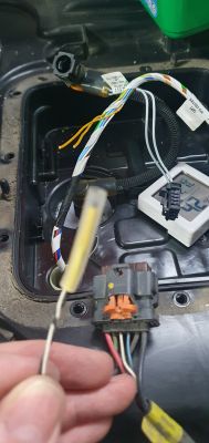
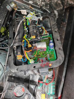
    I have the problem, that the car doesn't has any connection to the tank. So: i opened the tank and measured: before i plug the plug in, i have between black and red 12-14V, and the canbus each 2,5V. As soon as i plug in and measure, it says 0V between black and red and 2,5V at the canbus (directly after start of the car). how can this be? Close-up of the interior of a car tank with electronics and wires.

    Added after 37 [minutes]:

    >>21143831

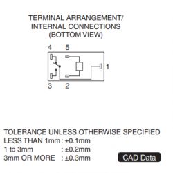
    i measured the relays next to the plug: Terminal connection diagram for a relay.

    Between 1 and 3 i have 20kOhm, and 1 and 4 0kOhm - if i apply a voltage to it, i hear it clicking, but shouldn't the resistance between 1 and 3 (or 4) be much more than 20kOhm?

    Nachtrag: I measured the relays - its broken - i will get a new one.
  • ADVERTISEMENT
  • #185 21145213
    mako122
    Level 12  
    >>21143831 .


    This is described in this thread. When you start the engine, an AdBlue tank test is done for about 30s if the engine computer does not get a positive response after CAN the supply to the tank is cut off. What errors do you have?

    This description of the problem is at the beginning of this thread:

    IMPORTANT NOTE: tank supply + 12 volt connector J1 (6 - red) appears when the key is turned and supplies the tank. The car's central computer waits for a response after CAN from the AdBlue tank. If there is no response then the car's computer disconnects the +12V supply to the tank. This could be misinterpreted by the car repairman to mean that the reason for the problems is that there is no +12 supply at connector J1. In summary, if there is no communication between the tank and the car, or the tank is disconnected and removed, then voltage will only appear on J1 connector 6 (+12V) for a few seconds and then disappear.


    Or maybe you have a short between black and red? Measure the board with an ohmmeter.
    The board is not splashed? There was no moisture when you opened it?
  • #186 21146264
    ShadowSAF
    Level 4  
    >>21145213>>21145213

    Thanks for the reply! So first i had a loose contact, which explained the 0V -> the power stays and doesn't turn off, but the CANBus has now instead of 2.5V more than 4.5V on both lines.

    The board looks good and is not splashed - there was not any moisture.

    I measured the resistance between black and red on the board and it is 12kOhm -> what should be a normal value?
  • ADVERTISEMENT
  • #187 21154823
    ShadowSAF
    Level 4  
    End of the story - I ordered a new original tank and now it works.. the board of the tank probably was damaged and not easily fixable..
  • #188 21174016
    zenq
    Level 12  
    mako122 wrote:
    There are 7 urea heating circuits in the AdBlue system:

    I include the correct resistance values of all circuits here before describing them in detail:

    A) urea heating plate in the tank (there is no direct access to it) - 1.3 Ω
    B) wire connecting the urea filter to the pump assembly (about 30 cm long) - 27.0 Ω
    C) "green" circuit heating the pump - 55.0 Ω
    D) "yellow" circuit heating the solenoid valve - 55.0 Ω
    E) "blue" circuit urea accumulator heating - 212.0 Ω
    F) "white" circuit heating the elbow where the urea exits the tank - 22.0 Ω
    G) circuit heating the tube between the tank and the injector (about 1.5 m) - 2.5 Ω


    Should it really be above 200 ohms on the "blue"? i only have 12.5... the heater in the pump has a short circuit?
  • #189 21174112
    mako122
    Level 12  
    >>21174016 .

    I'll try to check it out soon and let you know.

    Yes, you're right it was supposed to be 20 Ω not 200 Ω. I will rectify this immediately.

    These heaters have quite a large range of parameters. I have two pumps, I checked now on one I have 19.6 Ω and on the other 15.8 Ω.
  • #190 21175223
    zenq
    Level 12  
    ok thanks, so that's not it.
    Six months ago I did the sensor on the heater, now it's not going again :/.
  • #191 21217688
    mklimaszm
    Level 1  
    Hello.
    Nice work on the topic, keep it up, great job.

    Patient c4 b7 bluehdi 100 2015. Standard pressure fault. All sensors and circuits in the tank working. The problem is with the tube between the tank and the injector. When measuring the resistance of the tube I have 0 Ohm. The tube consists of 2 parts connected together behind the engine. The first section of about 2.5m, the resistance measured at the pins at both ends of the cable is 1 Ohm. The second section of about a metre has no transition between the connector and the cube at the injector. I can see that the urea tube goes straight to the injector, while the cable goes into a thicker cable harness and goes somewhere near the relays, from there it only returns to the injector.
    I don't really know where to look for the problem next. Maybe someone has already dealt with a similar problem?

    Edit.
    Problem solved. A break in the cables 20 cm behind the cubes connecting the two sections. You can't see where, but when moving the resistance appears. Final shorter section of cable to be replaced.
  • #192 21241114
    Marr991
    Level 2  
    Hello,
    super worked out topic. In the services in Lodz the only knowledge they have on the subject in ASO, replacing the tank with a new one (they have already replaced one under warranty) as there is a low pressure error, in other services removing the adblue from the controller.
    I had a low urea pressure error a year and a half ago. I took the tank apart, measured everything as the author described, everything was fine, put it together, poured adblue and so far 0 errors. I think the problem was adblue crystals (the problem occurred after the winter period) which blocked the system, I have since topped up with Tunap.

    The problem reappeared about a month ago, but in a different form. I use the car on a regular route (home-market-store-home), 3 times a week. Driving from home to the market (engine is cold) after driving 2 km the check appears (check adblue system), it lights up all the time after reaching the market (about 15 km), at the market the engine runs for about 40 min at idle, it is started several times. Returning from the market after driving 2 km the check goes off and does not appear again that day. Back home, I connect the computer, read error P20E8, run a diagbox pressure test, which is successful (read system pressure ~5,900). I clear the error, however the pattern during the next drive repeats itself. I have also performed other tests in the diagbox, venting - venting too fast, urea line heating - system failure, tank heating - system failure, injector heating - operating conditions not achieved, please repeat or contact the help centre.
    I don't know where best to start the diagnosis, as the error only appears on a cold engine. It seemed to me that the problem might be with the battery, I replaced it with a new one, however this did not help. A year and a half ago the check wouldn't go away and the system pressure test failed. Now it is different. It seems to me that the bleeding and heating tests 1.5 years ago ended similarly to now, but during all this time the check did not appear, the adblue was wearing off, as I had to top up twice during this time. Since the problem appeared I have used the car about 12 times, 3 times the light did not appear at all, 1 time it appeared and did not disappear until I arrived home, in addition the message "check engine" appeared, in the other cases I had to deal with the above described pattern.

    Edit:
    I took the tank apart, resistance on the yellow wires from the temperature sensor on the board 290 Ω, resistance on the wires from the urea level red-white 1.5MΩ, red-black 0.58MΩ, white-black 5.40MΩ. Other values correct. I will look for a used tank for a swap or buy a new one. What could be the cause of the check disappearing?
  • #193 21253540
    marcindaczynski
    Level 2  
    Hey, I couldn't find an answer anywhere until I finally got to this topic. Maybe someone here can give a hint.

    The patient is not a Peugeot or Citroen, but a 2019 OPEL Astra K 1.6 CDTI. From what I've been able to read in this topic, the principle of AdBlue is almost the same everywhere.

    Last week the car was returned for an oil and filter change. At handover, the AdBlue range showed about 1600 km - 16%.

    After receiving the car and driving about 30 km, a message popped up about the necessary AdBlue service and locking the car for 900. The computer shows two faults - P221C low current of the heater 2 of the reducer solution tank and P2BAD high concentration of exhaust oxides of nitrogen.

    Could the occurrence of this fault be related to the lack of AdBlue top-up?

    I managed to read in this topic that it is possible to fool the computer by soldering resistors into a particular circuit. (Although a temporary solution). If so, which one specifically?

    Does replacing the heater involve replacing the whole tank?
  • #194 21269126
    earlsgate
    Level 2  
    ref to post here : 182 (03/07/24). seems like that Peugeot Technical Service Bulletin B1KW017XQ0 (24/06/2024) mentions a possible and economical repair of the heating thermistor by a French company who can provide a 2 year warranty on their work. The TSB details a simple yellow wire resistance test to establish if a repair is viable. Could be a DIY solution in the right hands too, but not that sure one could easily access that part of the tank to presumably replace that thermistor?

    my first here, so thanks especially to its creator, and the informed level of discussion from others. I also note there are some interesting discussions from Spanish contributors both on Youtube and their "guiapsa" forum
  • #195 21345885
    C5_508
    Level 1  
    Guys, can anyone suggest if the heating element in the tank is made of magnetic material? I want to place a thermistor (glued to the magnet) in the cavity instead of the original temperature sensor
  • #196 21360802
    mako122
    Level 12  
    >>21345885 .

    Yes, this is a board made of copper. You have a photo and description of this plate in this thread.
  • #197 21360838
    earlsgate
    Level 2  
    interesting discussion thread in the "frenchcarforum" which outlines a repair of the adblue pump sensor, includes a full list of parts needed for the repair. Should easily translate

    https://frenchcarforum.co.uk/forum/viewtopic.php?t=81429

    did not notice a repair made like this here, only reference to the part number for importation, which seems costly and time consuming
  • ADVERTISEMENT
  • #198 21376145
    PIMP_MY_RIDE-P1
    Level 11  
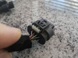
    Close-up of a car electrical plug with multiple colored wires. .
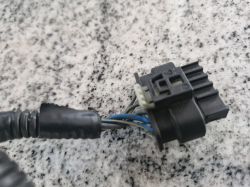
    Photo of an electrical connector with a wiring harness. .
    Close-up of an electrical harness with a black connector, visible wires in blue and gray insulation. .
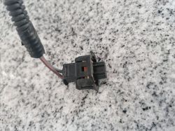
    Close-up of a car electrical connector with wires on a countertop surface. .
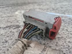
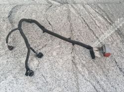
    Wiring harness for the AdBlue system from a Fiat Ducato 2.3JTD 160HP 2019 on a granite surface. .


    Hi! In the photo above is my adblue harness from a 2019 ducato 2.3jtd 160hp

    I need information on which plug it is from the urea level sensor - as the post describes a cube with three wires and I have different ones
  • #199 21376825
    Reflekt
    Level 17  
    The urea level sensor cube comes out of the tank under the controller housing.
  • #200 21400608
    Pablo_Pablo
    Level 3  
    Hey,
    Firstly, thanks to the author of the topic for the huge amount of work put in to work out the whole thing like this.
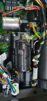
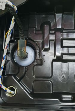
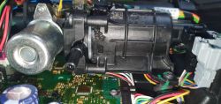
    I have a problem with ADBLUE in a 2017 C4B7. It started with the message "system fault, starting impossible in 1100 km". I refilled the fluid, the UREA and SERVICE lights disappeared for a while, but after a few kilometres the problem returned. On top of that, the check light came on. Pressure error on the comp, of course. Added fluid top-up, errors cleared and of course it all came back after a few kilometres. So I started by charging the battery and inspecting the whole system. No mechanical faults - everything looks like new. After pulling out the tank and unscrewing the housing, you can clearly see a leak at the pump - I'm uploading photos.
    View of the interior of a car's AdBlue system with a pump. .
    Image of the vehicle's container interior with leaking fluid near the pump. .
    Close-up of AdBlue pump with visible leakage and car electronics. .

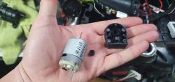
    After disassembling the pump I presume the culprit is the simmering on the motor shaft - fortunately I took everything apart quickly and the motor is like new.
    Has anyone managed to get hold of such a simmering? The smallest I've been able to find is 3 or 4mm and here the shaft is 2.3mm.
    Motor and housing of AdBlue pump on a hand. .
    Unfortunately buying a used pump is a high probability of the same problem.
    In addition, after measurements I found a defective SMD thermistor - the yellow circuit in the grey cube - measuring only 0.37 kΩ at 14 °C. The rest of the circuits after checking seem to give correct values. The only thing left to do is to check the fluid level circuit, but should it turn out to be broken, I will use a divider.
    And here is my question - what power resistors did you use for the divider?
    Thanks in advance for your help.
  • #201 21400694
    mako122
    Level 12  
    Pablo_Pablo wrote:
    what power resistors did you use for the divider?


    Any, there is very little current flowing there. They can be for example 0,25W as for this simmering someone had a way to do it. I'll try to look for it soon and provide info. I sent a private message.
  • #202 21418636
    krisf6
    Level 10  
    C4 GP 2.0 BlueHDI. Adblue error no communication with can bus U029D 87 and P2BAD00. Tank removed, electronics and rest as new, pump working, other components checked. I still have a board to swap but does that make sense?
  • #203 21418720
    mako122
    Level 12  
    >>21418636 .
    Please check the plug that goes to the tank. The two thicker wires are the power supply and the two thin ones so twisted are the CAN. Maybe there is no contact in the plug or it is corroded. If there is, check the part of the board that is responsible for CAN communication. There is a description in this thread which part of the board it is. It makes sense to replace it because the other board may have this part in working order. Please look for damage under a magnifying glass. It is necessary to check whether the tank is supplied with 12V because if not, communication will not work because the board must be powered for CAN to work.
  • #204 21418750
    krisf6
    Level 10  
    Plug checked, power supply is there. The harness between the plugs also has passages, generally everything looks like new, no signs of corrosion, oxidation, etc. I have the same board only from another vehicle, dismantled as working.

    Added after 20 [minutes]: .

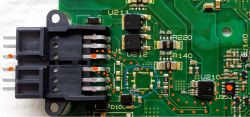
    Close-up of a green printed circuit board with various electronic components, including a connector and a marked area. .
    There is some circuit soldered in the marked area on my board, on the board I want to substitute there is not.
    On both boards the resistance of the can circuit is the same 126 ohms. Conclusion, there is no fault?
  • #205 21418875
    mako122
    Level 12  
    >>21418750 .

    If the Lord had the opportunity to check with an oscilloscope if any data is flying over this CAN. Maybe there is a problem with the harness somewhere further down. A board from another car is unlikely to fit because it won't get along with the engine computer. I mean a different type of vehicle e.g. one is a C4 and the other a C3 because they have different software often different AdBlue tank capacity etc.
  • #206 21418887
    krisf6
    Level 10  
    Where under the bonnet does this harness go? I could check for a break.
  • #207 21419452
    mako122
    Level 12  
    >>21418887 .
    I don't know how it is in your car because I don't know this model. Often the signal goes directly to the ECU (Electronic Control Unit), which is the central control computer.
    You may find information here: https://dailydriven.ro/pl/jak-dowiedziec-sie-gdzie-znajduje-sie-ecu-w-citroen-c4

    But I would not stick strictly to this message, but check the tank, heaters, etc. Look at the electronics under a magnifying glass etc. Often these errors do not indicate what is really faulty. Please read this thread carefully. The car, after starting, tests the tank for about 30 s and if it does not get a positive answer that it is OK then after this time it stops supplying power to the tank (cuts off power completely with a relay) then after this time there is no more communication with the tank because there is no power and it is no wonder that you can get a com that there is no data over CAN from the tank. As the car has not been in an accident etc it is unlikely that there is a faulty harness. I definitely think that it is not a problem with the communication over CAN rather somewhere else you have to look for the cause.
  • #208 21426633
    Pablo_Pablo
    Level 3  
    Hey,
    I'm posting an update because I promised the topic founder, and he deserves credit for his immense work.
    After about 2 weeks of using the car, I consider the repair successful :) . In my case, the repair consisted of replacing the thermistor and sealing the pump. All other components proved to be in working order. I bought a regular 10kohm thermistor. After cutting the circuit from the tank, I soldered a new one, put a piece of silicone tubing over it and inserted it through the hole where the wiring harness goes - as far as possible.
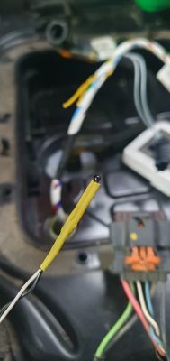
    Close-up of electrical wires with attached thermistor. .
    Car wiring repair with visible thermistor and electrical connectors. .
    I sealed the pump by replacing all the o-rings with new ones. I replaced the two smaller ones with a different size from the originals, according to the information from the author of the post - and here again a big thank you for your help and interest!
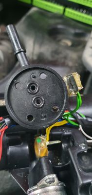
    Close-up of car pump components with visible wires and O-rings. .
    The new o-rings are 5.5 x 1.5 - 70NBR - they are thicker and it is noticeable - they sit tight and when assembling you have to gently tighten each screw diagonally so that the plastic part doesn't break from the stress - the difference is really quite substantial.
    I fitted a larger o-ring with 22x2 silicone - 70 VMQ.
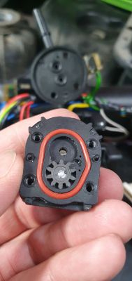
    View of repaired mechanical part with a gasket. .
    And now the most interesting thing about this leaking pump - the main culprit for the fluid leak into the motor housing is the simmering on the shaft, which is unusual and cannot be bought anywhere.
    7bbc2a748 .
    It is embedded in such a "socket"
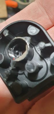
    View of the inner part of a plastic casing with a spot for an O-ring .
    It just rests on the circumference on the spline visible in the centre. So I figured it out like this:
    I purchased 2 tiny 2x2 o-rings that fit perfectly in the centre of the spline, but fit snugly over the motor shaft - it has a diameter of 2.3mm. The height of the spline is 2.5mm and the 2 o-rings on top of each other give us 4mm, so that the simmering ring protrudes slightly when inserted into the socket.
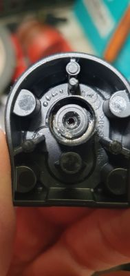
    Interior view of a pump with an installed seal. .
    As the housing at the rear has a rubber drag that presses the motor inside us, putting everything together "crimps" the tapered inner part of the simmering in the protruding o-ring, giving us a tight seal on the shaft.
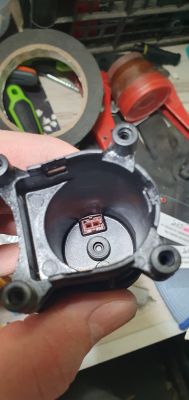
    Interior of a car pump part with a visible seal mounting spot. .
    Once assembled, by turning the pinion on the motor shaft you can feel a marginally higher resistance but completely non-threatening to the engine.
    After putting everything together, I cleared the errors using the app from my phone and so far they have not reappeared.
    Best regards and thanks again to the author of the topic!!!
  • #209 21461118
    baldy77
    Level 1  
    Hi all,

    I had to register to say thank you! With the help of this forum I repaired my Adblue tank. Problem was with the urea heating plate, NTC had a resistance of about 400 ohms. So I added a 10Kohm resistor in series with the "yellow-yellow" wire and now the check engine light and urea light are turned off. Diagbox says there are no faults anymore, yippee!!

    I encourage everyone with Adblue problems to try repairing, it is not difficult.

    Thank you so much mako122 for starting this Adblue repair-thread!
  • #210 21484538
    mlody300
    Level 12  
    >>21461118 I also had the same thing, these thermistors are faulty and there is no access to them, I used a second thermistor inserted into the tank along the cables .I know that this will not measure the exact temperature of the heater but there will be reactions to temperature changes. I would not risk including a resistor in series, this defective thermistor may completely lose conduction, any change in resistance and the tank will be removed again. It is better to disconnect it completely and put a resistor in its place.

Topic summary

The discussion revolves around the repair and troubleshooting of the AdBlue tank in PEUGEOT BOXER III and CITROEN JUMPER vehicles. Users share their experiences with common issues such as low pressure errors (P20E8), sensor malfunctions, and the need for system resets. Key solutions include replacing or bypassing faulty sensors, particularly the heating plate temperature sensor, and ensuring proper electrical connections. Users emphasize the importance of checking for urea crystallization and leaks, as well as the necessity of clearing error codes after repairs. The conversation also touches on the complexities of the AdBlue system's electronics and the potential for DIY repairs using resistors to simulate sensor readings.
Summary generated by the language model.
ADVERTISEMENT