logo elektroda
logo elektroda
X
logo elektroda

PEUGEOT BOXER III - Repair of the AdBlue tank PEUGEOT BOXER III, CITROEN JUMPER

mako122 153441 224
ADVERTISEMENT
Treść została przetłumaczona polish » english Zobacz oryginalną wersję tematu
  • #151 21039091
    ShadowSAF
    Level 4  

    Hey,
    thanks for this great work and detailed description of the adblue (disaster-)tank of Citroen.

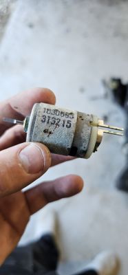
    What kind of electric motor is it? With the number, which is printed on, I can't find anything. Does anyone know where I can get a replacement?
  • ADVERTISEMENT
  • #152 21058570
    roule35
    Level 3  
    >>20135435
    Bonjour,
    Je penses que j'ai le même problème de capteur. J'avais 2 questions sur cette résistance de 10 K Ohms :
    Quelle est sa valeur en watts ?
    Sur quelle partie des fils jaunes tu l'as installée ?

    Merci beaucoup pour ta contribution.

    Hi,
    I think I have the same sensor problem. I had 2 questions about this 10 K Ohm resistor:
    What is its value in watts?
    On which part of the yellow wires did you install it?
  • #153 21066123
    Reflekt
    Level 17  
    Power of resistor 0.25W, you connect in series with the yellow wire at the plug so that it is easy to solder
  • #154 21066785
    roule35
    Level 3  
    You mean like that ?
    A hand holding a bundle of wires with yellow, blue, green, and red wires.
    I have 200 ohms resistance between these 2 yellow wires ...may be the reason of my pressure issue ...

    Another problem to resolve : I only have 0,5 bars on the diagbox computer , seems to be a data connexion issue with the ECU ??
  • #155 21067559
    biuro290
    Level 3  

    Hello
    Gentlemen I will stick to the topic
    The topic started with a boxer from the dog group, but maybe you can help with a car from Fiat.
    I have such a problem. that a message appeared refill adblue fluid. After topping up the fluid (about 12l) the message did not go off. I have only 80km left to drive out of 380km.
    Visit to auto electronics, and they spread their hands. Resetting adblue, checking sensors, levels etc all ok.
    Real readings fine.
    My car is a Fiat Talento 2.0 170km, 2021.
    I thought the renault specialists would help with something (as it's supposedly the same as the traffic), but apparently the electronics are different.
    Maybe someone has encountered this failure.
    Thanks in advance for your help.
  • ADVERTISEMENT
  • #156 21068016
    roule35
    Level 3  

    >>20339688
    Hi, thanks a lot for this experiment. How do you take the voltage on the sensor? I suspect mine is dead too, only 6 ohms resistance. I would like to take the voltage as you but don't know how...
  • #157 21071321
    Reflekt
    Level 17  
    >>21067559
    it may be a faulty fluid level sensor you need to diagnose it preferably on a dismantled tank , above in the posts you have described in detail
  • #158 21073507
    jaros1
    Level 11  
    mako122 wrote:
    >>20290653
    https://www.elektroda.pl/rtvforum/posting.php...tvforum/posting.php?mode=editpost&p=20290653#
    Other readings:

    50.0°C - 3.93 kΩ
    49.0°C - 4.07 kΩ
    .
    .
    .
    1,0°C - 24,90 kΩ
    0,0°C - 25,90 kΩ

    Measurements taken indicate that the sensor located directly on the heating plate is NTC 10,0 kΩ SMD thermistor which serves to protect the plate from overheating in the event that, for example, there is no urea in the tank. which is used to protect the plate from overheating if, for example, there is no urea in the tank and the heating plate starts to operate.


    If I may interject.
    Following this line of thinking, the erroneous indication of the plate temperature sensor (about 700 ohms) should be read by the system as a temp of about 70 degrees, so the power supply to the heating plate will not switch on anyway. Although it is not known whether an actual temperature of 70 deg would already be dangerous for the board. Maybe the temperature limit is set higher and the signal to start heating is information from the fluid temp sensor after all?
  • #159 21074305
    jaros1
    Level 11  
    mako122 wrote:
    michal1226 wrote:
    If there is a problem with communication over CAN then why does the first 30s all information arrive via OBD connector to the diagnostic interface?

    Maybe there is no communication problem just the tank after starting the car tests itself and the test does not pass!!! Then it sends information such as " It does not work properly, for example, I do not detect the circuit of heating urea such and such and please for safety turn me off!!!!! Unfortunately, without knowing the microprocessor software in the tank and its operating logic, it is difficult to say anything sensible. I am convinced that the tank does a check of its circuits and sends a message to the car's central computer.
    What solution do I see?
    If someone has access to a working tank it would be worth doing such exclusion tests.
    Disconnect all sensors and heaters etc from the board. Connect the bare board itself, but 100% working, to the car and see if after 30s it drops voltage, if so, connect other peripherals and by deduction check what causes the voltage drop. In each circuit of urea heating there is a shunt to inform the tank computer whether the circuit has a break or short circuit. That is, the tank computer even monitors such things. It knows if a circuit is working properly or not. All it takes is for one heating circuit to draw too much current or to be short-circuited and this could already be the reason that the tank sends a command to the central computer "turn me off" because I have a faulty heater and cannot continue to work!!!
    Does the system always check the efficiency of the heaters, or only below a certain temperature when Adblue heating is necessary? This would be logical, as at higher temperatures the heaters are not necessary for the system to work.
  • #160 21085565
    edwardboss
    Level 1  

    Hi, I also had a P20a2 and P20e8 error, low pressure etc. The errors were clearing but after a while they came back. With Diagbox, most of the equipment tests passed except for the tank heating and heating the injection line. After removing the tank, it appeared dry and clean with all the electronics. I checked the wires with a multimeter and on the yellow wires not the correct measurement, I soldered a 10 kohm resistor.
    After mounting and flooding the tank, I waited as it says in the instructions, error reset and test. I did several kilometres and zero errors, like the last one after a few kilometres it was giving these errors. After the route I reconnected the Diagbox, zero errors the pump showed a pressure of about 6bar. The appliance test passed ok except for one, heating the line to the injection. I don't know if I missed in this topic checking the tube heater or it was not mentioned.

    What should be the correct resistance on the tube heater to the injector?

    Peugeot 3008 2.0 150km
  • #161 21088255
    pentel
    Level 13  
    Hi,

    problem with Adblue caught up with Peugeot 508. From time to time there was a clogging error on the system, the subject quieted down with the flooding of the tuneup - it has been quiet for over six months. The errors were transient and not signalled by the cluster.
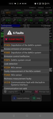
    Recently, a check and urea popped up while driving. From the external symptoms: there was a grey, biting sour smell coming from the exhaust pipe, similar to urea. I immediately set about diagnosing the problem. I found a lot of white residue near the adblue injector - injector to be replaced. From the errors it's leak detection and flooding, no pressure, plus all the kit from the nox probe - screen below.

    Probably the injector flooded adblue into the exhaust in such quantities that it started to burn, hence the white grey smoke and white deposit on the exhaust tip.
    Replacing the injector with a new one seems to have solved the issue, I've done > 300km with no errors, but.... (at the very end).

    The injector itself is an interesting case and a warning. The symptoms could have been indicative of a leaking gasket on the injector, as the whole area around the injector was flooded. Interestingly, I had been to a service quite recently and the area around the injector was clean. The injector itself was not letting water through from the very beginning of the check. after removing it, I started to verify the operation. At the very beginning, passing water under pressure, there was no leakage. After a few open/close cycles, it let air through. Then I repeated the water play - it was leaking. Left the injector under pressure overnight along with the water, drop by drop it ejected all the fluid from the tube.
    The injector did not always close. In summary, the behaviour of the injector is a lottery.

    I also took out the tank - it was remanufactured (sticker from a PL company from remanufacturing). No leaks in the tank, measurement of electrical parameters normal - for the moment I let go of checking the tank further.
    In the diagbox I uploaded information about the replacement of the injector. By the way, I noticed that there is a procedure for testing the adblue output, a procedure described in the TSB to which I do not have access. It shows that the correct dosage of the adblue can be checked.

    The operation was successful - the patient died. Unfortunately, despite the immediate return home, the amount of adblue poured into the exhaust system may have clogged the FAP filter. The filter used to burn out every 400km or so (in mixed urban/urban driving mode), but at the moment the filter burns out every 160km or so - I don't think we can hope for a return to the pre-failure intervals. Below is the list of faults that popped up when the smoke billowed from the exhaust. Then came a leak and low pressure. For those interested I can upload a video of the injector check.

    PEUGEOT BOXER III - Repair of the AdBlue tank PEUGEOT BOXER III, CITROEN JUMPER
  • #162 21113610
    308t9ish
    Level 1  

    newer versions of the tanks are being supplied with v4.0 software on them and these have the yellow sensor wires missing. is there any way to download the software off a newer tanks using the flashing tool?
  • ADVERTISEMENT
  • #163 21115569
    mitchcisco7
    Level 1  

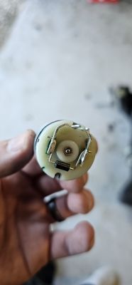
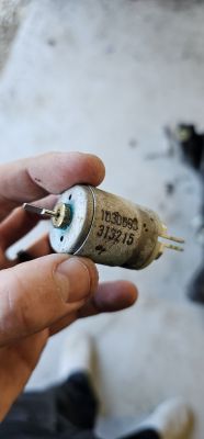
    Hi, has anyone been able to source a new pump motor? The bushes have broken off of my current motor and the motor has seized. I was wondering if there is a replacement motor available out there that would work in its place? The code on the Motor does not refer to anything on Google (That I can find).
    Any help on this would be greatly appreciated.
    Thanks.
    Close-up of a damaged pump motor held in a hand. Person holding a small electric motor with markings 103088 and 913215. Small electric motor held in hand with visible number 313215 on the casing.
  • #164 21116222
    gemiel
    Level 25  
    mitchcisco7 wrote:
    .
    Hi, has anyone been able to find a new pump motor? The bushings in my current engine have broken and the motor has seized.
    .

    First of all, you need to get a new simulator, which seals the engine shaft. It is through its wear that the adBlue enters the pump. This is why the motor is primed first and then the entire electronics.
    Unfortunately, I have not been able to find such small simulators or motors anywhere. The motor can be used recycled, the sealer unfortunately not.
  • #165 21116271
    mako122
    Level 12  
    mitchcisco7 wrote:
    .
    Hi, has anyone been able to find a new pump motor? The bushings in my current engine have broken and the motor has seized. I was wondering if there is a replacement motor available that would work instead? The code on the motor doesn't refer to anything on Google (that I can find).
    Any help on this would be greatly appreciated.
    Thanks.
    .
    The easiest way is to buy a damaged whole tank on allegro. The price is around 300 zł and you will not only have the engine but also many other spare parts. You should only agree with the seller that the tank is not flooded, but has other damage such as electronics or sensors. In this case, the engine and pump will almost certainly be in working order. It will be cheaper than buying an engine somewhere and then having to combine them.
  • ADVERTISEMENT
  • #166 21117103
    ShadowSAF
    Level 4  
    Hi,
    I have now the U029D fault .. i tried now already 3 tanks, and they are not getting recognized. On the Cable to the Urea tank i can measure 12V... Where does this cable end? Is there any kind of fuse to check?

    I'm having a Citroen Grand Picasso C4 from 2016
  • #167 21128609
    sperma
    Level 11  
    Welcome,

    First of all, respect for your analysis on this topic !!!!

    I have a 2016 peugeot 308 2.0 hdi automatic. The car has a mileage of 83 thousand km. Some time ago an error appeared to me, known to all in this topic of this forum P20E8- urea pressure.

    On the display of course the Christmas tree check engine and service and urea light.

    Plug from adblue new type.
    Db shows 4 bar.
    So far I have checked the injector and the pipe from the tank to the injector is unobstructed.
    I quickly dismantled the adblue tank, unscrewed the pump. I didn't see any leakage or traces of urea on the plate.

    I added urea under the cap, did a urea drain and still the error pops up.
    One thing puzzles me.
    Db shows with full tank in position
    "Volume of urea liquid remaining in the urea tank - incorrect value.
    As I drained all the fluid from the tank wanting to flush it with warm water it showed a value of 0,000.
    I filled the tank again and still the value was wrong.
    As I was cleaning the tank I could hear the float moving. But the puzzling thing is this result with a full tank.

    I have another conundrum.

    The "urea line heating" test - result of heating failure.
    Test "heating of urea tank"-result also failure of heating.

    Db, however, despite these negative tests in the option:
    "Authorisation of urea fluid injection based on temperature"-result- authorised injection.

    "Temperature of urea fluid in the urea tank - always shows 0*C. Recently it seemed to me that it showed 22*C for a while, but after refreshing it was constantly 0*C.

    Apparently these two heating tests are negative, but it allows injection.

    I am also puzzled by another point in the test:
    "NOX system relay control test" a noise should be heard. The result is successful, no defect, but I do not hear the noise.

    If, for example, there is a "test of the urea injector control", noise should be audible - the result is noise.

    I think that as the db will see the adblue level may improve something, because systemically it has an unknown value so far.

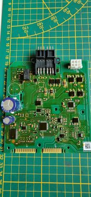
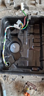
    It also makes me wonder:
    "NOX system pressure build-up control"-result- stuck clutch pedal, and it is an automatic after all.... Wondering what I can do to make this test give some result.

    Another conundrum:
    "NOX system vent check" - no result, the program comes right out to select individual tests.

    "Operating status of the NOX system"-result of the indicator-pump urea module switched off at blank.

    This is so far what comes up for me.

    For now, I wanted to check all the components before I got down to checking the electronics.
    But under this heading. "Volume of urea fluid remaining in the urea tank" is commented on from the photo in the appendix, so it's as if there's something wrong here, but it puzzles me that with the tank empty the value is given as zero but the value shows something.

    Thank you in advance for any guidance
  • #168 21128836
    mako122
    Level 12  
    >>21128609 .


    I don't know which AdBlue level sensor you have. There are supposedly several versions. If you have one like the one described in this thread then check that it works properly. To start with, check two states.
    You check on an empty tank.
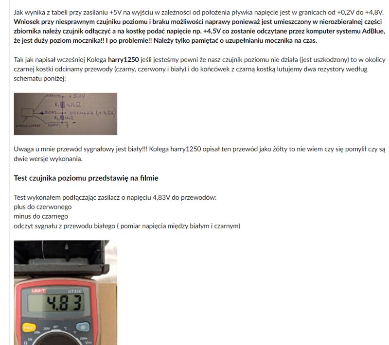
    Disconnect the 3 wires from the sensor from the electronics board and do as described in this thread above. Just power the sensor from a 4.5V flat battery and read with a voltmeter what the voltage is on the third signal wire. You do this in two positions of the tank.
    The tank in the "normal" position and the second position the tank turned upside down" and you read in these positions what the voltage is on the signal wire. If the tank passes this test, you can do a thorough test of this sensor by filling the tanks slowly with water and observing how the voltage on the signal wire changes. How to do this you have a description above in this thread. I hope I have described it clearly. If not then write boldly I can also help you with a phone call on how to do this.

    Read the description in this thread from what you have in the picture below. There is also a video on the sensor test there.


    Screenshot from a forum with a description of an AdBlue level sensor test and an image of a meter displaying voltage. .
  • #169 21128890
    sperma
    Level 11  
    Thank you mako122 for your quick response.

    There's a sticking point, I'll keep digging into the topic, if I have any questions I'll be sure to get back to you.

    Another thought occurred to me yesterday.
    Since Db was seeing an empty tank condition and not seeing a full one, I started draining the urea slowly because I want to capture the level where some numerical value will appear. About 5 litres went down yesterday and still an unknown value.
    I'm going to keep draining and see what happens. Once the tank is empty, I'll get on with the measurements you wrote about.

    Regards
  • #170 21128991
    mako122
    Level 12  
    >>21128890 .

    This sensor works completely differently to the fuel level sensor.
    The fuel level sensor measures the fuel level from full to empty, i.e. over the entire range.
    The sensor in the AdBlue tank only measures within a very narrow range that is crucial for the operation of the system. It only measures within a range of 3 cm
    If the maximum level is 20cm, it measures between 5cm and 8cm. Therefore, when the tank is emptied slowly, nothing happens for a long time until the key level of 8 cm is reached and then the measurement is taken down to 5 cm, after which there is no change.
  • #171 21129399
    sperma
    Level 11  
    >>21128991 .

    Doing as you wrote with an ac voltage of 5.99 V.
    Between white and black:
    - on an empty tank: 0,54 V,
    - on a flooded tank (poured about 10 l) where the value no longer
    increased: 5,30 V.

    What else can be checked, and could be the cause of the incorrect display of the urea quantity?
  • #172 21129451
    jaros1
    Level 11  
    >>21129399 .
    I don't know if you have read the whole conversation carefully but it was already written that the fluid level sensor does not measure from the full tank but only the end of the tank. DB states "Volume d'urée supérieur à 6 litres" meaning "Volume of urea greater than 6 litres". It is only when the level drops below 6L that accurate metering begins.
  • #173 21129469
    mako122
    Level 12  
    >>21129399 .

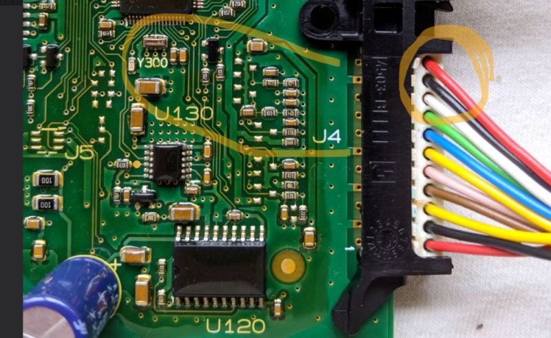
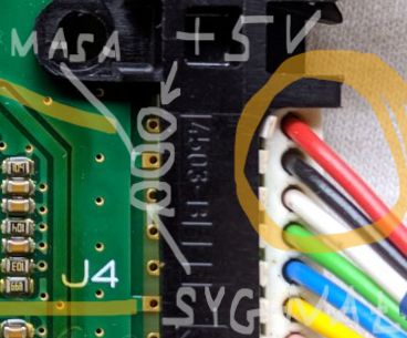
    This means that the level sensor is working correctly. You can still check with an ohmmeter whether there is a correct transition of these three wires to the contact point on the electronics board. whether there is any damage there. You can also replace the level sensor with two resistors according to the diagram in the photo above as a test. You will be sure where to look for the problem. If you insert the two resistors as shown in the diagram right near the edge connector, you will not only bypass the sensor itself, but also the whole path from the sensor to the edge connector, because there is also another connector on the way.
    Check under a magnifying glass whether there are any printing defects in the area of the edge connector (no copper path) or whether the edge connector itself is damaged. You can also apply 12 V to the board (supply power to the whole board and check that there is +5 V on the wires to the sensor (if the sensor is powered).

    Of course, if you want to replace the level sensor with resistors then you have to cut these three wires near the edge connector (cut the sensor off) and solder these two resistors to the ends going to the edge connector. (Maybe I shouldn't write about this, but a colleague has already soldered these resistors without cutting off the sensor, so I prefer to point this out because not everyone is an electronics technician)

    Check the area of the board circled in yellow and the wires marked in the yellow circle.
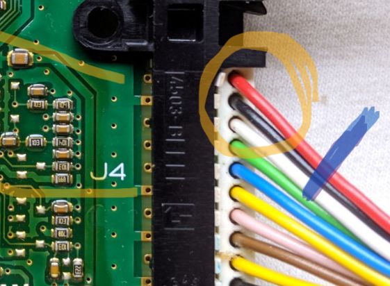
    You can cut these three wires here where I have marked in the circle and solder the two resistors here.

    Image of a circuit board with a marked section and a bundle of wires. .

    I have marked the cut lines of the three wires in blue and at this point to be sure there is a transition to the sensor do the sensor test you have already done. This black edge connector should be unplugged from the board and checked for dirt. It is a good idea to wash it with extraction benzine or, even better, CONTACT-CLEANER for the contacts.

    Close-up of a circuit board with marked wire section. .


    Close-up of a circuit board with an edge connector and marked wires.
  • #174 21132140
    sperma
    Level 11  
    >>21129451 .

    Yes I know, I have already read this and on my tank I have verified it, the voltage values changed up to about 10l pour.

    Added after 8 [minutes]:

    >>21129469 .

    I'm waiting for the resistor and will act.
    The board looks very bare to the naked eye but with a magnifying glass I will check.

    Checking on the dashboard with the 000 button how many km left to run on adblue I came up with (with full tank) over 5000 km. Is this the maximum amount the computer can show? Is it only showing that much due to the unknown level of urea?
  • #175 21132702
    mako122
    Level 12  
    >>21132140 .

    The computer when the float is in the maximum upper position shows (depending on the car model, because it is usually different in each, it depends on the engine power and the capacity of the AdBule tank) that you can still drive more than 5000 km. It is only when the float begins to fall that the precise measurement takes place until the float reaches the lower position, and when this happens, the warning message "Fill up with AdBlue, because you can only drive e.g. 400 km" appears. In this situation, you get a message on the dashboard every, say, 50 km saying "top up with AdBlue".

    In summary, the computer will not show more than 5,000 km because it is not possible to do so, this is due to the design of the tank and the level sensor.
  • #176 21135131
    sperma
    Level 11  
    >>21129469 .

    I disconnected the float, soldered resistors with specific values in the indicated places and connected the tank. Still the amount of urea in the tank - value unknown.
    Now it's time to verify the board.
  • #177 21135311
    ShadowSAF
    Level 4  
    Is there actually a way to verify if the board itself is actually working?
  • #178 21136876
    mako122
    Level 12  
    >>21135311 .

    This is a very difficult matter because of the lack of access to documentation, software etc.

    And what is the error? Because maybe it is not about the AdBlue level maybe the cause lies elsewhere.
    I have had different errors P20f6 in a moment P2a00 or P20e8 and the cause was the same.
    What errors do you have?
  • #179 21137055
    szustakowski
    Level 2  
    Good morning,
    It got me too, the car is a Peugeot 308 SW, 2.0 HDI, 2016.
    Error 20E8. Alpine combinations of DB like colleagues from 308 brought exactly the same test results and the same behaviour and readings. Here is my observation, DB does not quite handle the 308. Hence perhaps the misleading missing test results of e.g. the line heater to the injection and the injection itself.

    I passed the tank, passed the cap, clean dry and no leaks or efflorescence.

    I am not an electronics technician so I will say what I was able to check.
    1. the heaters (4) at the pump itself give readings of 17 or 50 ohms
    2. the heater of the cable connecting the tank to the pump something around 28 ohms
    3. the tank heater about 1.8 ohms
    4. blue thin at grey plug, 2.61 kohm but at 28°C
    5. yellow at grey plug 275 ohms, also at 28°C
    6. black plug, between white/black wires about 800, between black/red 800, between red/white.... one way 2.8 Mohm, the other almost 9Mohm.... Or am I measuring something wrong.

    7. the non-return valve when voltage is applied works ok

    8. pump works both ways after applying voltage

    I don't think I know how to measure the rest 🙂 .

    Photo of the board.... looks OK.

    And the pump chamber, does that white thing (I think it's a filter) open and clean somehow?

    Have you noticed that when the weather gets hot there's a rash on the respective brand forums that AdBlue has gone to shit?

    Electronic circuit board on a measuring mat View of the interior of the pump casing with electrical wires in a Peugeot 308 SW car.
  • #180 21140408
    bbmax
    Level 15  
    see on the electronics housing what version of SW it is as 3.2 you have to flash the electronics

Topic summary

The discussion revolves around the repair and troubleshooting of the AdBlue tank in PEUGEOT BOXER III and CITROEN JUMPER vehicles. Users share their experiences with common issues such as low pressure errors (P20E8), sensor malfunctions, and the need for system resets. Key solutions include replacing or bypassing faulty sensors, particularly the heating plate temperature sensor, and ensuring proper electrical connections. Users emphasize the importance of checking for urea crystallization and leaks, as well as the necessity of clearing error codes after repairs. The conversation also touches on the complexities of the AdBlue system's electronics and the potential for DIY repairs using resistors to simulate sensor readings.
Summary generated by the language model.
ADVERTISEMENT