logo elektroda
logo elektroda
X
logo elektroda

PEUGEOT BOXER III - Repair of the AdBlue tank PEUGEOT BOXER III, CITROEN JUMPER

mako122 153402 224
ADVERTISEMENT
Treść została przetłumaczona polish » english Zobacz oryginalną wersję tematu
  • ADVERTISEMENT
  • #62 20312572
    mako122
    Level 12  
    I am looking for a pressure sensor to take measurements and develop a topic about this sensor.
    I have a measuring stand prepared, but the sensor I have is probably damaged.
    If anyone has such a sensor, please let me know. I can buy such a sensor or return it after testing.
    Of course, I'm not doing these tests just for myself. I will post all the information and results of measurements in this thread.
  • #63 20313669
    bbmax
    Level 15  
    I'm wondering what fix tool and flasher with tank Schematic illustration of using the SCR_FixVAccuTool_APV program with CAN module and PC.
  • #64 20314024
    mako122
    Level 12  
    bbmax wrote:
    I'm wondering what fix tool and flasher with tank


    Can you write more about it?
    Any links?
    Price?
    Documentation?
  • #65 20314378
    melas
    Level 31  
    I'll see what I have in stock on Monday, see if I can find a good one, we'll think about it
  • #66 20314824
    mako122
    Level 12  
    melas wrote:
    I'll see what I have in stock on Monday, see if I can find a good one, we'll think about it


    I have everything ready for measurements. It is a pity not to take measurements and I got a little tired to choose the right pressure hoses of the band and make a good connection with the compressor. I prepared it so that you don't even have to remove the sensor from the system. By the way, you can check the tightness and even hear how the piston in the battery works.
  • ADVERTISEMENT
  • #67 20315439
    bbmax
    Level 15  
    mako122 wrote:
    bbmax wrote:
    I'm wondering what fix tool and flasher with tank


    Can you write more about it?
    Any links?
    Price?
    Documentation?


    well, the price is a downside here because at the dealer 950 euros for the programmer and 280 eu for a piece of cable :) with plug
    partial documentation...
  • #68 20316623
    mako122
    Level 12  
    bbmax wrote:
    mako122 wrote:
    bbmax wrote:
    I'm wondering what fix tool and flasher with tank


    Can you write more about it?
    Any links?
    Price?
    Documentation?


    well, the price is a downside here because at the dealer 950 euros for the programmer and 280 eu for a piece of cable :) with plug
    partial documentation...


    I encourage everyone who has a little desire and knows how to hold a screwdriver in their hand to repair this tank at home. It turns out that the devil is not as scary as he is painted!!
    No special tools needed. That's a big plus. The hoses are quick couplers so that removing the tank from the car is not a problem and what is important during the repair of the tank you can use the car at least for some time.
    I would divide the repair and testing into 4 stages.
    - visual inspection of the tank (pump, wiring, electronic board, looking for leaks, white tarnish from urea crystals, burnt elements, etc.
    - checking the part to which we do not have access (temperature, level and heating plate sensors) is a simple matter
    because in this thread everything is described how to check what values should be etc.
    - checking the urea heating circuits - also a simple matter, the resistances of individual heating loops are known.
    - checking the engine, pump, solenoid valve, pressure sensor (testing of this sensor is currently being developed),
    urea accumulator.
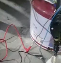
    Checking the motor and thus the pump is not difficult. It is enough to supply +12 V to power the motor. By swapping the plus and minus on the motor power supply, we change the direction of the pump's operation and thus the direction of the water flow. If we want to check whether the pump is pumping urea (we use water for tests, of course), then before turning on the pump motor, power should be applied to the solenoid valve (in my case, it is enough to give +5V) because the solenoid valve is right behind the pump and if it is closed, the pump has no chance to pump water to the further part of the system (to the accumulator). If we want to pressurize the system, it is of course necessary to close the water outflow by installing a pressure gauge with a measuring range of 0 to 8 bar with a relief valve at the outlet of the system (on the pipe through which urea is fed to the injector). When the pressure gauge shows a value of about 6.5 - 7.0 bar, disconnect the power supply from the solenoid valve, thereby closing the solenoid valve and immediately after that disconnect the pump from the power supply. Now we can check the tightness of the system, especially the battery which in its construction has a rubber cap that can be damaged over time. The pressure should stay the same all the time. In the further part of the test, very slowly drop the water through our bleed valve (including the pressure gauge wheel) and observe the behavior of the system. Initially, despite the water being dropped (literally in drops - we simulate the operation of the injector in this way), the pressure is relatively constant because the water flows out of the accumulator in which there is a spring with a plunger. The spring, despite the water being drained, prevents the pressure drop. After dropping a few cubic centimeters of water, the pressure begins to drop rapidly because the accumulator is completely empty and there is nothing left to maintain this pressure. The test performed in this way gives us a guarantee that the hydraulic system of our tank works properly. When performing this test, you can try to check the pressure sensor and note the voltage changes on its signal output.

    You can also perform a simple motor and pump test as a start. Like in the video (from 2:08):

    https://youtu.be/gqEmQYziu9M

    In the film, the motor was powered in reverse and works "backward" and the water is pumped in the opposite direction than in normal operation.

    The pictures show that not only the motor but also the solenoid valve is connected to the battery:

    PEUGEOT BOXER III - Repair of the AdBlue tank PEUGEOT BOXER III, CITROEN JUMPER PEUGEOT BOXER III - Repair of the AdBlue tank PEUGEOT BOXER III, CITROEN JUMPER

    If everything is fine, then you should suspect a damage to the electronic board. Its repair at the current stage of our knowledge without documentation is possible, but to a rather limited extent. Nevertheless, you can check the final power elements that control the heating plate, urea heating circuits, motor, check the relay, etc. The situation is worse with the microprocessor and software. If the plate is damp, splashed with urea, you can try to clean and dry it. If the urea has not managed to damage the paths and elements, there is a chance that it will work.
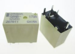
    It is best to wash the plate with plain hot water, you can help yourself with dishwashing liquid. Rinse directly under the tap, do not use high pressure because you can pick up the elements. You can help yourself with a soft brush. Go ahead and rinse under water without fear, a proven method more than once!! After washing, gently blow with compressed air from a safe distance and expose the plate to strong sun to dry (in summer), in winter use a hair dryer. The plate should be quite hot. Don't worry, nothing will happen to her. After such washing, check the plate in detail using a magnifying glass. It is often possible to find urea-eaten paths that can be repaired. I've managed to save the tile a few times this way. I advise against using extraction gasoline or similar preparations (for cleaning contacts, etc.). Water is the ideal solvent to remove urea crystals and dirt. It's worth doing because we have nothing to lose. A wet tile splashed with urea sooner or later will stop working. The sooner we remove the urea, the less damage will be. Please do not try to dry the plate locally with cotton pads, etc. It won't do anything!!! Urea often gets under integrated circuits and other elements and if it stays there it will destroy the tracks. The only rescue is to perform a general cleaning of the entire plate. You have to do it quite efficiently and intensively rinse with water so as not to soak the plate in water for hours. The only element that you should pay attention to is the relay that water should not get into. Typically, these relays are hermetically sealed, but there are also relays with a removable cover and you have to be careful with them. I have always met a hermetic relay in this place, which is 100% tight, non-demountable, flooded with resin, as in the picture below:

    PEUGEOT BOXER III - Repair of the AdBlue tank PEUGEOT BOXER III, CITROEN JUMPER
  • #69 20319592
    mako122
    Level 12  
    Detailed description of the urea heating system in the tank itself and throughout the urea flow path up to the injector. There are 7 urea heating circuits in the AdBlue system: .

    I include the correct resistance values of all circuits here before describing them in detail:

    (A) urea heating plate in the tank (there is no direct access to it) - 1.3 Ω
    B) wire connecting the urea filter to the pump assembly (about 30 cm long) - 27.0 Ω
    C) "green" circuit heating the pump - 55.0 Ω
    D) "yellow" circuit heating the solenoid valve - 55.0 Ω
    E) "blue" circuit urea accumulator heating - 212.0 Ω
    F) "white" circuit heating the elbow where the urea exits the tank - 22.0 Ω
    G) circuit heating the tube between the tank and the injector ( about 1.5 m) - 2.5 Ω

    I will start the description with four circuits that are closely related to each other both in terms of function and control.
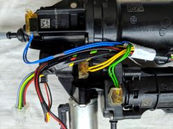
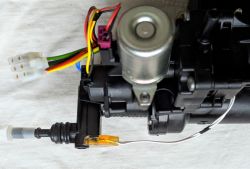
    These are circuits C, D, E and F. These four circuits heat the body of the entire hydraulic assembly (pump + solenoid valve + pressure sensor + accumulator). Some of the most sensitive areas of the body where urea could freeze in winter are heated. The photo shows these circuits (the circuit is named after the colour of the wires supplying it):

    PEUGEOT BOXER III - Repair of the AdBlue tank PEUGEOT BOXER III, CITROEN JUMPER PEUGEOT BOXER III - Repair of the AdBlue tank PEUGEOT BOXER III, CITROEN JUMPER .

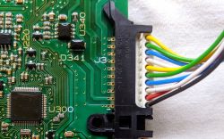
    The wires feeding these four circuits directly reach edge connector J3 on pins numbered 3 to 10


    PEUGEOT BOXER III - Repair of the AdBlue tank PEUGEOT BOXER III, CITROEN JUMPER

    Contacts 1 (ground) and 2 (+12) are the power (control) to the solenoid valve.

    As you can see in the picture, all four circuits have the minus and the plus connected together. Thus, they can only be controlled together and constitute one heating circuit for the control system with a resultant parallel resistance of 11.6 Ω. In summary, the control processor can always switch these four circuits on and off at the same time! For the same reason, it controls these four circuits as if it were one circuit. If one circuit is faulty, it considers all four circuits to be faulty!!!
    With the above-mentioned circuits, circuit B should also be discussed because it is controlled by the same integrated circuit.
    The B circuit heats the tube running from the urea filter to the pump and terminates in a black cube which, via an additional connector, eventually reaches connector J2 on the board. On the J2 connector, the grey-red pair of wires is what supplies the B circuit.

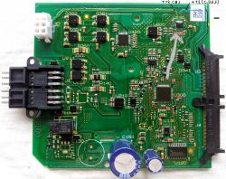
    The U230 IC is responsible for controlling these circuits:

    PEUGEOT BOXER III - Repair of the AdBlue tank PEUGEOT BOXER III, CITROEN JUMPER .

    Please click on the photo and see the control details.

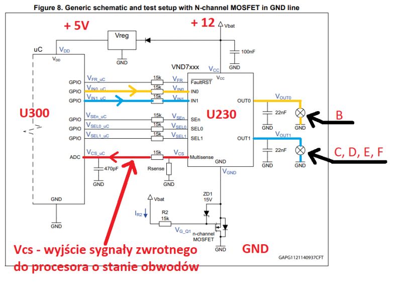
    The U230 chip is a typical integrated circuit widely used in the automotive industry to control either incandescent bulbs especially double filament bulbs or two single filament bulbs in lights such as stop, parking, turn signals etc.
    The system is characterised by the fact that it has two independent control circuits in one housing. It is controlled directly from the processor. The second important feature of this system is that it not only controls the but feedback to the processor about the state of the controlled device because it measures the current flowing in the controlled circuit. Therefore, if a bulb in the car burns out, we get a message on the dashboard such as "left rear indicator defective".
    It is no different in the tank. The U300 processor directly controls the U230 circuit, which has two sections, one of which activates heating circuit B (yellow line on the photo) and the other section activates circuits C, D, E, F (together, as one circuit - blue line on the photo). The processor is constantly receiving feedback from the U230 controller as to what state the circuits of both sections are in.
    In summary, the heating circuits are not only switched on but are also controlled by the processor. The processor knows what current flows in these circuits when the 'switch on circuit' command is issued. Therefore, in order for the tank to work correctly, the heating circuits must work correctly because if there is a short circuit somewhere or an open circuit, the processor will switch off the tank and send a message about a faulty AdBlue system. Switching off the tank causes errors P20E8 - low urea pressure .

    For the curious!! .
    Block diagram of the U230 circuit ( VND7140AJ12 - dual channel high-side with MultiSense analogue feedback ) and an excerpt from the block diagram of the U300 which controls, among other things, the U230 :


    PEUGEOT BOXER III - Repair of the AdBlue tank PEUGEOT BOXER III, CITROEN JUMPER .

    There are heating circuits in place of the bulbs in the tank!!!

    As you can see, all tank circuits need to be working properly for the tank to operate correctly. The processor feedback controls each circuit and if we have a preheating circuit or a sensor that is faulty, this circuit must be repaired or the processor must be skilfully fooled if possible. In the case of a liquid level sensor it is very simple, you can give the appropriate voltage and trick the processor, but in the case of circuits heating urea it is impossible, because here the process is dynamic and you cannot permanently feed the processor with a simulated value. Here you have to keep up with the processor's commands all the time. The only thing that can be done is to replace the heating circuit with a resistor of the same value, but this does not make much sense due to the power dissipated on such a resistor.
  • #70 20321404
    mako122
    Level 12  
    I renew my request:

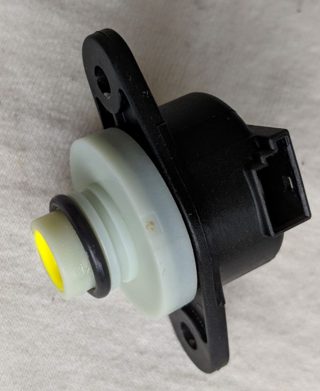
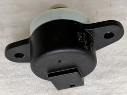
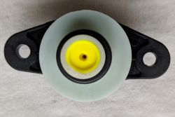
    I am looking for a pressure sensor (probably this sensor has a commercial designation: HM8500C SCR Urea Pressure Sensor) https://www.ever-smart.com/product/99.html

    In order to take measurements and develop a topic about this sensor.
    I have a measuring stand prepared, but the sensor I have is probably damaged.
    If anyone has such a sensor, please let me know. I can buy such a sensor or return it after testing.
    Of course, I'm not doing these tests just for myself. I will post all the information and results of measurements in this thread.


    PEUGEOT BOXER III - Repair of the AdBlue tank PEUGEOT BOXER III, CITROEN JUMPER

    PEUGEOT BOXER III - Repair of the AdBlue tank PEUGEOT BOXER III, CITROEN JUMPER

    PEUGEOT BOXER III - Repair of the AdBlue tank PEUGEOT BOXER III, CITROEN JUMPER


    Model No.: HM8500Jplace of origin: Chinause: Pressure Sensorprinciple: Resistance SensorOutput: Analog SensorAmplifier type: Analog Outputjack: Analogtechnology: Resistive
  • #71 20322108
    bbmax
    Level 15  
    If I had, I would send you a free flasher for now.. PEUGEOT BOXER III - Repair of the AdBlue tank PEUGEOT BOXER III, CITROEN JUMPER PEUGEOT BOXER III - Repair of the AdBlue tank PEUGEOT BOXER III, CITROEN JUMPER
  • #72 20323521
    mako122
    Level 12  
    bbmax wrote:
    If I had, I would send you a free flasher for now..


    Please write more about it. Do you have any documentation? any software?
  • #73 20324820
    st.sitarz
    Level 12  
    Good morning Hello everyone. Great respect for the work done and documentation.
    I have a question, maybe someone has a quick connector for sale, or rather a gray cotter pin that I marked in the picture. This is the connector of the AdBlue output pipe from the tank to the injector (Peugeot 5008 II). Thank you in advance.
    PEUGEOT BOXER III - Repair of the AdBlue tank PEUGEOT BOXER III, CITROEN JUMPER
  • ADVERTISEMENT
  • #74 20325044
    mako122
    Level 12  
    st.sitarz wrote:
    Good morning Hello everyone. Great respect for the work done and documentation.
    I have a question, maybe someone has a quick connector for sale, or rather a gray cotter pin that I marked in the picture. This is the connector of the AdBlue output pipe from the tank to the injector (Peugeot 5008 II). Thank you in advance.
    PEUGEOT BOXER III - Repair of the AdBlue tank PEUGEOT BOXER III, CITROEN JUMPER


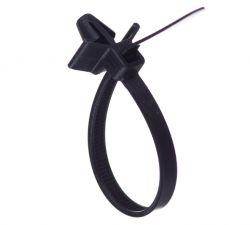
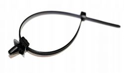
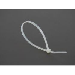
    This gray part is rather not a cotter pin, but a band that holds the cable, such a tourniquet (tytka)?
    I think right? If so, you can replace the original one with something else. This is not a cotter pin in my opinion that must be matched to the factory wire. I would have a good look around the car chassis, such holders are widely used to support cables, pipes, etc. They are scattered throughout the chassis. You can remove such a handle from another place where it is not so needed and put it near the tank because here it may be necessary because it not only holds the tube but also protects against falling out.

    PEUGEOT BOXER III - Repair of the AdBlue tank PEUGEOT BOXER III, CITROEN JUMPER

    PEUGEOT BOXER III - Repair of the AdBlue tank PEUGEOT BOXER III, CITROEN JUMPER

    PEUGEOT BOXER III - Repair of the AdBlue tank PEUGEOT BOXER III, CITROEN JUMPER

    Something like that?

    PEUGEOT BOXER III - Repair of the AdBlue tank PEUGEOT BOXER III, CITROEN JUMPER PEUGEOT BOXER III - Repair of the AdBlue tank PEUGEOT BOXER III, CITROEN JUMPER

    https://allegro.pl/oferta/10-x-uchwyt-opaska-..._campaign_id=17303547827&network=x&placement= &test=pmax&category=heating&gclid=CjwKCAiAs8acBhA1EiwAgRFdwxukTAKz2j3uXGH-LTlPndYCbF9ndeetL7_qUvnmWwSMmsWjfDVXQBoCj_AQAvD_BwE
  • #75 20325238
    st.sitarz
    Level 12  
    I'm not talking about supporting the cable, but about the element (latch) that protects the connector from slipping off the connector. PEUGEOT BOXER III - Repair of the AdBlue tank PEUGEOT BOXER III, CITROEN JUMPER
  • #76 20325608
    kinzo85
    Level 2  
    st.sitarz wrote:
    Good morning Hello everyone. Great respect for the work done and documentation.
    I have a question, maybe someone has a quick connector for sale, or rather a gray cotter pin that I marked in the picture. This is the connector of the AdBlue output pipe from the tank to the injector (Peugeot 5008 II). Thank you in advance.
    PEUGEOT BOXER III - Repair of the AdBlue tank PEUGEOT BOXER III, CITROEN JUMPER

    Hi, I can repair with plastic welding technology.
    If you send me, I fixed it!
  • #77 20328155
    ZlPu
    Level 2  
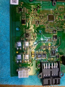
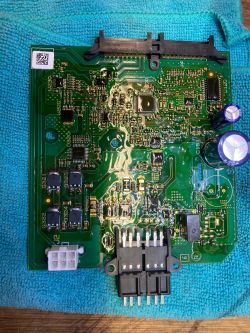
    Hello, I have read all your posts carefully, my Peugeot 508 2.0HDI 2015 with SCR also has the P20e8 error and the starter block after 1100. I checked all the sensors and actuators according to the instructions, no errors. Everything is sealed. But the pump doesn't work.

    The temperature sensor on the heater in the tank showed incorrect values, at 15 ° C 400 Ohm (should be approx. 14K) These temperature sensors can be resuscitated with 5V. Just connect - alternately, it worked for me. Since then, the sensor shows acceptable values. After the heater was connected to the voltage, the resistance changed analogously to the temperature, it fits!

    But the pump still didn't work.
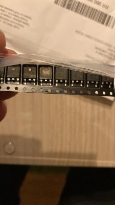
    As another error, I detected one of the MosFet transistors (H-bridge). The system must always be turned off empty (tank and wires must always be empty) to prevent freezing and crystallization of the fluid in the system. Therefore, the direction of rotation changes (H-bridge)

    I bought the transistors on eBay (from Poland), they are hard to get.
    PEUGEOT BOXER III - Repair of the AdBlue tank PEUGEOT BOXER III, CITROEN JUMPER

    I bought the transistors on eBay (from Poland), they are hard to get.
    link
    PEUGEOT BOXER III - Repair of the AdBlue tank PEUGEOT BOXER III, CITROEN JUMPER

    After soldering and reassembling the system, everything worked again.
    PEUGEOT BOXER III - Repair of the AdBlue tank PEUGEOT BOXER III, CITROEN JUMPER

    The pump only starts when the engine reaches operating temperature. The pressure rises to 6 bar and is maintained. Only when the pressure drops below 5 bar (urea injection) does the pump build up pressure again. Above 80/100km/h there is no injection (but I didn't check it fully)

    All parameters that I measured with DiagBox are acceptable

    injection amount
    injection time
    Emphasis
    temperature
    system status

    I'm in Germany, Polish translation can be a bit difficult ?


    Zlatan
  • #78 20328794
    mako122
    Level 12  
    ZlPu wrote:
    But the pump still didn't work.
    As another error, I detected one of the MosFet transistors (H-bridge). The system must always be turned off empty (tank and wires must always be empty) to prevent freezing and crystallization of the fluid in the system. Therefore, the direction of rotation changes (H-bridge)


    ZIP's friend confirmed what I described earlier, that the pump works in two directions and that's why it has such a rather complicated power supply system (H-bridge). The second remark that comes to mind is another confirmation of the fact that the tank checks not only the efficiency of the sensors but also the pump motor. All circuits are backward protected. The processor checks every circuit and therefore all tank controls and controls should be tested. The same applies to the control of the solenoid valve, also the executive system is a specialized controller that sends information about its status back to the processor. The feedback output is positive to ground proportional to the current flowing through the solenoid coil. Such accurate information allows not only to assess whether there is a break or short circuit, but also to assess exactly what current the solenoid valve draws during operation.
  • #79 20332048
    kinzo85
    Level 2  
    bbmax wrote:
    If I had, I would send you a free flasher for now.. PEUGEOT BOXER III - Repair of the AdBlue tank PEUGEOT BOXER III, CITROEN JUMPER PEUGEOT BOXER III - Repair of the AdBlue tank PEUGEOT BOXER III, CITROEN JUMPER


    What is this?

    Added after 4 [minutes]:

    mako122 wrote:
    I renew my request:

    I am looking for a pressure sensor (probably this sensor has a commercial designation: HM8500C SCR Urea Pressure Sensor) https://www.ever-smart.com/product/99.html

    In order to take measurements and develop a topic about this sensor.
    I have a measuring stand prepared, but the sensor I have is probably damaged.
    If anyone has such a sensor, please let me know. I can buy such a sensor or return it after testing.
    Of course, I'm not doing these tests just for myself. I will post all the information and results of measurements in this thread.


    PEUGEOT BOXER III - Repair of the AdBlue tank PEUGEOT BOXER III, CITROEN JUMPER

    PEUGEOT BOXER III - Repair of the AdBlue tank PEUGEOT BOXER III, CITROEN JUMPER

    PEUGEOT BOXER III - Repair of the AdBlue tank PEUGEOT BOXER III, CITROEN JUMPER


    Model No.: HM8500J place of origin: China use: Pressure Sensor principle: Resistance Sensor Output: Analog Sensor Amplifier type: Analog Output jack: Analog technology: Resistive


    hi!
    i have a tank! I haven't checked it yet, but maybe the heating NTC is faulty. The problem is that I live in Hungary, the country of pálinka...
    I have some ideas for doing tests!
  • #80 20332354
    wrzosek
    Level 2  
    My solenoid valve only opens at 8v. Is it good?
  • #81 20332375
    mako122
    Level 12  
    wrzosek wrote:
    My solenoid valve only opens at 8v. Is it good?


    For me, it already opens at 5V, but I tested after removing it from the hydraulic unit. I suggest disassembling it to see if there is any dirt or urea crystals there. It is worth doing such an inspection and washing the socket with water. When installing these O-rings, lightly lubricate them with silicone oil. you can buy for a few zlotys such oil for lubricating rubber seals that does not damage rubber. I use this oil and it's ok:

    https://termopasty.pl/produkty/silicone-oil/

    Ordinary grease reacts with the rubber and the seals swell.
  • ADVERTISEMENT
  • #82 20332635
    wrzosek
    Level 2  
    I did the tests yesterday after removing the pump valve accumulator assembly.
    Pump power supply 12v, solenoid valve 4.8 (three fingers) - the pump is spinning, the valve is not open.
    Pump 12v power supply, solenoid valve removed - the pump sucked water very quickly.

    Today, using a power supply with adjustable voltage, I measured that the valve is fully open at 7 volts.

    What voltage does the control board provide to the solenoid valve?
  • #83 20332701
    mako122
    Level 12  
    wrzosek wrote:
    I did the tests yesterday after removing the pump valve accumulator assembly.
    Pump power supply 12v, solenoid valve 4.8 (three fingers) - the pump is spinning, the valve is not open.
    Pump 12v power supply, solenoid valve removed - the pump sucked water very quickly.

    Today, using a power supply with adjustable voltage, I measured that the valve is fully open at 7 volts.

    What voltage does the control board provide to the solenoid valve?


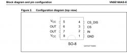
    The solenoid valve is controlled by a system marked on the plate U340 it is VN5E160A.
    This system is powered with +12 voltage (pins 5 and 8 are plus power supply) and pins 6 and 7 are shorted together and this is OUT, i.e. the solenoid valve control output (red wire). The copper path on the board that powers the system is quite narrow, I bet that the valve is powered at 99% with 12V, because at low voltage it would have to flow a large current.

    PEUGEOT BOXER III - Repair of the AdBlue tank PEUGEOT BOXER III, CITROEN JUMPER

    The black wire is ground to the solenoid.
    The conclusion is that the control takes place with a voltage of 12V, although the VN5E160A system has the ability to control the output voltage and theoretically it can be a lower voltage. The layout has active inrush current management by
    power limitation, i.e. theoretically it can work not so "zero-one" and smoothly increase the voltage to softly switch on the solenoid valve.

    Update:
    After analyzing the connections on the board for 100%, the solenoid valve is controlled with +12V voltage because the VN5E160A system is controlled directly from the processor output and it is a binary output, i.e. it is not possible to provide an intermediate voltage. On a foreign forum, someone also wrote that the voltage on the solenoid valve is 12V, so it should be taken for granted.

    Added after 23 [minutes]:

    wrzosek wrote:
    solenoid valve 4.8 (three fingers) - the pump is turning, the valve is not open.
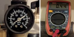

    The fingers may give too little current. A more efficient power source is needed here. I used a regulated power supply with high current efficiency.
  • #84 20335696
    mako122
    Level 12  
    Information for those repairing the tank on their own .
    There are a lot of very cheap tanks on Allegro at the moment. I just bought a tank for PLN 100 just to test the urea pressure sensor. The tank turned out to be in very good condition, although it was dismantled and there is no pump motor in it. Everything else is in great condition!!! I'm just starting to test the urea pressure sensor.

    The guy has a lot of tanks for almost every type of car from the Peugeot group. All for PLN 100!!!
  • #85 20339688
    mako122
    Level 12  
    Pressure sensor test HM8500J SCR Urea Pressure Sensor

    The HM8500J SCR Urea Pressure Sensor is responsible for measuring the pressure of the AdBlue pump.
    Sensor manufacturer website: https://www.ever-smart.com/product/99.html.

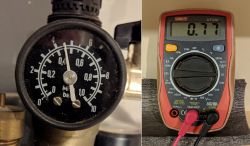
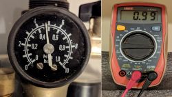
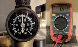
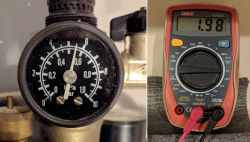
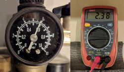
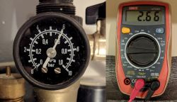
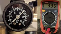
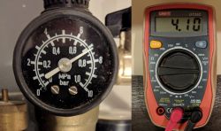
    Earlier in this thread, I did a test of this sensor (see: answer no. 70 of 06 Dec 2022 15:26) but the sensor did not respond to a change in pressure. It turned out to be damaged. I managed to buy a used tank for PLN 100 on Allegro with a working sensor and do some tests. The sensor turned out to be functional. It responds very well to pressure changes. The exact results of the sensor test are presented below:

    PEUGEOT BOXER III - Repair of the AdBlue tank PEUGEOT BOXER III, CITROEN JUMPER

    PEUGEOT BOXER III - Repair of the AdBlue tank PEUGEOT BOXER III, CITROEN JUMPER

    PEUGEOT BOXER III - Repair of the AdBlue tank PEUGEOT BOXER III, CITROEN JUMPER

    PEUGEOT BOXER III - Repair of the AdBlue tank PEUGEOT BOXER III, CITROEN JUMPER

    PEUGEOT BOXER III - Repair of the AdBlue tank PEUGEOT BOXER III, CITROEN JUMPER

    PEUGEOT BOXER III - Repair of the AdBlue tank PEUGEOT BOXER III, CITROEN JUMPER

    PEUGEOT BOXER III - Repair of the AdBlue tank PEUGEOT BOXER III, CITROEN JUMPER

    PEUGEOT BOXER III - Repair of the AdBlue tank PEUGEOT BOXER III, CITROEN JUMPER

    PEUGEOT BOXER III - Repair of the AdBlue tank PEUGEOT BOXER III, CITROEN JUMPER

    PEUGEOT BOXER III - Repair of the AdBlue tank PEUGEOT BOXER III, CITROEN JUMPER

    PEUGEOT BOXER III - Repair of the AdBlue tank PEUGEOT BOXER III, CITROEN JUMPER

    PEUGEOT BOXER III - Repair of the AdBlue tank PEUGEOT BOXER III, CITROEN JUMPER

    PEUGEOT BOXER III - Repair of the AdBlue tank PEUGEOT BOXER III, CITROEN JUMPER


    PEUGEOT BOXER III - Repair of the AdBlue tank PEUGEOT BOXER III, CITROEN JUMPER


    As you can see in the graph, the pressure sensor starts measuring from a pressure of 4.0 bar to about 7.2 bar.
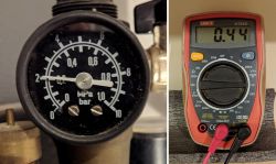
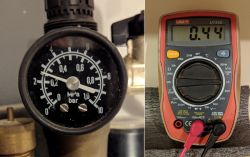
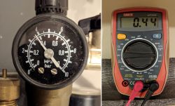
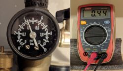
    From atmospheric pressure to 4.0, the output voltage is approximately 0.45 V.
    Normal operation of the pump after initial charging of the accumulator (small urea tank - the size of a glass) is in the range of 4.9 bar to 6.1 bar.
    After reaching the pressure of 6.1, the pump switches off and as successive portions of urea are fed through the urea injector, the pressure drops to 4.9 and at this value the accumulator is recharged.
    The pump works only periodically, its task is to load the urea into the accumulator to a pressure of 6.9 bar.
    The pressure is maintained by a spring-loaded piston which is part of the accumulator.
    The values of voltage and pressure may be slightly different from those given, this is due to the inaccurate measuring devices.

    cdn....
  • #86 20344751
    mako122
    Level 12  
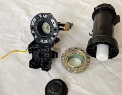
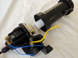
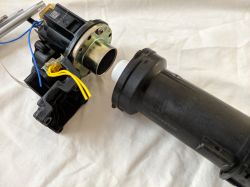
    Urea accumulator - construction and operation:

    PEUGEOT BOXER III - Repair of the AdBlue tank PEUGEOT BOXER III, CITROEN JUMPER PEUGEOT BOXER III - Repair of the AdBlue tank PEUGEOT BOXER III, CITROEN JUMPER

    PEUGEOT BOXER III - Repair of the AdBlue tank PEUGEOT BOXER III, CITROEN JUMPER PEUGEOT BOXER III - Repair of the AdBlue tank PEUGEOT BOXER III, CITROEN JUMPER


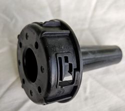
    The photos above show the dry part of the urea battery

    PEUGEOT BOXER III - Repair of the AdBlue tank PEUGEOT BOXER III, CITROEN JUMPER PEUGEOT BOXER III - Repair of the AdBlue tank PEUGEOT BOXER III, CITROEN JUMPER PEUGEOT BOXER III - Repair of the AdBlue tank PEUGEOT BOXER III, CITROEN JUMPER PEUGEOT BOXER III - Repair of the AdBlue tank PEUGEOT BOXER III, CITROEN JUMPER
    PEUGEOT BOXER III - Repair of the AdBlue tank PEUGEOT BOXER III, CITROEN JUMPER PEUGEOT BOXER III - Repair of the AdBlue tank PEUGEOT BOXER III, CITROEN JUMPER PEUGEOT BOXER III - Repair of the AdBlue tank PEUGEOT BOXER III, CITROEN JUMPER PEUGEOT BOXER III - Repair of the AdBlue tank PEUGEOT BOXER III, CITROEN JUMPER PEUGEOT BOXER III - Repair of the AdBlue tank PEUGEOT BOXER III, CITROEN JUMPER


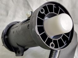
    In the pictures above, the wet part of the urea battery

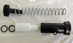
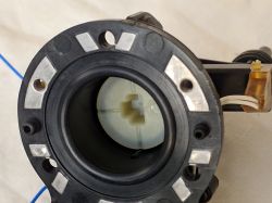
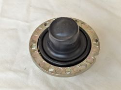
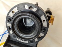
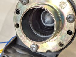
    The urea accumulator consists of two parts, a wet one (a chamber filled with urea under a pressure of 4.9 bar to a maximum of 6.1 bar) and a dry one, which contains a piston pushed with great force by a spring into the wet chamber. There is a rubber sealing cap between these two parts. Its task is to prevent the urea from getting into the space where the spring is located. When charging the battery, the pump pushes the piston back and fills the chamber with urea. After filling the chamber to the pressure of 6.1 bar, the pump stops, the solenoid valve closes, preventing the urea from flowing back to the tank. During subsequent injections of urea, the chamber is gradually emptied. The spring pressing on the piston prevents the pressure drop in the accumulator. Once the battery compartment is empty, it is recharged by the pump and the cycle repeats. When we turn off the car engine so that the urea does not remain under high pressure, the pump will turn on and, working in the opposite direction, pumps the urea back to the main tank.
    To sum up, the accumulator is a large syringe where the piston is not actuated by the force of the finger muscles, but by a spring.
    The spring under the influence of urea pressure shortens thus storing energy which then gives back maintaining the pressure in the accumulator. In fact, the force of this spring is responsible for the subsequent injections!! During subsequent injections, the pump does not work, the energy accumulated in the spring feeds successive portions of urea. The pump works periodically and is used to fill the chamber with urea and compress the spring.

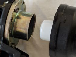
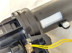
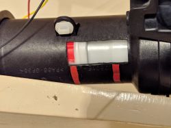
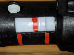
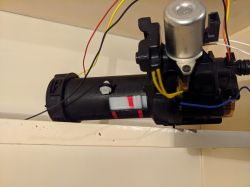
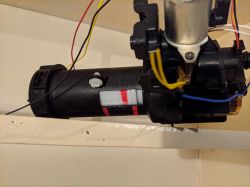
    In order to show the operation of the piston in the battery housing, I made a rectangular inspection hole:


    PEUGEOT BOXER III - Repair of the AdBlue tank PEUGEOT BOXER III, CITROEN JUMPER

    The red markings show the range of movement of the plunger:

    PEUGEOT BOXER III - Repair of the AdBlue tank PEUGEOT BOXER III, CITROEN JUMPER

    Subsequent phases of the piston movement:

    PEUGEOT BOXER III - Repair of the AdBlue tank PEUGEOT BOXER III, CITROEN JUMPER PEUGEOT BOXER III - Repair of the AdBlue tank PEUGEOT BOXER III, CITROEN JUMPER PEUGEOT BOXER III - Repair of the AdBlue tank PEUGEOT BOXER III, CITROEN JUMPER


    Movies
    (the sound in the videos comes from the operation of the installation used for testing) The battery itself works completely silently.


    Urea battery charging phase. In this phase, the pump works and urea is pumped from the main tank to the accumulator chamber. Under the influence of increasing pressure, the piston moves backwards. The spring is compressed, which in this way accumulates the energy needed to work in the injection phase.


    Urea injection phase (accelerated) This phase does not require the AdBlue pump to run. All the energy needed comes from the spring. The tank is not doing anything significant in this phase. The entire injection is managed by the urea injector, which is located outside the tank and is a completely separate device. The electronics of the tank only monitors the urea pressure and on this basis it knows when the battery is empty and the charging phase should be started.


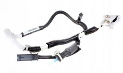
    Urea Injector:

    PEUGEOT BOXER III - Repair of the AdBlue tank PEUGEOT BOXER III, CITROEN JUMPER

    AdBlue line (full-length heated tube) connecting the AdBlue tank to the injector:

    PEUGEOT BOXER III - Repair of the AdBlue tank PEUGEOT BOXER III, CITROEN JUMPER


    cdn....
  • #87 20347648
    st.sitarz
    Level 12  
    Hello !
    I will briefly describe my case with the AdBlue tank Peugeot 5008 II year 2017 engine 2.0 180KM. The car was imported from France in 2001 after over a year of use and over 20,000 km. km started pouring standard errors. After deleting the errors, the car sometimes drove even 300 - 500 km and there was no error, then suddenly there was a fault with the AdBlue system, then the check engine light, then the countdown. It happened that the error spontaneously disappeared, and the lights went out, but over time, unfortunately, the damage made itself felt more and more often and deleting the errors and driving became a nuisance.
    After performing the performance test of the system (on the unscrewed injection), it turned out that the urea is beautifully sprayed and passes the test with the information: no defect, but does not end the tank heating test positively. That gave me some clue. Thanks to the knowledge that my friend mako122 gave us and the other cases described here, I started looking for a fault, the only one I found was a damaged SMD thermistor which is placed on the hob (yellow wires). Incorrect resistance (approx. 700 Ohm at 7 degrees C) meant that the tank did not pass the efficiency test and was disconnected. When the engine warmed up and there was a need to inject AdBlue into the exhaust system, it did not occur, which generated errors. I temporarily put a resistor in series with me in the "yellow" circuit corresponding to the temperature of 7 degrees C and the system started after traveling about 1000 km, everything works as it should. It is confirmed that this thermistor is incorrectly placed and its defect disqualifies even a good tank for further operation. With the system working properly along the route, after stopping and switching off the ignition, the pump "retracts" the urea from the lines to the tank (audible pump operation) as described above.
    I am now looking for a used tank in which, for example, the electronic part or the pump is damaged. For now, I'm at the stage of buying a functional tank without electronics and this should settle the matter definitively.
    I wrote a bit, but my colleague mako122 inspired me to act, and I would like to point out that I am just an automotive hobbyist. If I have described something wrong, please let me know.
  • #88 20357739
    dejaq
    Level 11  
    Welcome back.
    For the record, my fix was to replace the heater sensor with a 10k resistor.
    I drove a bit (about a month/1000km) including 2 days at temperatures around -12. No mistakes. Which leads me to the conclusion that the sensor on the heater only plays a protective role. Otherwise, the program should recognize that something is wrong.

    I have 2 more observations.
    @lukas_sz asked what it means in the digbox that "urea pump indicator module turned off empty". I noticed that it is "empty" if the tank was not pressurized when the ignition/power was turned off, and it changes to "full" if the tank was at operating pressure when the ignition/power was turned off.

    It is not worth 100% believing in the result of the heating circuit test in DiagBox. i.e. Positive as much as possible, negative not entirely. It turns out that if the battery is not in good enough condition, this test may fail even with efficient heating circuits. The test is carried out with the engine off. It seems to me that despite the fact that the diagbox talks to the controller, the power is cut off somewhere due to energy saving and the test comes out negative. However, if you do it immediately after turning off (after a long work), it comes out positive.
  • #89 20369539
    telefonodmarcina
    Level 2  
    Hello,
    Has anyone encountered such a case that the low pressure error P20E8 "shows" only after the engine reaches a coolant temperature of 90-91 degrees?
    My case is that I can cover X kilometers in short trips and if the engine temperature does not reach 90 degrees (I check via the obd connector and the phone application showing the engine temperature) the error will not occur. But as soon as the engine temperature reaches 90 - 91 degrees, there will be an engine error and then service and urea.
    Before I start in the "dark" (in the dark, i.e. first plugs, wires ... etc.) to look for the cause, maybe this symptom someone of you knows and will tell you why, after warming up to 90 degrees, the computer diagnoses the Adblue error.
  • #90 20369641
    ZlPu
    Level 2  
    This is normal, the AdBlue injection is only released at approx. 90°C TCO. When the engine is cold, the system waits. Only then does the diagnostic become active and monitor the system. The pump is inactive below 90°.

Topic summary

The discussion revolves around the repair and troubleshooting of the AdBlue tank in PEUGEOT BOXER III and CITROEN JUMPER vehicles. Users share their experiences with common issues such as low pressure errors (P20E8), sensor malfunctions, and the need for system resets. Key solutions include replacing or bypassing faulty sensors, particularly the heating plate temperature sensor, and ensuring proper electrical connections. Users emphasize the importance of checking for urea crystallization and leaks, as well as the necessity of clearing error codes after repairs. The conversation also touches on the complexities of the AdBlue system's electronics and the potential for DIY repairs using resistors to simulate sensor readings.
Summary generated by the language model.
ADVERTISEMENT