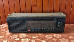
logo elektroda
logo elektroda
X
logo elektroda

Unitra Taraban 2 - DMP-602 - interior photo gallery, schematic diagram

p.kaczmarek2 4827 14
ADVERTISEMENT
Treść została przetłumaczona polish » english Zobacz oryginalną wersję tematu
  • Unitra Taraban 2 - DMP-602 - interior photo gallery, schematic diagram .
    Hello my dears. .
    I would like to invite you to a short teardown of an old Polish Taraban 2 radio, which unfortunately came to me already in a rather bad condition. As standard, I will present here detailed photos from the inside and then post the schematic and documentation.

    Taraban 2 - DMP-602 .
    Taraban 2 receives long wave, medium wave, short wave and UKF. The AM intermediate frequency is 465kHz and FM is 10.7MHz. For more details, I refer you to the manual:
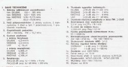
    Unitra Taraban 2 - DMP-602 - interior photo gallery, schematic diagram .
    Which connector is which, button roles, etc:
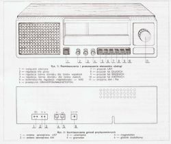
    Unitra Taraban 2 - DMP-602 - interior photo gallery, schematic diagram .
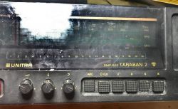
    Photo of the front, the scale is illuminated using ordinary 6.3V/0.2A bulbs, which we will see soon.
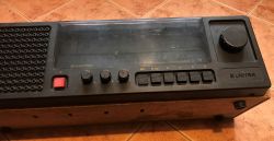
    Unitra Taraban 2 - DMP-602 - interior photo gallery, schematic diagram .
    Unitra Taraban 2 - DMP-602 - interior photo gallery, schematic diagram .
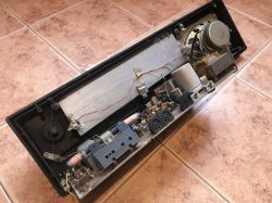
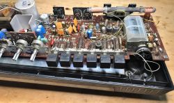
    The receiver, unfortunately, I have already salvaged in very poor condition. Both the casing and the interior:
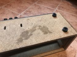
    Unitra Taraban 2 - DMP-602 - interior photo gallery, schematic diagram Unitra Taraban 2 - DMP-602 - interior photo gallery, schematic diagram Unitra Taraban 2 - DMP-602 - interior photo gallery, schematic diagram Unitra Taraban 2 - DMP-602 - interior photo gallery, schematic diagram .
    The back plate is missing, the electronics can simply be removed along with the front:
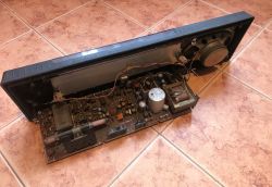
    Unitra Taraban 2 - DMP-602 - interior photo gallery, schematic diagram .
    Antenna connector also torn out:
    Unitra Taraban 2 - DMP-602 - interior photo gallery, schematic diagram .
    Unitra Taraban 2 - DMP-602 - interior photo gallery, schematic diagram .
    There is a spatial arrangement of the elements in the documentation:
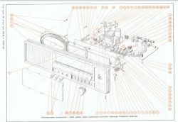
    Unitra Taraban 2 - DMP-602 - interior photo gallery, schematic diagram .
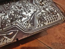
    PCB tracks. Some of the solders look poor:
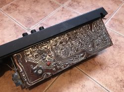
    Unitra Taraban 2 - DMP-602 - interior photo gallery, schematic diagram Unitra Taraban 2 - DMP-602 - interior photo gallery, schematic diagram .
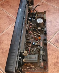
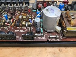
    Time for clearer pictures of the board. I had to at least pre-clean it, the layer of dirt is extremely thick.
    Here you can see, among other things, the fuses, the 1PM05 rectifier bridge and the UL1211 IC:
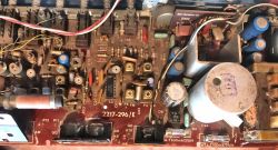
    Unitra Taraban 2 - DMP-602 - interior photo gallery, schematic diagram .
    Unitra Taraban 2 - DMP-602 - interior photo gallery, schematic diagram .
    Unitra Taraban 2 - DMP-602 - interior photo gallery, schematic diagram .
    Unitra Taraban 2 - DMP-602 - interior photo gallery, schematic diagram .
    We even have the board voltages listed in the service manual:
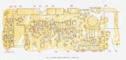
    Unitra Taraban 2 - DMP-602 - interior photo gallery, schematic diagram .
    Rails with potentiometers, switches:
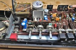
    Unitra Taraban 2 - DMP-602 - interior photo gallery, schematic diagram .
    Unitra Taraban 2 - DMP-602 - interior photo gallery, schematic diagram .
    The mechanism for switching ranges is shown well in the manual:
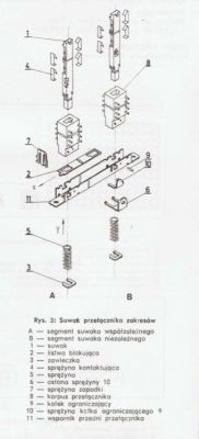
    Unitra Taraban 2 - DMP-602 - interior photo gallery, schematic diagram
    Tonsil speaker GD10-16/5/2 5W 4Ω Made In Poland:
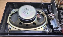
    Unitra Taraban 2 - DMP-602 - interior photo gallery, schematic diagram .
    The second IC inside is a UL1481 CEMI, together with a heatsink:
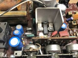
    Unitra Taraban 2 - DMP-602 - interior photo gallery, schematic diagram .
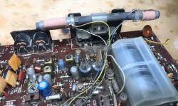
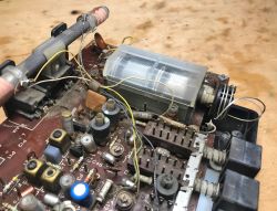
    Ferrite antenna, tuning capacitor:
    Unitra Taraban 2 - DMP-602 - interior photo gallery, schematic diagram .
    Unitra Taraban 2 - DMP-602 - interior photo gallery, schematic diagram .
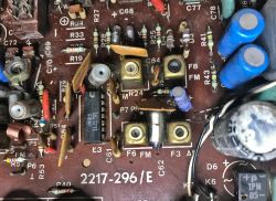
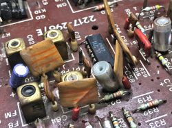
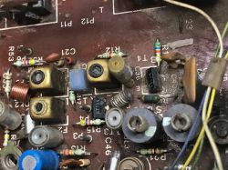
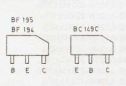
    Transistors w.c. BF194 in the characteristic housing of the time:
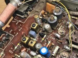
    Unitra Taraban 2 - DMP-602 - interior photo gallery, schematic diagram Unitra Taraban 2 - DMP-602 - interior photo gallery, schematic diagram .
    Unitra Taraban 2 - DMP-602 - interior photo gallery, schematic diagram
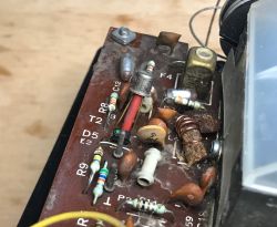
    BF215 transistor and a characteristic capacitive diode (warp) with a green dot, probably BB105G (yes, I checked on the schematic).
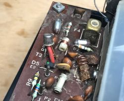
    Unitra Taraban 2 - DMP-602 - interior photo gallery, schematic diagram Unitra Taraban 2 - DMP-602 - interior photo gallery, schematic diagram .
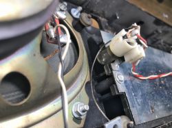
    The aforementioned backlighting - the bulb:
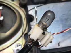
    Unitra Taraban 2 - DMP-602 - interior photo gallery, schematic diagram
    Unitra Taraban 2 - DMP-602 - interior photo gallery, schematic diagram .
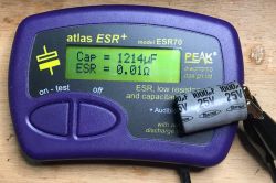
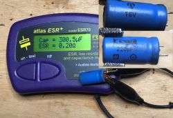
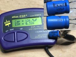
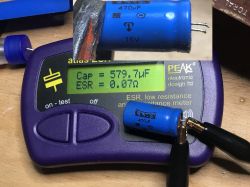
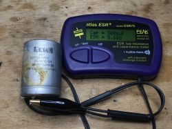
    Out of sheer curiosity I decided to check the capacitance and ESR status of the ELWA electrolytic capacitors from inside this radio. For this I used a rather expensive ESR70 meter that I have tested and know does not overestimate the measurements. Would the capacitors be in poor condition or also perhaps their capacity has increased? Let's see:
    Unitra Taraban 2 - DMP-602 - interior photo gallery, schematic diagram Unitra Taraban 2 - DMP-602 - interior photo gallery, schematic diagram feUnitra Taraban 2 - DMP-602 - interior photo gallery, schematic diagram Unitra Taraban 2 - DMP-602 - interior photo gallery, schematic diagram Unitra Taraban 2 - DMP-602 - interior photo gallery, schematic diagram Unitra Taraban 2 - DMP-602 - interior photo gallery, schematic diagram
    Capacities are consistently higher than nominal, but overall it is not so bad, although I refer to the ESR tables to assess specific results. The results are repeated for a further 100uF/220uF not included in the images.

    Service manual (in Polish) .
    For this radio, detailed documentation and instructions in Polish are available online. I don't see the need to over-quote it here, I'm simply attaching the PDF for download (schematic also inside):
    Taraban_2_...MP-602.pdf Download (14.64 MB) .

    Summary .
    A radio in much worse condition than the ones I usually find. I don't know how much time it has spent in the air and rain. I know you can get one very cheaply in good condition, but it's not about just buying. Maybe if I fix the solders I can get something going with it. At least the head doesn't look like it's been tampered with, so it's better than if it had been completely ripped out due to some failed attempt at UKF tuning.
    That's it for now, perhaps I'll come back to this receiver in another topic in the form of commissioning+tuning.

    Cool? Ranking DIY
    Helpful post? Buy me a coffee.
    About Author
    p.kaczmarek2
    Moderator Smart Home
    Offline 
    p.kaczmarek2 wrote 11826 posts with rating 9927, helped 564 times. Been with us since 2014 year.
  • ADVERTISEMENT
  • #2 19789615
    Anonymous
    Level 1  
  • #3 19789656
    szeryf3
    Level 29  
    I see you are starting to collect old receivers.
    Repairing a pcb is sometimes less of a problem than repairing a box.
    Too bad you don't have the backs because you would be able to determine the year of manufacture.
  • ADVERTISEMENT
  • #4 19789755
    yogi009
    Level 43  
    parabuch wrote:
    I am always impressed by these service manuals for old equipment. it would be useful to have one for modern equipment


    I had the same thought, everything laid out as if on the palm of my hand.
  • #5 19789856
    bsw
    Level 21  
    I have a radio like this. It has been in continuous function in the kitchen for over 20 years (when it was tuned) playing sometimes several hours a day.
    From failures:
    - scale bulbs burnt out - replaced,
    - creaking potentiometers - KC Kontakt helped,
    - a non-contacting mains switch - the plastic of the case was split - I replaced it with another, contemporary one.
    And that's it.
    The receiver has a bluetooth mod connected to the tape deck socket, so it also makes a wireless speaker :-) .
    To sum up:
    Good product with interesting design, excellent sound. Fits perfectly with the fridge on which it stands :-) .
    I can't imagine replacing it with a typical kitchen radio alarm clock.
  • ADVERTISEMENT
  • #6 19790056
    ArturAVS
    Moderator
    I had another version with a round speaker, after a few years I converted the amplifier itself to stereo. Together with the MK232P also converted to stereo (a'la deck) it surprised the neighbours who had Unitra or Radmor tower sets with its quality.
    parabuch wrote:
    I am always impressed by these service manuals for old equipment
    .
    When I was already at RTV technical school, there was a Unitra-Serwis shop a few streets away, you could probably buy all the service manuals for the equipment produced in those years. Towards the end, when Unitra was liquidated, it was possible to buy various modules and components very cheaply. I managed to buy a complete motherboard for an Elwro 800 Junior as well as spare speakers for a m/n Taraban.
    parabuch wrote:
    they would be useful for modern
    .
    There are manuals for modern equipment too, although only in electronic form, and for really new designs they cost some $$. Anyway, modern equipment for general use is not considered serviceable, it breaks down you have to dispose of it and buy a new one.
  • #7 19790347
    mrrudzin
    Level 39  
    ArturAVS wrote:
    .
    There are manuals for modern equipment too although only in electronic form and for really new designs they cost some $$. Anyway modern equipment for general use is not considered serviceable, it breaks down then you have to dispose of it and buy a new one.


    Unfortunately nowadays, if anything, whole modules are replaced and manufacturers do everything to make repairs as difficult as possible.
    In equipment manufactured some time ago, the ubiquitous latches and glued-in cases were annoying. Recently I saw somewhere an attempt to repair some xbox - not only that you can not even find datasheets of chips (the manufacturer orders a whole batch only for his devices), in addition, for example, the chip that controls the inverter is programmable - so if by some miracle you get somewhere a replacement will not work anyway.
  • #8 19790410
    alek25
    Level 25  
    szeryf3 wrote:
    I see you are starting to collect old receivers.
    Repairing a pcb is sometimes less of a problem than repairing a box.
    Too bad you don't have the backs because you would be able to determine the year of manufacture.
    .

    On the large electrolyte you have a production date of 0481 - April 1981, this is more or less also the production date of this receiver, with a deviation of plus a quarter
  • ADVERTISEMENT
  • #9 19791469
    kris8888
    Level 39  
    p.kaczmarek2 wrote:
    .
    Out of sheer curiosity I decided to check the capacitance and ESR status of the ELWA electrolytic capacitors inside this radio.

    Such a measurement is best carried out after such a capacitor has been connected for at least several minutes to a voltage close to its rated voltage and then discharged to zero. Especially if the capacitors have been unused for years and the radio itself has been stored in extreme conditions. Measurement results can vary quite a lot.
  • #10 19791509
    pawelr98
    Level 39  
    The head is identical to many other Dior designs.
    In my 1:1 Duet it's the same, even the layout of the components on the laminate is similar.

    Tuning, apart from the L3 coil which is cumbersome to tune, is not a problem.
    You have to bend these coils a bit in all directions until you have the correct tuning range.

    As for the radio itself, as always it was a combination, not doing the right thing.
    UL1481 and 18V power supply, above 15V no protection in this power amplifier works anymore.
    There is no voltage stabilisation, so you have to be careful what the mains voltage is, as the UL1481 can withstand up to 20V maximum.

    I didn't combine with these carcasses (2xUL1481), I just put TDA2009, in this radio you could also put something more tolerable with parameters and safer.
  • #11 19791511
    rnb_bolii
    Level 39  
    Even so, ELWA used to make good capacitors. So much time, and the capacitance holds BA! with a hook. In those days ESR was not as important as it is today.
  • #12 19797335
    Grzegorz740
    Level 37  
    I too have such a radio receiver only it is a Taraban 3 R-510. The difference between the one in the article and the one I have is only in the front casing, there is a different scale and there are different switch covers. Electronically it is the same.

    And the story of my Taraban is that while going to my buddy's place I found it near a dumpster. So I took an interest in it.
    I replaced the bulbs in it from the scale illumination and also replaced the electrolytic capacitors because there was a hum, after replacing them the hum stopped. And, of course, I had to tune the UKF.

    I have to say, it has a very nice sound - not like those plastic market radios.

    It would be nice if you refurbished it, tuned it. Well worth it.
  • #13 19797800
    audiofil
    Level 13  
    rnb_bolii wrote:
    Although, ELWA used to make good capacitors. So much time, and the capacitance holds BA! with a hook. In those days ESR was not as important as it is today.
    . Except for the small ones so up to 10u 22u These are generally always replaceable.
  • #14 19798661
    rnb_bolii
    Level 39  
    audiofil wrote:
    rnb_bolii wrote:
    Although, ELWA used to make good capacitors. So much time and the capacitance holds BA! with a hook. In those days ESR was not as important as it is today.
    . Except for the small ones so up to 10u 22u These are generally always replaceable.
    .

    That's right. They can even short-circuit the inside and mess with the circuits.
  • #15 19820055
    kill14
    Level 2  
    good radio still plays today

Topic summary

The discussion centers on the teardown and restoration of the Polish Unitra Taraban 2 radio (model DMP-602), which covers long wave, medium wave, short wave, and FM (UKF) bands with intermediate frequencies of 465 kHz for AM and 10.7 MHz for FM. Detailed interior photos, schematic diagrams, and documentation were shared. Participants noted the quality and durability of the radio, highlighting common maintenance issues such as burnt-out scale bulbs, creaking potentiometers, and plastic case damage. Some users replaced electrolytic capacitors to eliminate hum and tuned the UKF band for improved reception. The original UL1481 amplifier IC and 18V power supply lack voltage stabilization and protection above 15V, prompting suggestions to replace the amplifier with more robust alternatives like the TDA2009. The radio’s design and component layout resemble other Dior models, with tuning challenges mainly involving the L3 coil. The discussion also touched on the difficulty of repairing modern electronics due to proprietary components and lack of service manuals, contrasting with the serviceability of vintage equipment like the Taraban series. A related model, Taraban 3 R-510, was mentioned as electronically similar but differing in front panel design. Overall, the Taraban radios are praised for their sound quality, robust construction, and potential for refurbishment and modernization, including Bluetooth integration.
Summary generated by the language model.
ADVERTISEMENT