logo elektroda
logo elektroda
X
logo elektroda

Radio from the kitchen of communist Poland - Unitra, Ludwik DMT-408 - gallery, interior, diagram

p.kaczmarek2 3981 31
ADVERTISEMENT
Treść została przetłumaczona polish » english Zobacz oryginalną wersję tematu
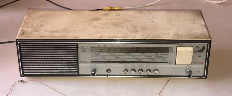
  • Old Polish Ludwik radio receiver from the 70s with a large rocker On/Off button on the right side of the front panel. .

    I would like to invite you to another topic about an old Polish radio receiver, this time about a Ludwik from the 1970s, characterised by a large rocker On/Off button on the right side of the front of the case. This receiver allows you to listen to four ranges, standard long wave, medium wave, short wave and ultra short wave, whereby to listen to something in our time you would have to tune out the UKF, but to start with a look at the casing:
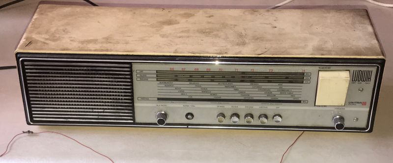
    Vintage Polish radio receiver Unitra Ludwik from the 70s. .
    Old Polish radio receiver Ludwik with a large On/Off button on the right side.

    On the front, in addition to the range selector and volume control, we also have a tone knob and the option to switch to the tape deck connector.
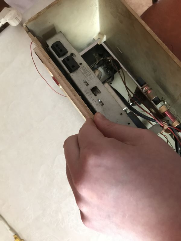
    Hand holding an old radio receiver with a visible back panel. .

    On the back we have a cassette connector, a connector for the aerial, in my case unfortunately the back cover is missing.
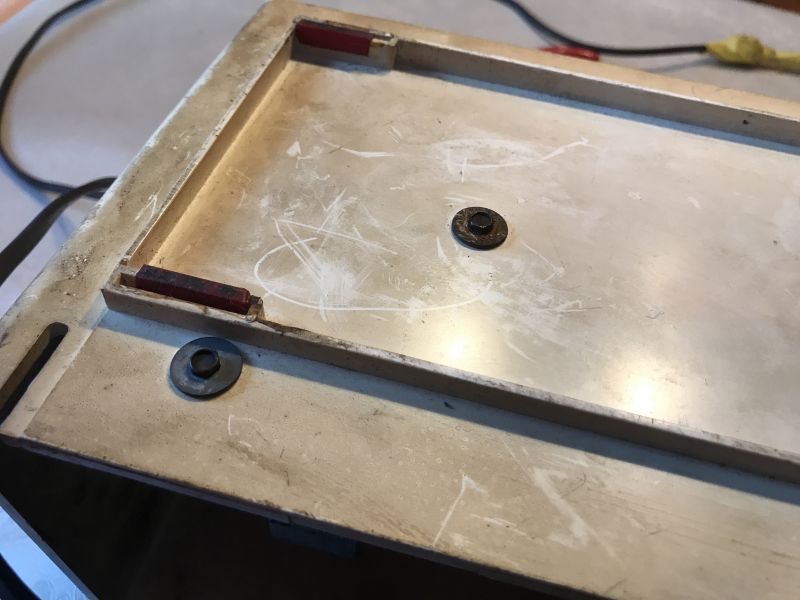
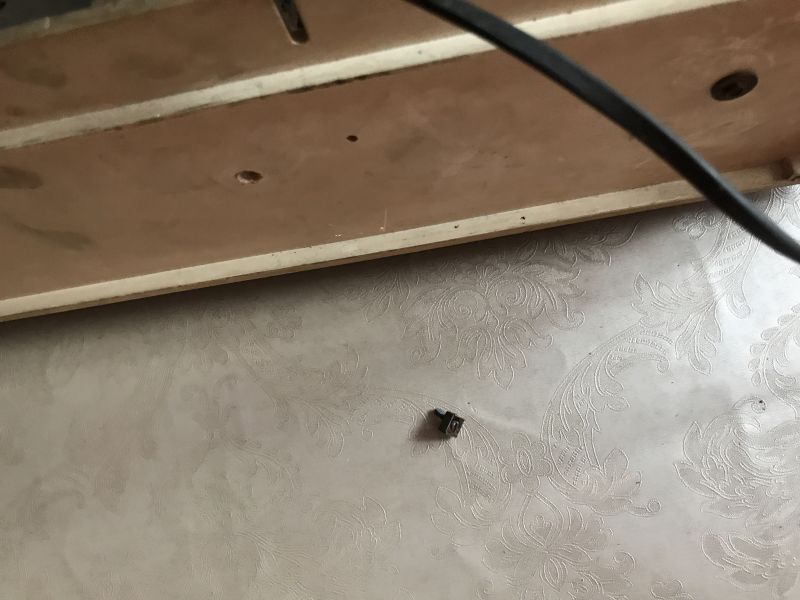
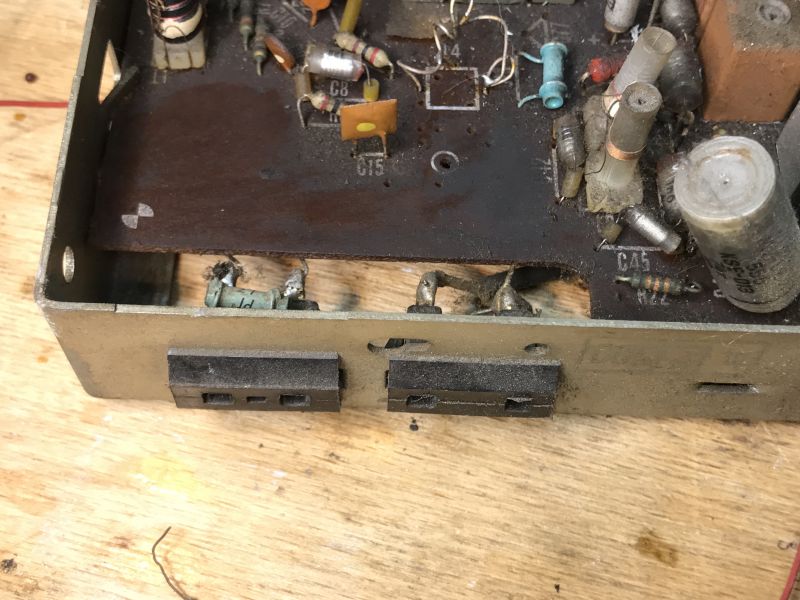
    Bottom part of an old Polish radio receiver's casing without the back panel. Bottom part of the old Ludwik radio receiver from the 70s, with an inner component placed on the surface. .

    After freeing the PCB and separately the mains transformer, the front with the electronics can be slid out.
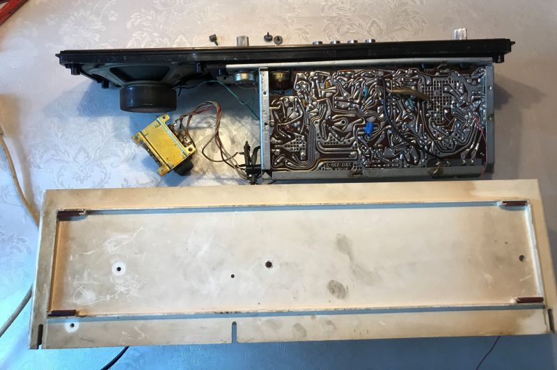
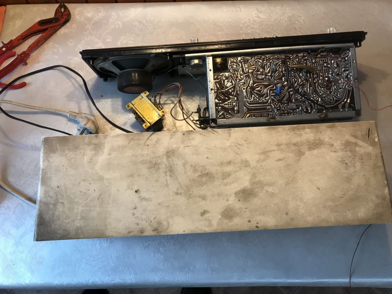
    Disassembled Ludwik radio from the 70s with visible PCB. View of a disassembled 1970s Ludwik radio receiver with visible electronics and speaker.

    The plate is characteristic of the time, single layer, the tracks still guided by hand:
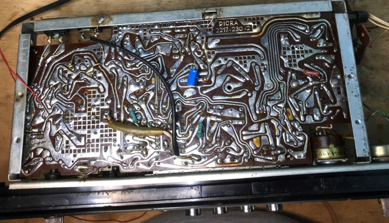
    View of the underside of the PCB of an old Ludwik radio from the 70s. .

    These individual components mounted on the underside are, I don't know at the moment whether this is the user's invention or whether it was manufactured as such?
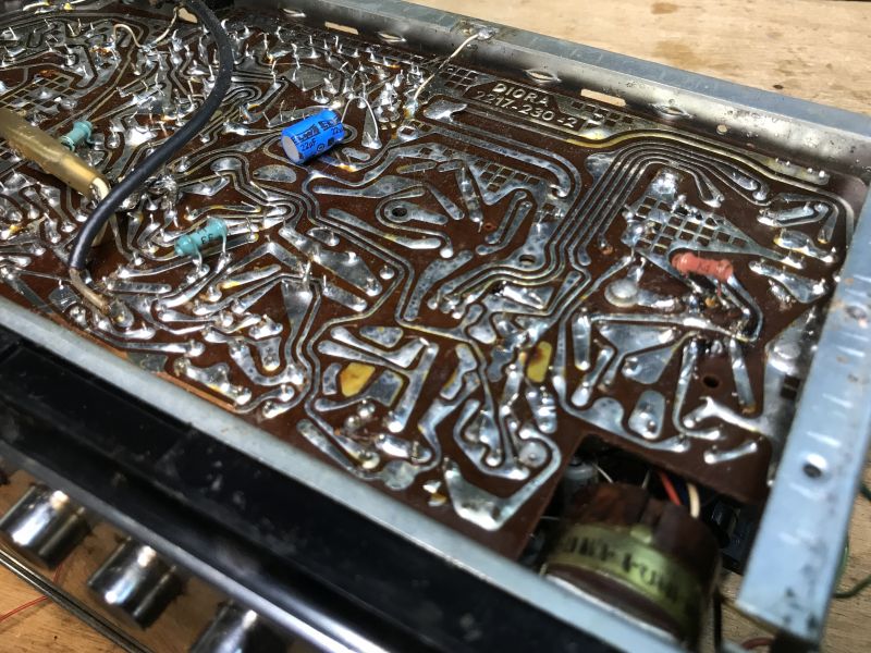
    Close-up of a circuit board from an old radio receiver with visible electronic components and traces.

    The transformer is an ordinary 50Hz mains transformer, Unitra Zatra:
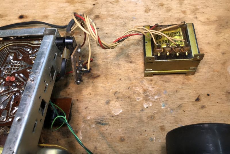
    Internal components of an old Polish Ludwik radio receiver, including a Unitra Zatra transformer and a circuit board. .

    The ferrite antenna is conspicuous inside, and there are traces of tampering:
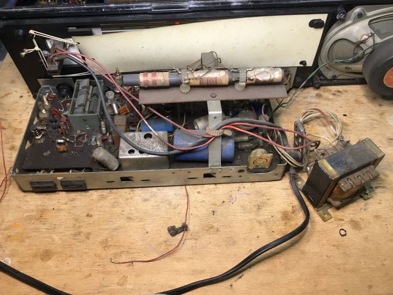
    Dismantled Unitra Ludwik radio receiver from the 1970s with visible electronic components.

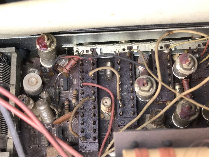
    Here you can see the adjustable capacitor, it is the one that implements the tuning by changing the capacitance.
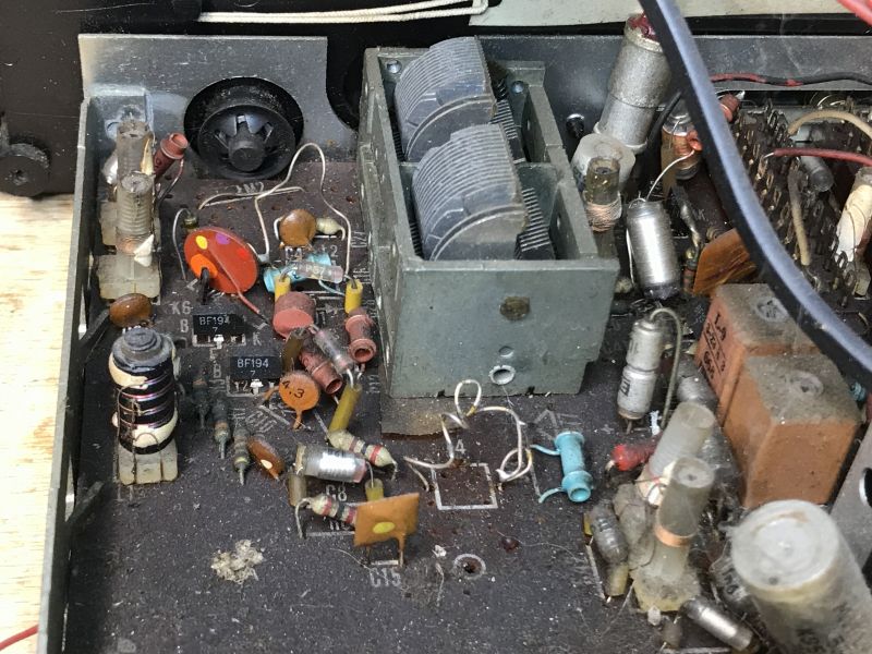
    Interior of a 1970s Unitra radio receiver, showing electronic components, including BF194 transistors and a capacitor.

    Someone must have made an attempt at tuning, with better or worse results.
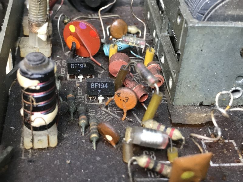
    Close-up view of internal components of an old Polish radio receiver.

    The photo above shows two low-power, high-frequency BF194 silicon transistors typical of the time:
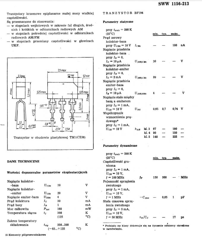
    Technical diagram of the BF194 transistor. .

    Miflex capacitor, with the results of someone else's games in the background:
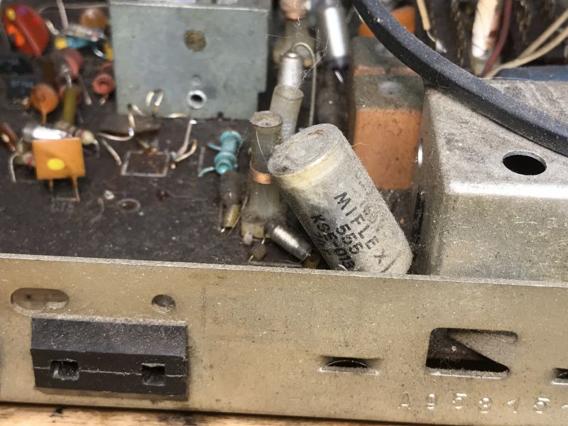
    Close-up photo of the interior of an old radio receiver showing a Miflex capacitor and other electronic components.

    Coupled Isostat switches:

    Close-up of the interior of a 1970s radio with a printed circuit board and electronic components.

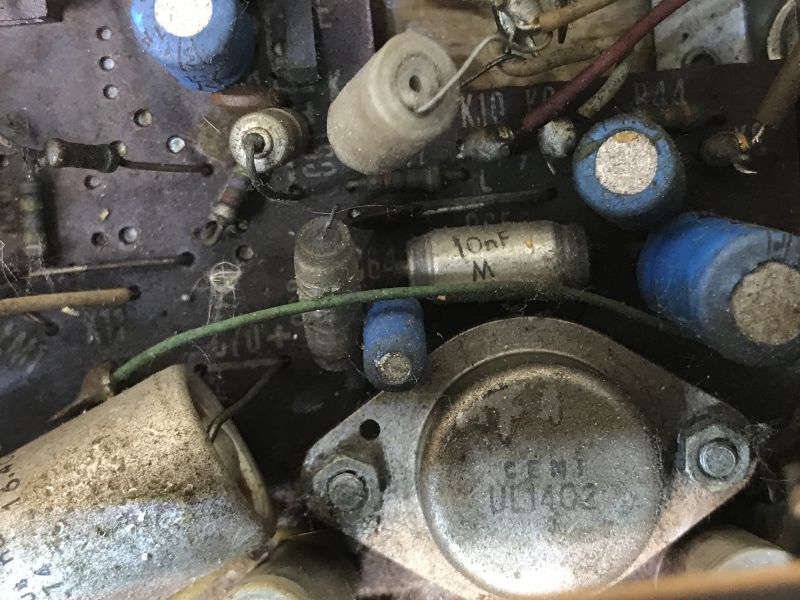
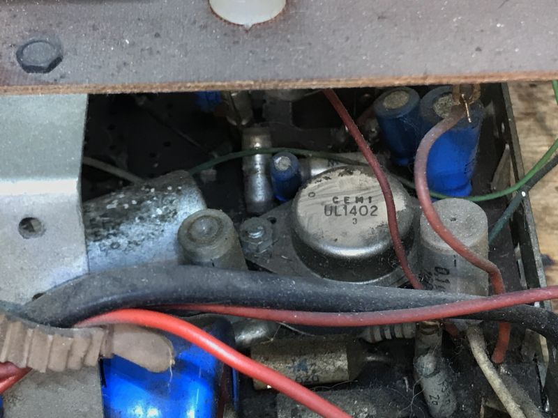
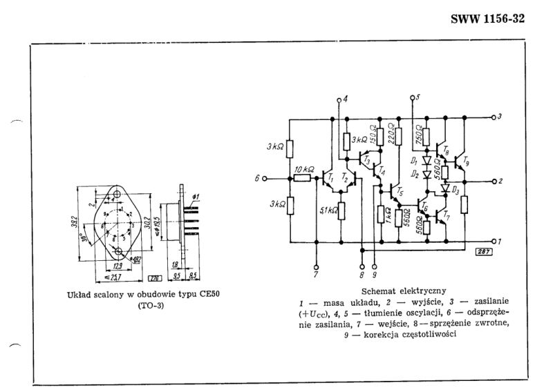
    Below the UL1402 circuit:

    Circuit board of a Ludwik radio with electronic components, including the UL1402 chip .
    Interior view of an old Polish Unitra radio with the CEMI UL1402 amplifier visible. .

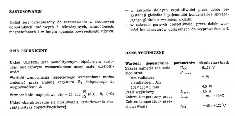
    The UL1402 is a low power amplifier:

    Schematic of an integrated circuit in a CE50 (TO-3) package for a 1970s Unitra Ludwik radio. Technical specification of the UL1402L used in radio and television receivers. .

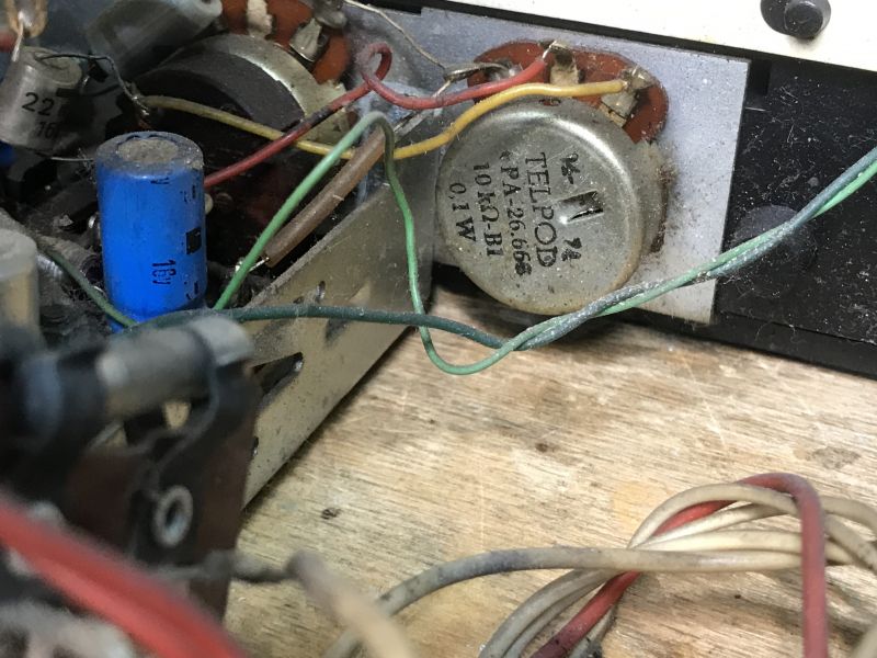
    Telpod 10 kΩ 0.1 W potentiometer:

    Close-up of Telpod potentiometer and internal electronics of an old radio.

    Below, a speaker with the proud inscription Unitra - Made in Poland:
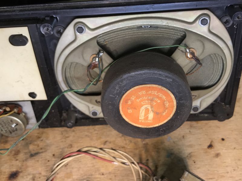
    Interior of an old Polish Ludwik radio receiver with a Unitra speaker. .

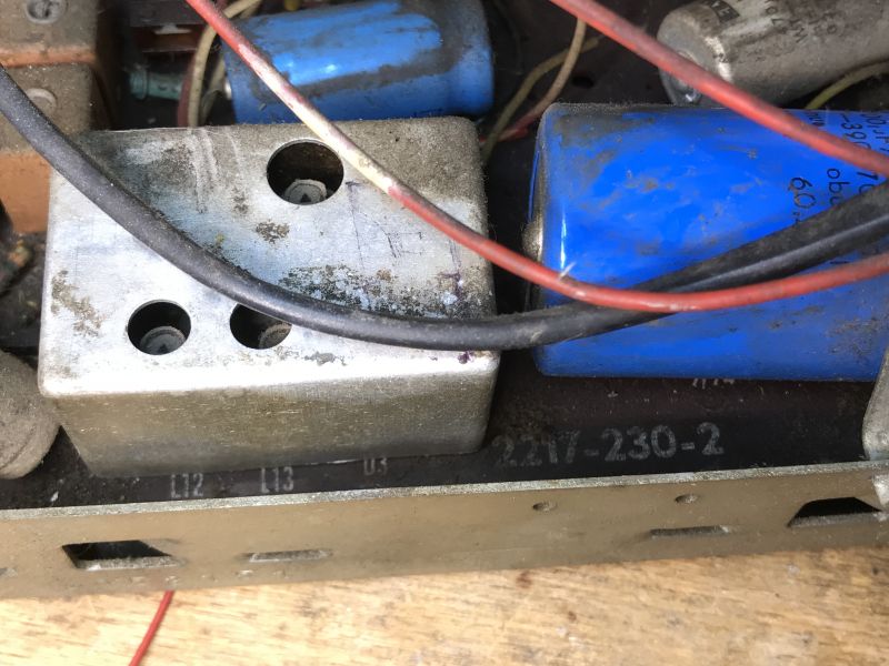
    Shielded part of the circuit:

    Close-up of the interior of an old radio receiver with electronic components. .

    And the connectors:

    Interior view of an old radio receiver with electronic components on a PCB. .

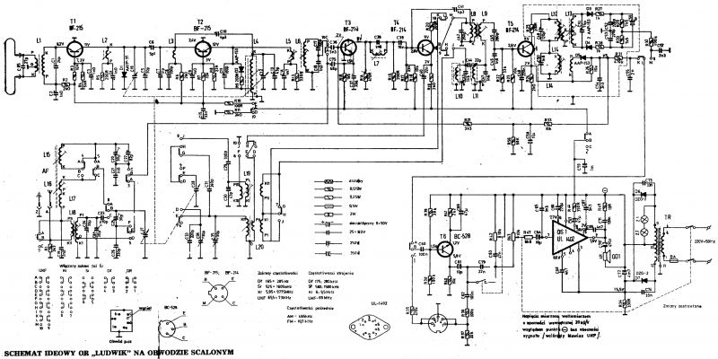
    Finally, a diagram:

    Block diagram of the old Unitra Ludwik DMT-408 radio. .

    The diagram above shows the Ludwig DMT-408 (1974), where the m.c. amplifier is based on the UL1402. There was also an earlier version, the DMT-405, where this was implemented on transistors (1972).

    Summary .
    It's a wonder I didn't know of the existence of this Unitra receiver before. Its unusual style really catches the eye. I wonder what it looked like in its heyday, in its "natural" environment. I simply have no way of remembering it myself, I can only know it from stories. It's a pity that it has already been hit without the back panel. From what I've seen in pictures online, this panel is also pure retro.
    Does anyone have this type of receiver in their collection as well? Feel free to comment and post photos of your specimens.

    Cool? Ranking DIY
    Helpful post? Buy me a coffee.
    About Author
    p.kaczmarek2
    Moderator Smart Home
    Offline 
    p.kaczmarek2 wrote 11914 posts with rating 9980, helped 571 times. Been with us since 2014 year.
  • ADVERTISEMENT
  • #2 20728980
    LA72
    Level 41  
    A fine old piece of equipment.
    I see someone has been tinkering with it before.
  • #3 20729050
    Q-mac
    Level 27  
    Whether it's so noble I don't know. It looks like a "family" to Adam and Gong. Of which I would definitely prefer the aforementioned two.
  • ADVERTISEMENT
  • #4 20729130
    puchalak
    Level 17  
    I hope that the author and the administrator will forgive me a bit of offtopic, but the topic brings together lovers of such radios, so the soonest someone will be interested here.
    Two radios of a similar type, although more modern - Śnieżnik r502 and Taraban 3 - are available for free. Most probably working and probably even tuned. Condition - personal collection in Krakow near Rybitw. Details on PW.
  • #5 20729225
    szeryf3
    Level 29  
    @p.kaczmarek2 a few radios of this type have passed through my life, but I haven't seen this one yet.
    Is the case wooden or bakielite?
    If wooden then there is no veneer on it.
    The unit, or air capacitor, is a little small in size for those years.
    Don't be surprised if someone has already been messing with it, as the radio went through the 70s and then the 90s in which time everyone tuned to the western band.
  • #6 20729445
    Mateusz_konstruktor
    Level 36  
    p.kaczmarek2 wrote:
    Hand holding an old radio receiver with a visible back panel. .

    On the back we have a tape deck connector, a connector for the aerial, in my case unfortunately the back cover is missing.
    .
    Both of these connectors are used to connect antennas.

    I am posting a photo, from the first post, with the connector used to connect the tape recorder marked with a red border.

    Radio from the kitchen of communist Poland - Unitra, Ludwik DMT-408 - gallery, interior, diagram .
  • #7 20729460
    kris8888
    Level 39  
    p.kaczmarek2 wrote:
    These individual components mounted on the underside are, I don't know at the moment whether this is already the user's invention or whether it was manufactured as such?
    .
    These may have already been factory "tweaks". Well maybe apart from that capacitor connected to the UL1402 legs. The UL1402 itself looks like it has probably also already been replaced looking at the burn marks on the laminate and the quality of the solder. These UL1402, like the UL1403 and UL1405, were unfortunately not very durable. Despite the robust housing.
  • ADVERTISEMENT
  • #8 20729592
    acctr
    Level 38  
    You can see by the design that this is quite a vintage receiver, but complete and without significant damage. Something between the older tube ones from the 1960s and the newer ones from the late 1980s.
    It's had a bit of rummaging but that's unlikely to be a problem.
    Once cleaned and tuned, the equipment could still work, especially as it has interesting ranges and not just FM alone.

    The electronics are worthy of note. A complete AM/FM multi-band radio realised de facto on 4 transistors - amplifier, heterodyne, mixer.
    Nowadays it's a single chip with or without passive elements.
    Helpful post? Buy me a coffee.
  • #9 20729630
    kris8888
    Level 39  
    It is probably no longer worth resuscitating this unit. The casing is plastic, of poor quality and in very poor condition. The radio itself has rather low sensitivity and, above all, poor FM selectivity. The reception quality can be very disappointing, even after correct tuning. In addition, the loudspeaker probably has a hole in the upper part of the diaphragm.
    The best thing to do is to keep it for parts, or, if you happen to find a better model from Dzierżoniów, but with, for example, a burnt UL1402, you can make one nice and sound piece out of two. Unfortunately, a lot of these are now ending up in rubbish heaps.
    Apart from that, there is nothing peculiar there in terms of circuit solutions, except maybe for the fact that the whole radio circuit is based on transistors only, and the power amplifier on the less popular UL1402.
  • ADVERTISEMENT
  • #10 20729705
    szeryf3
    Level 29  
    @p.kaczmarek2 the backs I used to make up, but it is labour intensive and tedious work, but it was worth it.
  • #11 20729731
    klm787
    Level 36  
    kris8888 wrote:
    Other than that, there is nothing peculiar there in terms of layout solutions
    .
    Well.
    Because most of these types of radio receivers from "those days" were made on principle in this respect:
    Copy, paste.

    Well, maybe some insignificant changes in the form of changing capacitance, or resistance of passive elements.
  • #12 20729780
    pawelr98
    Level 39  
    acctr wrote:
    .
    Once cleaned and tuned, the equipment can still function, especially as it has interesting ranges and not just FM alone.
    .
    The fact that the ranges are there is unlikely to help, as selectivity on the shortwave range is very poor for this type of radio. In the Tambourine there were 4 p.h. transistors simultaneously working in the AM path and it was poor. Here there are 3, so further cuts were made in an already budget design derived from the Jubilat. The rest of the circuit is identical.

    A well-tuned FM track will have OK selectivity, no problem with station overlap or other such issues. The bigger problem will be that wicked power amplifier.

    As for the mods someone has been sporting here.
    This is a design analogous to the Jubilat/Tambourine and a couple of others.
    If you look closely, the L4 coil should have a metal shield, you can see from underneath that it used to be soldered in. There used to be a carcass sitting there, where presumably a previous 'rummager' came across the merry work of the people at Dior, who decided to deviate from the original Jubilat specification and gave 2.5 coils instead of 3.5.
    Hence, probably this coil and its carcass were replaced by some piece of wire that was supposed to be an air coil. This is probably even the original wire that sat on the casing from the factory.

    And all this is because decades earlier, someone came up with the idea of not adding a coil of wire to the casing and so Diora merrily released successive radios with this "patent".
    If this additional coil had been present, the radio would have tuned normally.
    But now you have a mess, because the tapping instead of halfway falls somewhere in 7/10 of the winding, changing the strength of the feedback causing heterodyne oscillation, and when you try to tune, unbelievable things start to happen, like AM modulation appearing on the mixer, which is impossible to tell without an oscilloscope.
    You cut one coil and it's gone. Everything tunes nicely.
  • #13 20729865
    kris8888
    Level 39  
    pawelr98 wrote:
    A well tuned FM track will have OK selectivity, no problems with station overlap or other such issues
    .
    You're wrong. Try, when you are in Gdansk, to pick up with such a receiver e.g. Antyradio, which transmits on 92MHz while right next door on 92.3MHz Radio Kaszebe is broadcasting. With a good receiver, with a ceramic filter in the HF path, you can easily receive clear FM. FM you will receive both stations cleanly without any problems. With this Ludwik, at best you will hear a mix of both stations, at worst you will receive nothing. It is more likely the latter, as both Antyradio and Kaszebe are not strong nationwide stations and the poor sensitivity of the UKF head unit may effectively prevent reception.
    pawelr98 wrote:
    More trouble is going to be caused by that wicked power amplifier
    .
    Provided the UL1402 is not "fucked" then the amplifier should not cause any problems. Another thing is that circuits of this series, despite their massive chassis, were very sensitive to short-term overloads or a rise in supply voltage above the catalogue value. Here, the circuit was already operating close to the upper voltage limit, especially after switching to 230V or higher at the socket.
    That's why the Amateur Stereo used a voltage stabiliser to power the UL1405, so that these circuits could operate at the maximum of their (already meagre) capabilities without damaging themselves. Even so, these circuits sometimes failed for no apparent reason.
  • #14 20729925
    pawelr98
    Level 39  
    This affliction to fail for no reason generally goes.
    I've seen some people take it a step further and insert a noval tube socket, which just so happens to have the perfect spacing as the UL140x. The IC can be replaced without compromising the laminate.

    As for selectivity. I have a Tambourine which has one more high frequency filter (LC) than this Ludwig.
    Bydgoskie 95.1/95.6 and 106.1/106.6 didn't generally interfere with each other from what I remember but I can check the subject for smaller differences, I'd just have to fire up the SDR and the w.h. generator to simulate such close neighbouring radio stations. If I have a bit of time, I can give it a try.

    I don't recall any problems on the DSP-301 as I was playing around in Gdansk (because I salvaged a radio from the dump there), but it's a much more modern design with the UL1211.
  • #15 20729938
    acctr
    Level 38  
    pawelr98 wrote:
    The fact that the ranges are there is unlikely to help, as selectivity on the shortwave range is very poor for this type of radio. In the Tambourine there were 4 p.h. transistors simultaneously working in the AM path and it was poor. Here there are 3, so further cuts were made in an already budget design derived from the Jubilat. The rest of the circuit is identical.
    .
    At shortwave this is the 40 to 31 m range, a band of just over 2 MHz.

    pawelr98 wrote:
    If you look closely, coil L4 should have a metal shield, you can see from underneath that it was once soldered on. There used to be a carcass sitting there, where presumably a previous 'comb' came across the merry making of the people at Dior, who decided to deviate from the original Jubilat specification and gave 2.5 coils instead of 3.5.
    .
    If there was a carcass then there was also a threaded core, which determined the inductance as much as the number of turns.
    And if there was a core and the same wire was used then someone shaping this thing out of wire, the frequency obtained is not 100 MHz but probably more like >300.
    Helpful post? Buy me a coffee.
  • #16 20729988
    pawelr98
    Level 39  
    acctr wrote:
    pawelr98 wrote:
    The fact that there are ranges does not likely help, as selectivity on the shortwave range is very poor for this type of radio. In the Tambourine there were 4 p.h. transistors simultaneously working in the AM path and it was poor. Here there are 3, so further cuts were made in an already budget design derived from the Jubilat. The rest of the circuit is identical.
    .
    On shortwave this is the 40 to 31m range, a band of just over 2 MHz.
    .

    Well bandwidth is bandwidth and selectivity is selectivity.
    On the Tambourine the sensitivity is satisfactory, but because of the low selectivity there is no way to get decent reception.

    Stations "float" (KF heterodyne stability), and the wide scale makes it necessary to turn the knob with clockwork precision to tune the station. You barely touch it and you're already detuned from the station.

    Such radios from Diora can be tuned to the new FM and used. Playing with KF, apart from "curiosities", is more annoying than useful.
    It's better to get a radio that has several KF ranges, where there's a much smaller frequency range for the whole scale width.
    And if you don't like UKF, you can add BT.
    The power supply from the 7805 which you can screw to the chassis via an isolator (because the plus on the chassis), a stereo->mono combiner on three resistors and straight to the tape input.
  • #17 20730853
    kris8888
    Level 39  
    pawelr98 wrote:
    Stations are "floating" (such is the stability of the KF heterodyne)
    .
    For the sake of clarity, stations on KF gently "float" not because of heterodyne instability but mainly because of wave reflections from the ionosphere. These reflections cause changes in signal level but also small changes in frequency due to the constant changes in the height of the ionosphere (Doppler effect).
  • #18 20732535
    Renegat_pol
    Level 21  
    I used to have such a radio (maybe it's still standing at my parents' house?) in a transistor-based version. As far as I remember the power amplifier was made on a germanium complementary pair of AC series.
  • #19 20732636
    zpasjadounitry
    Level 8  
    A piece of history. I have had this receiver serviced. It was in better condition and is in very good condition.
    Those who are interested are invited to visit my channel on YT.
    I applaud the author for his willingness and ability to save this receiver.
  • #21 20732652
    zpasjadounitry
    Level 8  
    Thank you.
    I am trying to save what I can. A lot is still waiting to be restored and I'm not giving up.
    Next Saturday there will be something about the colour ELtest - there was already something about it on the electrode.
    Now I want to show how to use it for servicing.
  • #22 20733302
    kris8888
    Level 39  
    zpasjadounitry wrote:
    Bravo to the author for his willingness and ability to save this receiver.
    .
    Whether the author wants to save and get this particular receiver working is probably debatable. He has limited himself to only taking photo documentation and uploading a schematic without mentioning anything about trying to get it up and running and repairing it.
    However, if he does, then respect, although as I wrote earlier, in the case of this particular unit, in my opinion, the game is not worth the candle, a waste of time.
  • #23 20733404
    szeryf3
    Level 29  
    @zpasjadounitry cool videos you have.
    Now it's time to watch them all.
    I'm going to learn something.
  • #24 20733578
    zpasjadounitry
    Level 8  
    You are cordially invited. I try to publish something as regularly as possible. Please feel free to comment and paw.
    I also like these boxed wonders.
  • #25 21012552
    DIORADIO
    Level 32  
    It's a Jubilat-like radio, if you have a Jubilat diagram then you can support yourself. You've taken pictures but what most want is not there.And the mains switch is obtainable. The UKF head is a mess but that's not a problem. Clean it and measure if there are good voltages from the power supply. And there is such a switch because it's a kitchen radio and a cook with dirty hands could turn it on or off with her elbow.
  • #26 21016358
    DIORADIO
    Level 32  
    This explanation of the switch on this radio then was an endorsement that it was something new. The FM antenna sockets were for 300 ohms, and the antenna sockets for AM were only for Kr, because the D³ and ¦r were taken care of by a ferrite antenna. The cassette recorder socket was still so record and playback. Compare the schematics of Jubilat, Donatina, Amor, Ludwik, Adam, Lira, Lutnia, Junior, Dominik, Kasinga, Contessa, Sniezka, Gong - they don't differ much. But they had an adapter and it was a new product. The first Jubilats were on AC 180/181 germanium transistors in the amplifier. What you can see is the silver plating from the input coils and heterodyne.
  • #27 21104474
    DIORADIO
    Level 32  
    I urge you to clean this radio of dust and try to repair it. The box to be veneered and like new. As for the guts, it's a TS 20 trafo and you need to measure what voltages are coming out of the power supply. And the soldered parts on the underside is the creative invention of the person trying to repair.The photo with the capacitor where the cover is missing shows !!!! input circuit coils and FM heterodyne made of silver wire. This was the solution in "western dachshunds "and these coils were air coils without tuning cores. On the right side are two coils matching the head output to the FM input. This shielded part is the A.M. detector and F.M. discriminator. This proud UNITRA inscription is a remnant from the PRL, because UNITRA was a union of electrical and electronic production plants, including Diora, WZT, GZT, Tonsil. And no connectors, only AM and FM antenna sockets and a mag socket. This radio had normal ranges, so I don't see anything strange about it. And WARNING, if you want to tune these coils, pay attention to the tuner, it has to be triangular, otherwise you will make trouble and you will have to solder coils and try to reach them from underneath, and even this not always with a good result.
  • #28 21104699
    acctr
    Level 38  
    DIORADIO wrote:
    Well, and a WARNING if you want to tune these coils, pay attention to the reed, it has to be triangular or you'll get into trouble and you'll have to solder the coils and access them from underneath, not always with good results either.
    .
    Paper laminate, holes twice as big as they should be, SnPb binder, just a hand suction and disassembly can't fail.
    Helpful post? Buy me a coffee.
  • #29 21105047
    DIORADIO
    Level 32  
    This is not about dismantling components versus spinning cores with a triangular hole. This is a warning against ignoring this for everyone.
  • #30 21105118
    kaem
    Level 29  
    Still old-style threaded air trimmers. They became a thing of the past with the advent of the UL1211 IC.

Topic summary

The discussion centers on the Ludwik DMT-408, a vintage Polish kitchen radio receiver from the 1970s produced under the Unitra brand. It features a distinctive large rocker On/Off switch on the front right side and supports four frequency bands: long wave (LW), medium wave (MW), short wave (SW), and ultra short wave (UKF/FM). The radio includes controls for range selection, volume, tone, and a switch for tape deck input, with connectors for cassette and antennas on the back. The casing is plastic, often in poor condition, and the internal electronics are transistor-based, notably using the less common UL1402 power amplifier IC, which is prone to failure and often replaced or modified. The radio design is related to other Unitra models such as Jubilat, Tambourine (Taraban), Adam, and Gong, sharing similar circuit topologies with minor component variations. The receiver’s FM selectivity and sensitivity are limited, making reception of closely spaced stations difficult, and the shortwave selectivity is poor. Modifications and repairs are common, including replacement of the UL1402 IC, cleaning, and tuning. The radio’s air coils and heterodyne circuits use silver wire and air trimmers, typical of the era. While restoration is possible, some contributors consider it not cost-effective due to the radio’s modest performance and fragile casing. The radio is valued as a historical piece reflecting Polish electronics manufacturing during the communist era, with enthusiasts documenting and preserving such models through photos, schematics, and video content.
Summary generated by the language model.
ADVERTISEMENT