logo elektroda
logo elektroda
X
logo elektroda

Exploring VKSELE (EARU?) BK7231T 2P DIN-rail Relay/Energy Meter: Teardown and Comparison

TurkeyMan 2013 14
ADVERTISEMENT
  • #1 20285596
    TurkeyMan
    Level 3  
    Teardown of this DIN-rail energy meter from AliExpress.
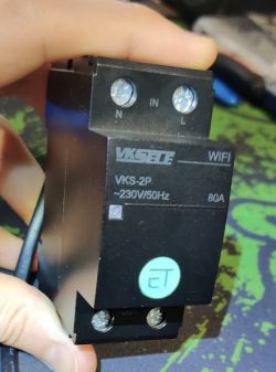
    Exploring VKSELE (EARU?) BK7231T 2P DIN-rail Relay/Energy Meter: Teardown and Comparison

    I bought an item branded VKSELE, but it seems to be out of stock. I also saw what appears to be identical product with EARU brand here and several other sellers selling same things.
    There's another one branded TOMZN, but it doesn't mention the energy meter in the ads, and I can't be sure it's identical.

    I bought the 2P version, which advertises that it includes an energy meter, not just a relay.

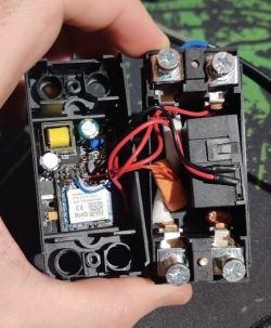
    It's very easy to access; only 2 screws in the back, 2 small clips visible on the outside of the package in line with the screws at either end, and it just opens right up.
    Exploring VKSELE (EARU?) BK7231T 2P DIN-rail Relay/Energy Meter: Teardown and Comparison

    Inside, the mainboard is secured in place with with 2 more small screws, and then the WB3S (BK7231T) is easily accessible.
    There's a big relay, and a CT for energy measurements, but there are no Tuya chips.

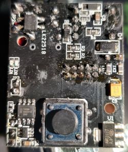
    Other side of the board with the button:
    Exploring VKSELE (EARU?) BK7231T 2P DIN-rail Relay/Energy Meter: Teardown and Comparison

    The CPU board is positioned on a riser from the main board, and there is a small 8-pin chip deep under there which I can't see with pins leading directly to the CPU. Guessing that it's probably BL0937, and checking the pinouts I saw that CF, CF1, SEL pins head to the CPU, so it must be that.

    I flashed it using SPI method (because I damaged the RS232 pins), and it boot up just fine.
    I managed to configure the button and relay, but I haven't worked out how to configure the energy meter yet.

    This appears to be the pin assignment for the chip:
    P6 - Relay
    P24 - Toggle button
    P14 - LED (on when low), acts as a power light; dim while powering on/booting up, setting P14 low will make it very bright, high will turn it off. I can't work out how to control the brightness... maybe it's a DAC pin?
    P8 - BL0937 CF1
    P9 - BL0937 CF
    P26 - BL0937 SEL

    So configuring P6 for "Rel" and P24 for "Btn", I can remotely control the relay, and the push button also works.
    I set P14 to `WifiLED_n`, but I'm not sure if this is how it's intended to be used.

    I *think* I traced the lines correctly for the BL0937, but I get very weird readings like:
    BL0937 Voltage=14.048192, Current=7.541501, Power=0.000000, Total Consumption=0.0 Wh (changes sent 0, skipped 852, saved 1)

    Not sure...
  • ADVERTISEMENT
  • #2 20285771
    p.kaczmarek2
    Moderator Smart Home
    Well, I haven't seen that kind of device before, but with no photos from inside, I can't determine which features it offers.

    Does it even have an energy metering chip? Can you please post more photos so I can help you with configuration?

    Which tool did you use for SPI? My new simple script or the old Tuya one?

    "WifiLed_N" just indicates that WiFi state is AP or connecting or client, by blinking LED at certain speeds...
    Helpful post? Buy me a coffee.
  • #3 20285883
    TurkeyMan
    Level 3  
    I used `spiflash` from https://github.com/OpenBekenIOT/hid_download_py.

    Like I said above, I didn't see any noteworthy IC's on the board, but looking at the BL0937 you mentioned elsewhere I can see it's a tiny chip with only 8 pins. There are 2 small chips with 8 pins, I just dismissed them as trivial logic chips, but one of them must be that

    I can see 3 roles:
    BL0937SEL
    BL0937CF
    BL0937CF1

    How are the pins supposed to be arranged? The pin role wiki document doesn't mention BL0937 at all.

    EDIT: I edited the OP to include some more images and written details that I noticed.

    EDIT2:
    I took a guess that the hidden chip was BL0937, and tried combinations of the 3 pin assignments until I got it right.
    Now the energy meter displays some readings, but it's weird data!

    BL0937 Voltage=15.108433, Current=7.577075, Power=0.000000, Total Consumption=0.0 Wh (changes sent 0, skipped 836, saved 0)

    The voltage and current are both not good numbers. I thought maybe I had CF1 and CF backwards, but switching them gave the same readings...?
    Should all 3 BL0937 pin assignments be in the same channel?
    Perhaps this is just raw data and it needs calibration?
  • #4 20286301
    p.kaczmarek2
    Moderator Smart Home
    BL0937 works by counting pulses on pins by using interrupts. It is very simple to get a false reading with that. You'd need to perform more experiments to know if it's really a BL0937, or just a random data being interpreted as pulses.
    Helpful post? Buy me a coffee.
  • #5 20287032
    TurkeyMan
    Level 3  
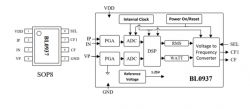
    I checked the datasheet for BL0937 and noted the position of the CF, CF1, SEL pins, it looked like they were connected to the pins leading to the wifi board.
    I was able to poke a meter probe in the gap to contact the pins in the positions they show on the datasheet and I can confirm they are connected to the wifi module, so I'm confident it is BL0937 hidden under the wifi board.
    It seems that it's sort of working... if there's no load, it shows Power=0.000000, when I add a small load it shows a value, when I add a larger load, it shows a value approx double... so it seems that power value is responding to the load, but it's way out of scale... is that possible? I can't make any sense of CF1 (voltage/current). The values are stable... it could just be that they're way out of scale?

    Using interrupts to measure PWM ticks feels potentially problematic; what is the PWM frequency? Does the CPU have enough clock rate?
    How do you read PWM on 2 pins at the same time? Do they both sample at the same time? Can interrupts interrupt eachother?
    Or do they take turns with timeslices? If CF isn't being constantly monitored correctly, it will not accumulate correct totals over long-term?

    Is this what other firmwares on devices that connect BL0937 to IO pins directly are doing? Tasmota/ESPHome also using this strategy? They're quite mature. Do we know what the stock firmware does?
  • ADVERTISEMENT
  • #6 20289734
    p.kaczmarek2
    Moderator Smart Home
    If you know of any other, better way to count ticks, please tell us. As far as I know, the same method is used by Tuya.
    You can see their code here:
    https://github.com/openshwprojects/OpenBK7231.../apps/bk7231t_bl0937_1_plug_demo/src/bl0937.c
    And I think that Tasmota etc are also using that approach.

    I have added automatic change of BL0937 interruprs when pins config changes - but only if driver is already running.

    Have you managed to get that BL0937 working?
    Helpful post? Buy me a coffee.
  • ADVERTISEMENT
  • #7 20293381
    TurkeyMan
    Level 3  
    I haven't managed to get correct readings. Is it possible that the device expects some sort of calibration? Is that a thing for any other devices with similar designs?
  • #8 20293410
    p.kaczmarek2
    Moderator Smart Home
    BL0937 should be calibrated just like in Tasmota. We even have the same commands: "VoltageSet", "PowerSet", "CurrentSet". Just get the 60W bulb, get another meter, and after starting BL0937 with a current pin settings, type those commands with real values to OBK console.

    OBK will now automatically save calibration (in the past, one had to save it by hand in autoexec... but it was changed)
    Helpful post? Buy me a coffee.
  • #9 20293434
    TurkeyMan
    Level 3  
    Oh okay.
    So, do you think calibration is the reason I see those crazy readings I showed above? They're not even remotely close...
    I'll give it a go when I find a light bulb for reference (I only have LED's).
  • #10 20293439
    p.kaczmarek2
    Moderator Smart Home
    TurkeyMan wrote:

    So, do you think calibration is the reason I see those crazy readings I showed above? They're not even remotely close....

    I would be worried that something else is wrong - you might have CF1 and CF swapped or it is not a BL0937 at all, maybe something like an UART device and it's counting random pulses.

    My reasoning for that is because I know that when I was creating BL0937 driver, I have added some default calibration values, which should show "good enough" measurements, I don't know, within a range of 10%-20% error if I were to guess.

    I will not be betting it's BL0937 before I see the BL0937 marking on the chip. Still, I could be wrong, as always...
    Helpful post? Buy me a coffee.
  • ADVERTISEMENT
  • #11 20293450
    TurkeyMan
    Level 3  
    It's impossible to gain visual access to the chip without a de-soldering station. I have high confidence though, because I can look at the datasheet and see the pin positions, and I can easily see 3 lines from the pin positions of CF, CF1, and SEL routed to the wifi module, and I can confirm continuity to those pin positions with a probe on the chip's pins. Unless there's some other chip with exactly 8 pins, and the same pin-out positions, then it's gotta be the right chip.
  • #12 20293484
    p.kaczmarek2
    Moderator Smart Home
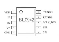
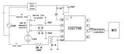
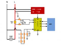
    Well, let's check the other supported energy metering chips...

    Exploring VKSELE (EARU?) BK7231T 2P DIN-rail Relay/Energy Meter: Teardown and Comparison
    Exploring VKSELE (EARU?) BK7231T 2P DIN-rail Relay/Energy Meter: Teardown and Comparison
    Exploring VKSELE (EARU?) BK7231T 2P DIN-rail Relay/Energy Meter: Teardown and Comparison

    It seems that the footprint is very similar in all cases.
    Helpful post? Buy me a coffee.
  • #13 20293497
    TurkeyMan
    Level 3  
    The first chip has 10 pins, so it's not that.
    The last one uses UART via opto-coupler which I didn't see, and only one wire connection. There are 3 connected, which means if it's that last chip, the positions for CF and RI are also connected... should they be connected to BK?
    I think it's most likely that it's BL0937... I can test if pin 5 is GND for further confirmation with a continuity probe.
  • #14 20293514
    p.kaczmarek2
    Moderator Smart Home
    TurkeyMan wrote:

    The last one uses UART via opto-coupler which I didn't see, and only one wire connection.

    That aspect of schematic you can easily ignore. Tuya never uses optocouplers in such situations, after all, those devices does not feature a mains separation of the MCU side.

    Those signals should be connected to BK, but at the moment I don't remember if they connect them directly or (by any chance) through resistors. But we can check...
    Exploring VKSELE (EARU?) BK7231T 2P DIN-rail Relay/Energy Meter: Teardown and Comparison

    Test it and we will see, that's always one more bit of useful information.
    Helpful post? Buy me a coffee.
  • #15 20293659
    TurkeyMan
    Level 3  
    I did notice the signals appears to pass through some resistors.

Topic summary

The discussion revolves around the teardown and analysis of a VKSELE-branded DIN-rail energy meter, which features a BK7231T Wi-Fi module and a relay. Users explore the internal components, particularly the presence of the BL0937 energy metering chip, and share insights on accessing and configuring the device. Initial readings from the energy meter are inconsistent, prompting discussions on potential calibration issues and the need for further testing. The conversation includes technical details about the chip's pin configuration, the method of measuring energy consumption, and comparisons with similar devices from other brands like EARU and TOMZN.
Summary generated by the language model.
ADVERTISEMENT