DIN Rail WiFi switch from aliexpress
![[BK7231N - CBU] TONGOU TO-Q-SY1-JWT Din Rail Wifi Switch with power metering [BK7231N - CBU] TONGOU TO-Q-SY1-JWT Din Rail Wifi Switch with power metering](https://obrazki.elektroda.pl/6026244400_1668642056_thumb.jpg)
Chipset BK7231N module model CBU
![[BK7231N - CBU] TONGOU TO-Q-SY1-JWT Din Rail Wifi Switch with power metering [BK7231N - CBU] TONGOU TO-Q-SY1-JWT Din Rail Wifi Switch with power metering](https://obrazki.elektroda.pl/6842988500_1668642162_thumb.jpg)
EDIT: Power metering uses BL0942 chip.
Pin Assignments:
P9 - RELAY Status LED
P15 - Wifi LED
P17 - Button
P24 - Bridge FORWARD
P26 - Bridge REVERSE
Switch uses Magnetic Polarized Relay:
![[BK7231N - CBU] TONGOU TO-Q-SY1-JWT Din Rail Wifi Switch with power metering [BK7231N - CBU] TONGOU TO-Q-SY1-JWT Din Rail Wifi Switch with power metering](https://obrazki.elektroda.pl/3063966900_1668642616_thumb.jpg)
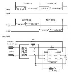
This relay must be driven with bridge driver.
Forward direction closes contact, Reserve direction opens contact.
Relay need to be powered only for changing contact position.
Pulse from length 100-200 ms is requirred to change position.
Then relay holds last position without power.
Relay Driver IC MD7620 (Shanghai-Mingda-Microelectronics)
![[BK7231N - CBU] TONGOU TO-Q-SY1-JWT Din Rail Wifi Switch with power metering [BK7231N - CBU] TONGOU TO-Q-SY1-JWT Din Rail Wifi Switch with power metering](https://obrazki.elektroda.pl/8934422500_1668643025_thumb.jpg)
Operation modes:
![[BK7231N - CBU] TONGOU TO-Q-SY1-JWT Din Rail Wifi Switch with power metering [BK7231N - CBU] TONGOU TO-Q-SY1-JWT Din Rail Wifi Switch with power metering](https://obrazki.elektroda.pl/6160824800_1668643107_thumb.jpg)
Firmware:
https://github.com/openshwprojects/OpenBK7231T_App
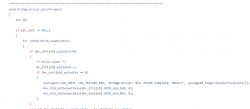
The firmware do not support the bridge driver MD7620 yet, but the work is in progress.
Cool? Ranking DIY


![[BK7231N - CBU] TONGOU TO-Q-SY1-JWT Din Rail Wifi Switch with power metering [BK7231N - CBU] TONGOU TO-Q-SY1-JWT Din Rail Wifi Switch with power metering](https://obrazki.elektroda.pl/2975965200_1676854866_thumb.jpg)
![[BK7231N - CBU] TONGOU TO-Q-SY1-JWT Din Rail Wifi Switch with power metering [BK7231N - CBU] TONGOU TO-Q-SY1-JWT Din Rail Wifi Switch with power metering](https://obrazki.elektroda.pl/2386696800_1676940525_thumb.jpg)
![[BK7231N - CBU] TONGOU TO-Q-SY1-JWT Din Rail Wifi Switch with power metering [BK7231N - CBU] TONGOU TO-Q-SY1-JWT Din Rail Wifi Switch with power metering](https://obrazki.elektroda.pl/1599375500_1676940564_thumb.jpg)
![[BK7231N - CBU] TONGOU TO-Q-SY1-JWT Din Rail Wifi Switch with power metering [BK7231N - CBU] TONGOU TO-Q-SY1-JWT Din Rail Wifi Switch with power metering](https://obrazki.elektroda.pl/4923590600_1678210948_thumb.jpg)
![[BK7231N - CBU] TONGOU TO-Q-SY1-JWT Din Rail Wifi Switch with power metering [BK7231N - CBU] TONGOU TO-Q-SY1-JWT Din Rail Wifi Switch with power metering](https://obrazki.elektroda.pl/2541210100_1678210966_thumb.jpg)
![[BK7231N - CBU] TONGOU TO-Q-SY1-JWT Din Rail Wifi Switch with power metering [BK7231N - CBU] TONGOU TO-Q-SY1-JWT Din Rail Wifi Switch with power metering](https://obrazki.elektroda.pl/1024691400_1678212603_thumb.jpg)
![[BK7231N - CBU] TONGOU TO-Q-SY1-JWT Din Rail Wifi Switch with power metering [BK7231N - CBU] TONGOU TO-Q-SY1-JWT Din Rail Wifi Switch with power metering](https://obrazki.elektroda.pl/1920136300_1678212619_thumb.jpg)
![[BK7231N - CBU] TONGOU TO-Q-SY1-JWT Din Rail Wifi Switch with power metering [BK7231N - CBU] TONGOU TO-Q-SY1-JWT Din Rail Wifi Switch with power metering](https://obrazki.elektroda.pl/9467044900_1678212636_thumb.jpg)
![[BK7231N - CBU] TONGOU TO-Q-SY1-JWT Din Rail Wifi Switch with power metering [BK7231N - CBU] TONGOU TO-Q-SY1-JWT Din Rail Wifi Switch with power metering](https://obrazki.elektroda.pl/1218482100_1678212655_thumb.jpg)
![[BK7231N - CBU] TONGOU TO-Q-SY1-JWT Din Rail Wifi Switch with power metering [BK7231N - CBU] TONGOU TO-Q-SY1-JWT Din Rail Wifi Switch with power metering](https://obrazki.elektroda.pl/2278853600_1678212672_thumb.jpg)
![[BK7231N - CBU] TONGOU TO-Q-SY1-JWT Din Rail Wifi Switch with power metering [BK7231N - CBU] TONGOU TO-Q-SY1-JWT Din Rail Wifi Switch with power metering](https://obrazki.elektroda.pl/6141699900_1678212697_thumb.jpg)
![[BK7231N - CBU] TONGOU TO-Q-SY1-JWT Din Rail Wifi Switch with power metering [BK7231N - CBU] TONGOU TO-Q-SY1-JWT Din Rail Wifi Switch with power metering](https://obrazki.elektroda.pl/7755271100_1678212723_thumb.jpg)
![[BK7231N - CBU] TONGOU TO-Q-SY1-JWT Din Rail Wifi Switch with power metering [BK7231N - CBU] TONGOU TO-Q-SY1-JWT Din Rail Wifi Switch with power metering](https://obrazki.elektroda.pl/3303426400_1678212736_thumb.jpg)
![[BK7231N - CBU] TONGOU TO-Q-SY1-JWT Din Rail Wifi Switch with power metering [BK7231N - CBU] TONGOU TO-Q-SY1-JWT Din Rail Wifi Switch with power metering](https://obrazki.elektroda.pl/9321882600_1678212768_thumb.jpg)
![[BK7231N - CBU] TONGOU TO-Q-SY1-JWT Din Rail Wifi Switch with power metering [BK7231N - CBU] TONGOU TO-Q-SY1-JWT Din Rail Wifi Switch with power metering](https://obrazki.elektroda.pl/1812843300_1678213018_thumb.jpg)
![[BK7231N - CBU] TONGOU TO-Q-SY1-JWT Din Rail Wifi Switch with power metering [BK7231N - CBU] TONGOU TO-Q-SY1-JWT Din Rail Wifi Switch with power metering](https://obrazki.elektroda.pl/1157724600_1678213087_thumb.jpg)
![[BK7231N - CBU] TONGOU TO-Q-SY1-JWT Din Rail Wifi Switch with power metering [BK7231N - CBU] TONGOU TO-Q-SY1-JWT Din Rail Wifi Switch with power metering](https://obrazki.elektroda.pl/5798324300_1678213825_thumb.jpg)
![[BK7231N - CBU] TONGOU TO-Q-SY1-JWT Din Rail Wifi Switch with power metering [BK7231N - CBU] TONGOU TO-Q-SY1-JWT Din Rail Wifi Switch with power metering](https://obrazki.elektroda.pl/3475865100_1678219261_thumb.jpg)
![[BK7231N - CBU] TONGOU TO-Q-SY1-JWT Din Rail Wifi Switch with power metering [BK7231N - CBU] TONGOU TO-Q-SY1-JWT Din Rail Wifi Switch with power metering](https://obrazki.elektroda.pl/1840131800_1678219323_thumb.jpg)
![[BK7231N - CBU] TONGOU TO-Q-SY1-JWT Din Rail Wifi Switch with power metering [BK7231N - CBU] TONGOU TO-Q-SY1-JWT Din Rail Wifi Switch with power metering](https://obrazki.elektroda.pl/3877858800_1678222004_thumb.jpg)
![[BK7231N - CBU] TONGOU TO-Q-SY1-JWT Din Rail Wifi Switch with power metering [BK7231N - CBU] TONGOU TO-Q-SY1-JWT Din Rail Wifi Switch with power metering](https://obrazki.elektroda.pl/2412173500_1678299971_thumb.jpg)
![[BK7231N - CBU] TONGOU TO-Q-SY1-JWT Din Rail Wifi Switch with power metering [BK7231N - CBU] TONGOU TO-Q-SY1-JWT Din Rail Wifi Switch with power metering](https://obrazki.elektroda.pl/2984459100_1678299975_thumb.jpg)
![[BK7231N - CBU] TONGOU TO-Q-SY1-JWT Din Rail Wifi Switch with power metering [BK7231N - CBU] TONGOU TO-Q-SY1-JWT Din Rail Wifi Switch with power metering](https://obrazki.elektroda.pl/3151391400_1678300762_thumb.jpg)
![[BK7231N - CBU] TONGOU TO-Q-SY1-JWT Din Rail Wifi Switch with power metering [BK7231N - CBU] TONGOU TO-Q-SY1-JWT Din Rail Wifi Switch with power metering](https://obrazki.elektroda.pl/4327949700_1693988541_thumb.jpg)


