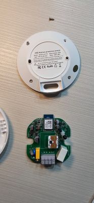
This is a short teardown of Moes mmWave Radar Sensor with CBU module.
Basic information:
Brand: MOES
Model: XZ-HPSW101
Chip: BK7231N [CBU]
Local Vendor: https://expo.tuya.com/product/1053016 (original link wasn't valid anymore so I'm putting this link from tuya)
Teardown Photos:
![[BK7231N] Moes XZ-HPSW101 mmWave Radar Sensor Teardown with CBU Module [BK7231N] Moes XZ-HPSW101 mmWave Radar Sensor Teardown with CBU Module](https://obrazki.elektroda.pl/7286645600_1670470607_thumb.jpg)
![[BK7231N] Moes XZ-HPSW101 mmWave Radar Sensor Teardown with CBU Module [BK7231N] Moes XZ-HPSW101 mmWave Radar Sensor Teardown with CBU Module](https://obrazki.elektroda.pl/1346121500_1670470606_thumb.jpg)
![[BK7231N] Moes XZ-HPSW101 mmWave Radar Sensor Teardown with CBU Module [BK7231N] Moes XZ-HPSW101 mmWave Radar Sensor Teardown with CBU Module](https://obrazki.elektroda.pl/1675454800_1670470606_thumb.jpg)
![[BK7231N] Moes XZ-HPSW101 mmWave Radar Sensor Teardown with CBU Module [BK7231N] Moes XZ-HPSW101 mmWave Radar Sensor Teardown with CBU Module](https://obrazki.elektroda.pl/7407072100_1670470616_thumb.jpg)
![[BK7231N] Moes XZ-HPSW101 mmWave Radar Sensor Teardown with CBU Module [BK7231N] Moes XZ-HPSW101 mmWave Radar Sensor Teardown with CBU Module](https://obrazki.elektroda.pl/5381746700_1670470614_thumb.jpg)
Tuya/smartlife configuration:
![[BK7231N] Moes XZ-HPSW101 mmWave Radar Sensor Teardown with CBU Module [BK7231N] Moes XZ-HPSW101 mmWave Radar Sensor Teardown with CBU Module](https://obrazki.elektroda.pl/2471705000_1670471324_thumb.jpg)
![[BK7231N] Moes XZ-HPSW101 mmWave Radar Sensor Teardown with CBU Module [BK7231N] Moes XZ-HPSW101 mmWave Radar Sensor Teardown with CBU Module](https://obrazki.elektroda.pl/9399189300_1670471331_thumb.jpg)
![[BK7231N] Moes XZ-HPSW101 mmWave Radar Sensor Teardown with CBU Module [BK7231N] Moes XZ-HPSW101 mmWave Radar Sensor Teardown with CBU Module](https://obrazki.elektroda.pl/4307308300_1670471353_thumb.jpg)
![[BK7231N] Moes XZ-HPSW101 mmWave Radar Sensor Teardown with CBU Module [BK7231N] Moes XZ-HPSW101 mmWave Radar Sensor Teardown with CBU Module](https://obrazki.elektroda.pl/6258024500_1670471362_thumb.jpg)
![[BK7231N] Moes XZ-HPSW101 mmWave Radar Sensor Teardown with CBU Module [BK7231N] Moes XZ-HPSW101 mmWave Radar Sensor Teardown with CBU Module](https://obrazki.elektroda.pl/4115735300_1670471375_thumb.jpg)
![[BK7231N] Moes XZ-HPSW101 mmWave Radar Sensor Teardown with CBU Module [BK7231N] Moes XZ-HPSW101 mmWave Radar Sensor Teardown with CBU Module](https://obrazki.elektroda.pl/9194415600_1670471383_thumb.jpg)
![[BK7231N] Moes XZ-HPSW101 mmWave Radar Sensor Teardown with CBU Module [BK7231N] Moes XZ-HPSW101 mmWave Radar Sensor Teardown with CBU Module](https://obrazki.elektroda.pl/1255599100_1670471393_thumb.jpg)
![[BK7231N] Moes XZ-HPSW101 mmWave Radar Sensor Teardown with CBU Module [BK7231N] Moes XZ-HPSW101 mmWave Radar Sensor Teardown with CBU Module](https://obrazki.elektroda.pl/3046431700_1670471402_thumb.jpg)
Flashing Method:
Using serial method with hid_download tool. Start flashing and do a power cycle or ground the CEN pin.
UART TX --> PCB RX
UART RX --> PCB RX
UART GND --> PCB GND
UART 3.3V --> PCB 3.3V
@p.kaczmarek2 I haven't started flashing this yet since I don't really know how to start configuring this.
Could this be using tuya mcu?
Pinout:
TBA


![[BK7231N] Moes XZ-HPSW101 mmWave Radar Sensor Teardown with CBU Module [BK7231N] Moes XZ-HPSW101 mmWave Radar Sensor Teardown with CBU Module](https://obrazki.elektroda.pl/9058194800_1670587935_thumb.jpg)