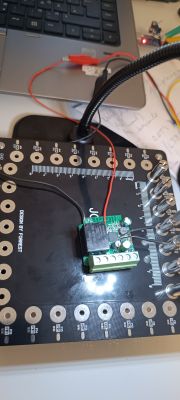
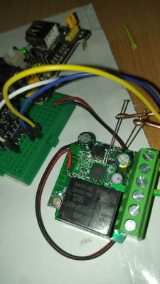
The latest purchase from Aliexpress bring me 2 new type of the Smart Switch.
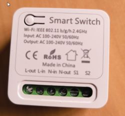
and
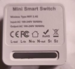
I've ordered 4 pc, and received in the same box two type :
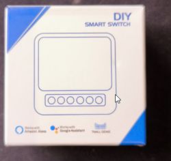
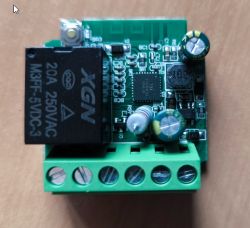
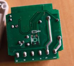
First release have the pushbutton on the back, the second on the front
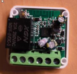
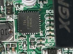
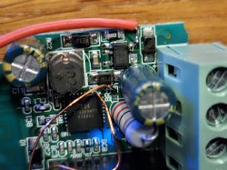
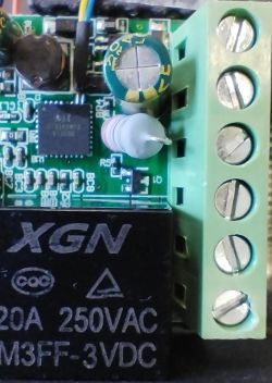
booth are equipped with the same base board, consist the power adapter, relay and T34 chip.
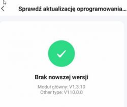
The first try was with the Tuya Cloudcutter, finally i give up when I've found that the software installed there is as below - 1.3.10, on the other post i found information that this is not flashable by the cloud cutter ...
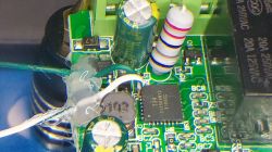
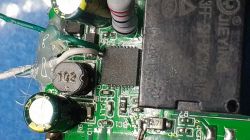
So when i opened the boxt i see that T34 is glued to the main board.
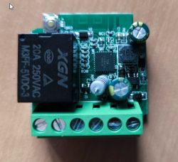
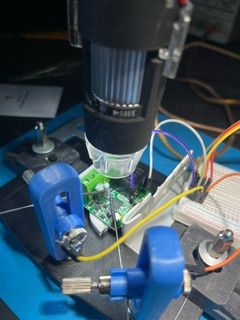
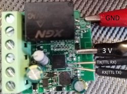
the power taken from UART module i have connected as in the picture:
GND- Violet
3V3 - Violet+RED power
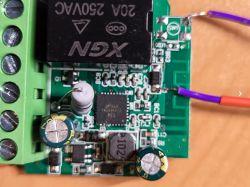
the tricky part is to get access to the programming pins.
the reference say:
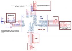
I need access to pins:
T34 25 (RX) <- UART TX
and
T34 26 (TX) <- UART RX
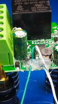
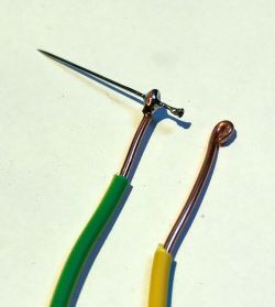
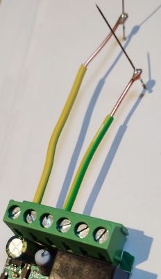
I've mount board in the bracket and preapre two "Needle arms" made with 1,5mm cooper wire and the sewing needle at the end.
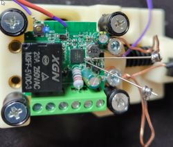
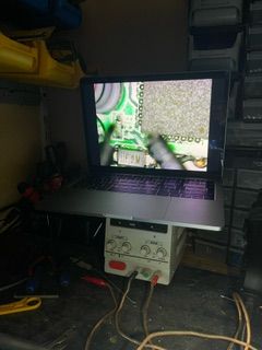
the next 30 min it took me to position the needle on the first board in the right way using magnifing glass to get the proper contact and force in the right direction.
accidently scratching the pins by the sharp end of the needle i took an small piece of the solder between the pins what confused me for an while, so i recommend after placing pins (needles) on - to check with multimeter if they are not shortened just again good magnify glass help.
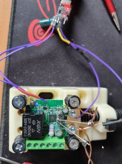
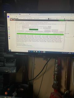
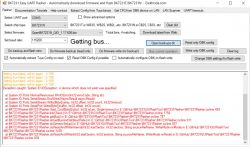
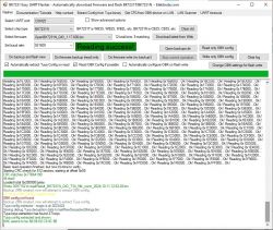
After first succesfull flash of the first one, the other 3 units took only 10 min to be also burn with new becken software via "bk7231flasher_1.1.6"
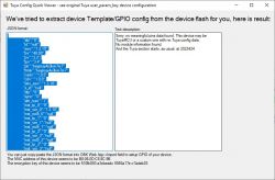
the pin configuration is as follow:
The P14 is the external S1-S2 input of the unit,
while P24 in the internal switch build on the motherboard.
The P16 LED output is negative type, while P15 relay is positive, but it depends to the needs.
The rest is fine
just added startup command "PowerSave 1" to save power ..
Hope it shorten the way for someone ..

and

I've ordered 4 pc, and received in the same box two type :

First release have the pushbutton on the back, the second on the front

booth are equipped with the same base board, consist the power adapter, relay and T34 chip.

The first try was with the Tuya Cloudcutter, finally i give up when I've found that the software installed there is as below - 1.3.10, on the other post i found information that this is not flashable by the cloud cutter ...

So when i opened the boxt i see that T34 is glued to the main board.


the power taken from UART module i have connected as in the picture:
GND- Violet
3V3 - Violet+RED power

the tricky part is to get access to the programming pins.
the reference say:

I need access to pins:
T34 25 (RX) <- UART TX
and
T34 26 (TX) <- UART RX
I've mount board in the bracket and preapre two "Needle arms" made with 1,5mm cooper wire and the sewing needle at the end.

the next 30 min it took me to position the needle on the first board in the right way using magnifing glass to get the proper contact and force in the right direction.
accidently scratching the pins by the sharp end of the needle i took an small piece of the solder between the pins what confused me for an while, so i recommend after placing pins (needles) on - to check with multimeter if they are not shortened just again good magnify glass help.

After first succesfull flash of the first one, the other 3 units took only 10 min to be also burn with new becken software via "bk7231flasher_1.1.6"
the pin configuration is as follow:
Code: JSON
The P14 is the external S1-S2 input of the unit,
while P24 in the internal switch build on the motherboard.
The P16 LED output is negative type, while P15 relay is positive, but it depends to the needs.
The rest is fine
just added startup command "PowerSave 1" to save power ..
Hope it shorten the way for someone ..


