Hi all,
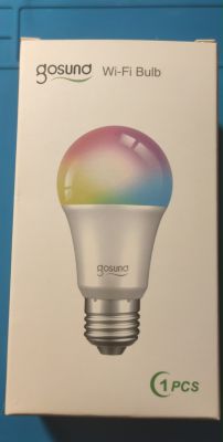
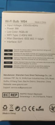
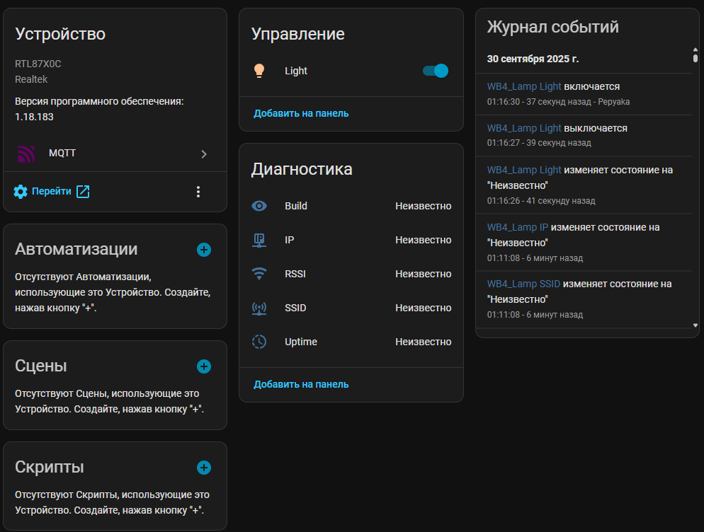
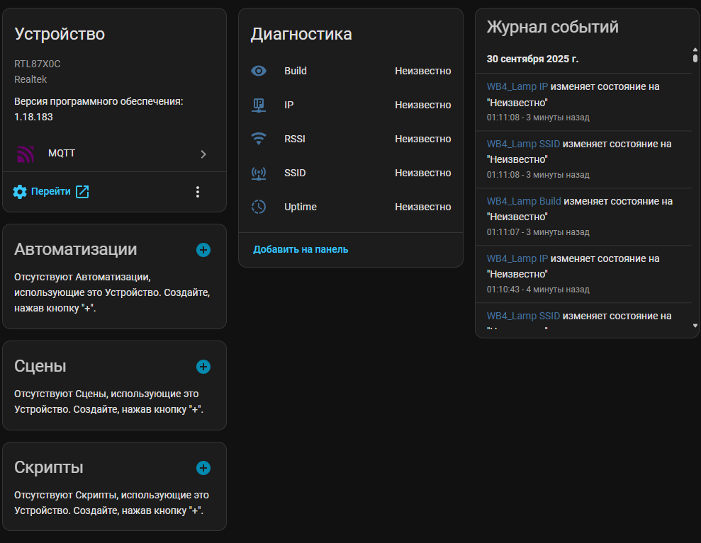
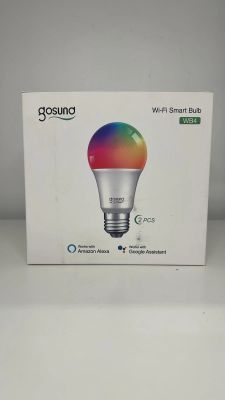
I have a problem with changing the software on the tasmote in the gosund bulb wb4.
Despite soldering in the leads I still have no feedback communication from the controller.
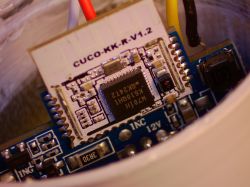
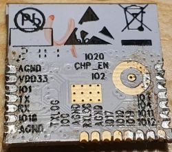
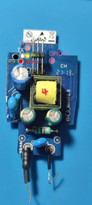
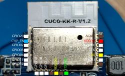
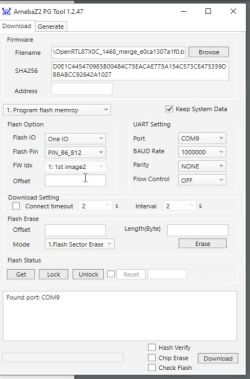
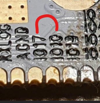
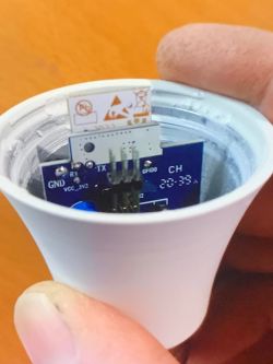
Below I insert pictures I found on a German forum :
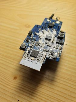
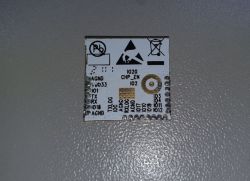
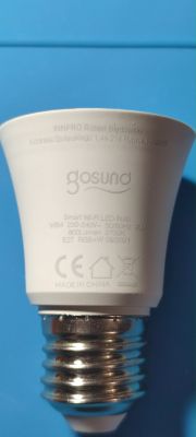
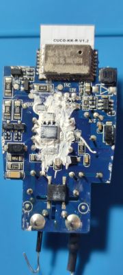
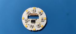
And here my bulb
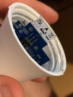
As you can see, mine is newer (?) , does not have the signed pins , although the board looks identical.
Question whether the controller may have been changed and therefore does not detect my computer, or have been routed differently pins ?
Anybody here has changed the software in this bulb ?
I would appreciate an answer .
.
I have a problem with changing the software on the tasmote in the gosund bulb wb4.
Despite soldering in the leads I still have no feedback communication from the controller.
Below I insert pictures I found on a German forum :

And here my bulb

As you can see, mine is newer (?) , does not have the signed pins , although the board looks identical.
Question whether the controller may have been changed and therefore does not detect my computer, or have been routed differently pins ?
Anybody here has changed the software in this bulb ?
I would appreciate an answer


